
 software
 advertising
Similar presentations:


Estun Servo parameter adjustment methods
1.
Estun Servo parameteradjustment methods
Estun overseas department 2009.03
2.
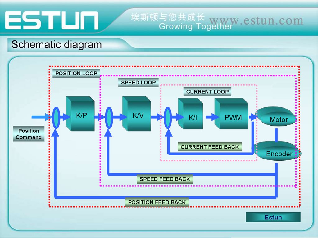
Schematic diagramPOSITION LOOP
SPEED LOOP
CURRENT LOOP
K/P
K/V
K/I
PWM
Motor
Position
Command
CURRENT FEED BACK
Encoder
SPEED FEED BACK
POSITION FEED BACK
Estun
3.
Servo driver parameter adjustment theory foundationServo driver has three feedback loops which are Position loop,
speed loop and current loop. Current loop has the highest
responsiveness. Meanwhile, speed loop must have a higher
responsiveness than position loop.
If we do not abide by this principle, the motor will be caused to
vibration or undesired reaction. While designing the servo drive,
Estun has ensured the highest responsiveness of current loop.
Therefore, users only need to adjust the gain of position and speed
loop.
Generally speaking, the responsiveness of position loop cannot be
faster than speed loop. Hence, it is strongly recommended to
increase the gain of speed loop first, when you want to increase
the gain of position loop. In case you only increase the gain of
position loop, the motor is likely caused to vibrate. This in turn will
cause the increase of speed reference and positioning time rather
than desired decrease.
4.
Servo driver parameter adjustment theory foundationNote: The gain of position loop cannot exceed the
natural frequency of mechanical system. Or, it will
cause to vibration.
In case there is a need of high responsiveness of
the whole system, You must not only ensure the
high responsiveness of servo system (controller,
servo drive, servo motor and encoder) but high
robustness of the mechanical system as well.
This way, the whole system can achieve good
robustness.
5.
Servo drive key parameter adjustment principleSpeed loop gain(Pn102)
Speed loop gain is mainly used to decide the responsiveness of
speed loop. Under the precondition of no vibration of mechanical
system, the bigger the value of this parameter is, the higher the
responsiveness is.
Under the strict precondition that setting value of the load inertia
ratio is within the permission range, speed loop gain can reach
designed value range. It, Consequently, ensures the high
responsiveness of speed loop.
Increase the ratio of speed loop gain can enhance the robustness
of servo system. However, in real application, the ratio of speed
loop gain cannot be too large. Otherwise, it will cause the whole
servo system to vibrate.
6.
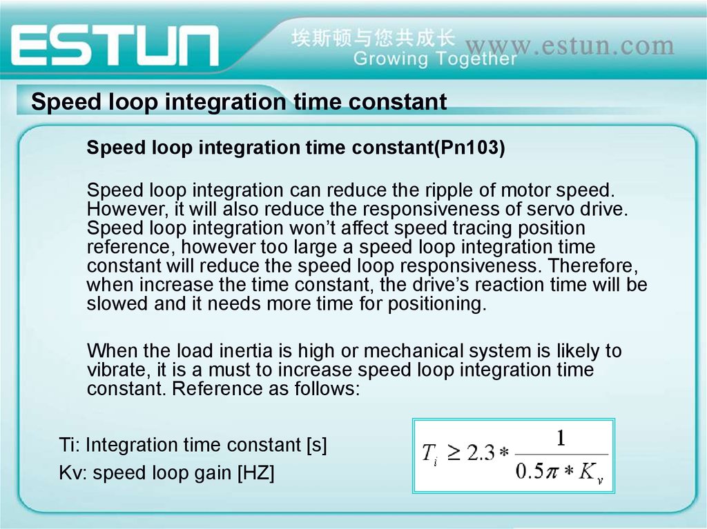
Speed loop integration time constantSpeed loop integration time constant(Pn103)
Speed loop integration can reduce the ripple of motor speed.
However, it will also reduce the responsiveness of servo drive.
Speed loop integration won’t affect speed tracing position
reference, however too large a speed loop integration time
constant will reduce the speed loop responsiveness. Therefore,
when increase the time constant, the drive’s reaction time will be
slowed and it needs more time for positioning.
When the load inertia is high or mechanical system is likely to
vibrate, it is a must to increase speed loop integration time
constant. Reference as follows:
Ti: Integration time constant [s]
Kv: speed loop gain [HZ]
7.
Position loop gainPosition loop gain(Pn104)
Position loop gain is one of the fundamental
index of AC servo system and has close relation to
servo motor & mechanical load. Generally speaking,
higher position loop gain will cause:
1. Higher responsiveness of motor speed
2. Smaller position tracing error
3. Shorter positioning time
However, it requires higher relevant mechanical
system robustness and natural frequency.
8.
Torque reference filter time constantTorque reference filter time constant (Pn105)
The mechanical system may cause sharp noise
due to torque sympathetic vibration in some
occasions. Increase torque reference filter time
constant can reduce or eliminate the vibration
noise.
However, like integration time constant, it will
reduce the responsiveness of the whole system.
Therefore, do not set the value of this parameter
too large.
9.
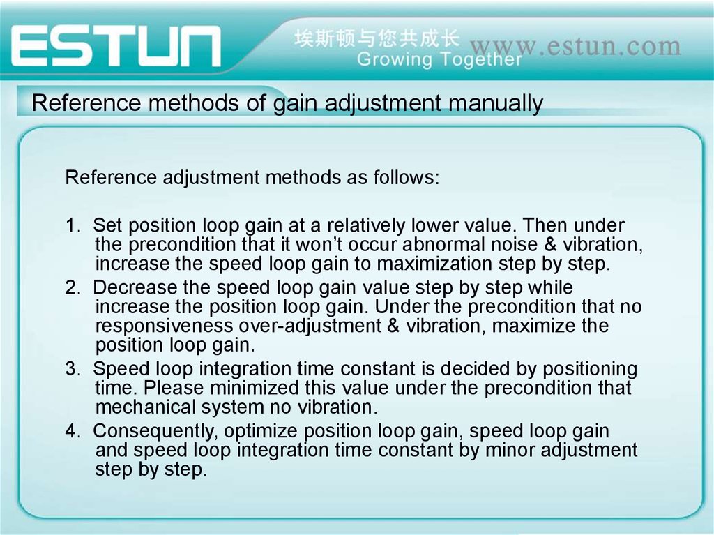
Reference methods of gain adjustment manuallyReference adjustment methods as follows:
1. Set position loop gain at a relatively lower value. Then under
the precondition that it won’t occur abnormal noise & vibration,
increase the speed loop gain to maximization step by step.
2. Decrease the speed loop gain value step by step while
increase the position loop gain. Under the precondition that no
responsiveness over-adjustment & vibration, maximize the
position loop gain.
3. Speed loop integration time constant is decided by positioning
time. Please minimized this value under the precondition that
mechanical system no vibration.
4. Consequently, optimize position loop gain, speed loop gain
and speed loop integration time constant by minor adjustment
step by step.
10.
Estun Automation Technology Co., Ltd.ADD: No.155,Jiangjun Rd., JiangNing District,
Nanjing 211100 P.R. China
Tel: +86-25-52785915 Fax: +86-25-52785576
Email: wangkunlun@estun.com
Website: http://www.estun-servo.com