


 informatics
Similar presentations:
")


")

Selecting Gate Driver Tutorial
1.
Version 1.1Gate Drivers
Presenter: Bipolar Business Unit
Date: November 2018
This presentation contains Diodes proprietary and confidential information
2.
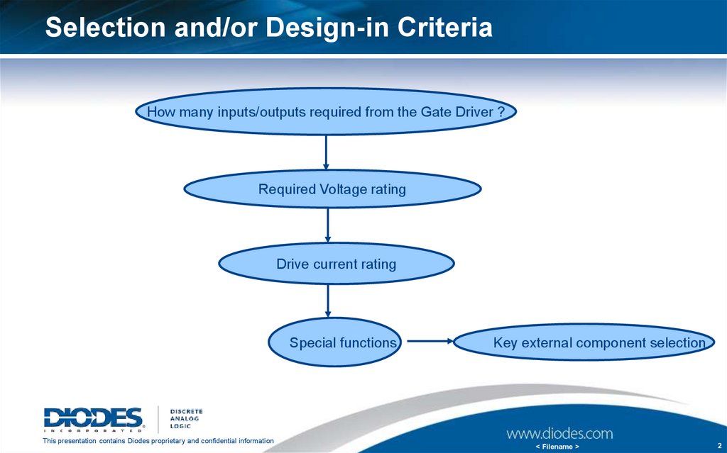
Selection and/or Design-in CriteriaHow many inputs/outputs required from the Gate Driver ?
Required Voltage rating
Drive current rating
Special functions
This presentation contains Diodes proprietary and confidential information
Key external component selection
< Filename >
2
3.
Selection and/or Design-in CriteriaHow many inputs/output are provided for/by the Gate driver?
For the inputs, It depends on the choice of the micro controller and the control
algorithm chosen by the designer
For 2 inputs, the choice is high-side / low-side gate driver
For 1 input, the choice is a half-bridge driver
Number of outputs depend on the number of half bridges that require driving
How to select the voltage rating?
A conservative rule is to pick a voltage rating 3 times the operating voltage, with 1.5
times being a recommended minimum. However, this depends purely on the system
requirements and usually set by the designer
Gate drivers always work with MOSFET/IGBT, best practise is to match the voltage
rating of the chosen MOSFET/IGBT
This presentation contains Diodes proprietary and confidential information
< Filename >
3
4.
Selection and/or design in criteriaHow much drive current is required?
Information about the required gate charge to raise the gate voltage to the desired
level is essential
Gate charge information is provided by the MOSFET manufacturer in their datasheet,
usually for a gate voltage of 10V
Now that we know the required gate charge, we choose the drive current rating
depending on the rise and fall times we are targeting. The equation to use is Qg =
Igate * time
Example: Qg = 50nc. Required Tr = 50ns and Tf = 25ns.
Igate (source) = 50/50 = 1A of source current.
Igate(sink) = 50/25 = 2A of sink current.
The above calculation provides you with a minimum figure. Often it is not easy to
find a tailored gate driver. Best practice is to choose a gate driver with higher than
the required rating and use series gate resistors to limit the source and sink currents
This presentation contains Diodes proprietary and confidential information
< Filename >
4
5.
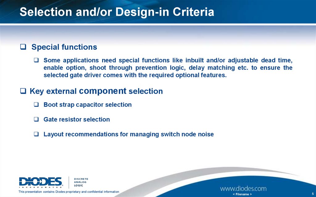
Selection and/or Design-in CriteriaSpecial functions
Some applications need special functions like inbuilt and/or adjustable dead time,
enable option, shoot through prevention logic, delay matching etc. to ensure the
selected gate driver comes with the required optional features.
Key external component selection
Boot strap capacitor selection
Gate resistor selection
Layout recommendations for managing switch node noise
This presentation contains Diodes proprietary and confidential information
< Filename >
5
6.
Bootstrap Capacitor SelectionThe capacitance of the bootstrap capacitor should be high enough to provide the charge required by
the gate of the high-side MOSFET. As a general guideline, it is recommended to make sure the
charge stored by the bootstrap capacitor is about 50 times more than the required gate charge at
operating VCC (usually about 10V to 12V).
The formula to calculate the charge in CBS to provide sufficient gate charge is shown below; Q = C * V
where Q is the gate charge required by the external MOSFET . C is the bootstrap capacitance and V is
the bootstrap voltage VBS
Example: To switch a high-side MOSFET that requires 20nC of gate charge to raise
its gate voltage to 10V, the capacitor size can be calculated as below;
QG(MOSFET) = C(BOOTSTRAP) * V(BOOTSTRAP) * 50
CBS = QG / VBS = 20nC / 10V * 50 = 100nF
This presentation contains Diodes proprietary and confidential information
< Filename >
6
7.
Bootstrap Diode selectionSome of the DGDXXX series gate drivers come with an internal bootstrap diode
Where an external bootstrap diode is necessary, designer should choose its voltage
and current ratings appropriately
VR rating of the bootstrap diode should be >= the voltage rating of the gate driver OR the
MOSFETs, whichever is lower.
Though the average current flowing though the bootstrap diode under normal operation
is very small, it is important to consider the start-up current. When the system is first
powered, there will be an inrush current flowing into the bootstrap diode
Inrush current is directly proportional to the size of the bootstrap capacitance. Larger the
capacitance, larger will be the inrush current. Hence it is important to follow the design
recommendations in the previous slide while choosing the capacitor. Also a series current limiting
resistor is recommended almost every time
Optimum capacitor size and appropriate series resistance combination is important to avoid any
unnecessary stresses on the bootstrap diode
This presentation contains Diodes proprietary and confidential information
< Filename >
7
8.
Gate Resistor SelectionA typical gate drive current control circuit is shown here.
By adjusting the RGon and RGoff resistors respectively, the rise and fall
times can be controlled individually
The effect of the gate resistance on the switching time is shown in the
below example, where the on-time is increased from 68ns to 86ns
This presentation contains Diodes proprietary and confidential information
< Filename >
8
9.
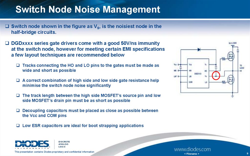
Switch Node Noise ManagementSwitch node shown in the figure as VS, is the noisiest node in the
half-bridge circuits.
DGDxxxx series gate drivers come with a good 50V/ns immunity
at the switch node, however for meeting certain EMI specifications
a few layout techniques are recommended below
Tracks connecting the HO and LO pins to the gates must be made as
wide and short as possible
A correct combination of high side and low side gate resistance help
minimise the switch node noise significantly
The track length between the high side MOSFET’s source pin and low
side MOSFET’s drain pin must be as short as possible
Decoupling capacitors must be placed as close as possible between
the Vcc and COM pins
Low ESR capacitors are ideal for boot strapping applications
This presentation contains Diodes proprietary and confidential information
< Filename >
9
10.
Thank youThis presentation contains Diodes proprietary and confidential information
< Filename >
10