


 informatics
Similar presentations:

")


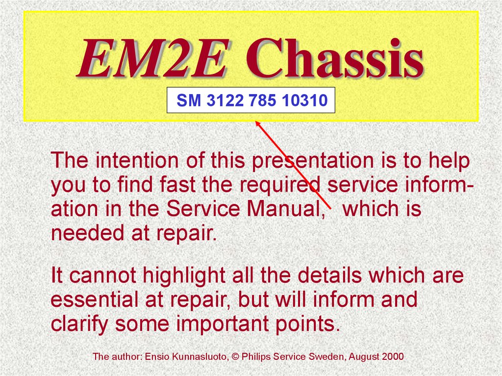
EM2E Chassis
1.
EM2E ChassisSM 3122 785 10310
The intention of this presentation is to help
you to find fast the required service information in the Service Manual, which is
needed at repair.
It cannot highlight all the details which are
essential at repair, but will inform and
clarify some important points.
The author: Ensio Kunnasluoto, © Philips Service Sweden, August 2000
2.
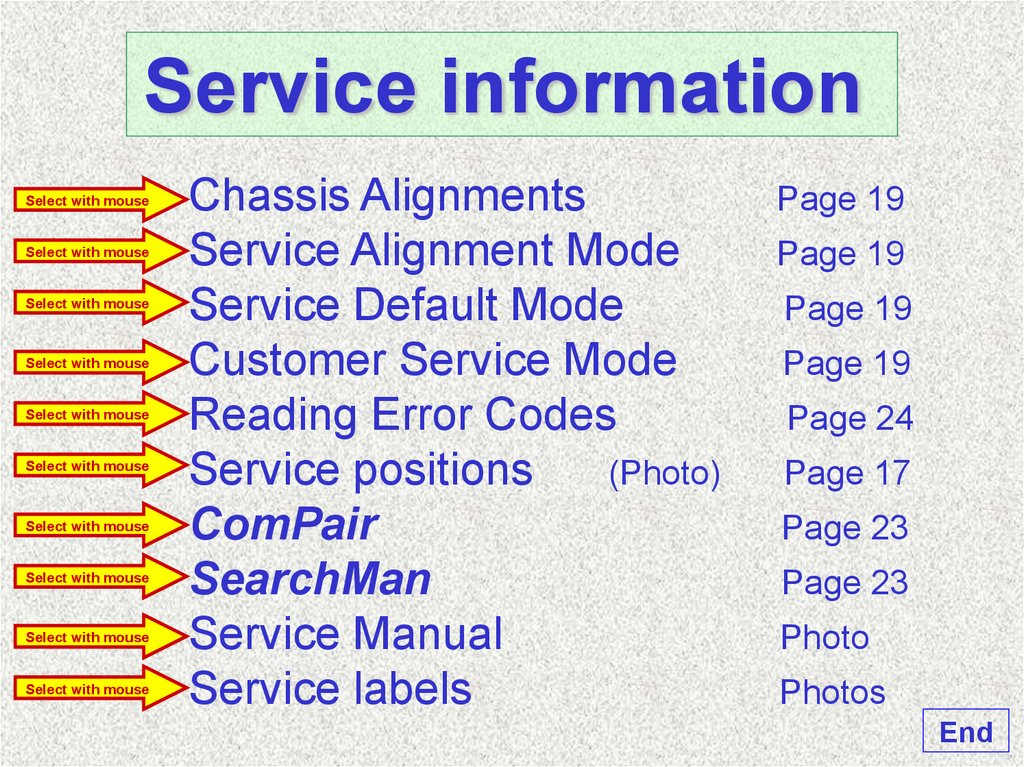
Service informationSelect with mouse
Select with mouse
Select with mouse
Select with mouse
Select with mouse
Select with mouse
Select with mouse
Select with mouse
Select with mouse
Select with mouse
Chassis Alignments
Service Alignment Mode
Service Default Mode
Customer Service Mode
Reading Error Codes
Service positions
(Photo)
ComPair
SearchMan
Service Manual
Service labels
Page 19
Page 19
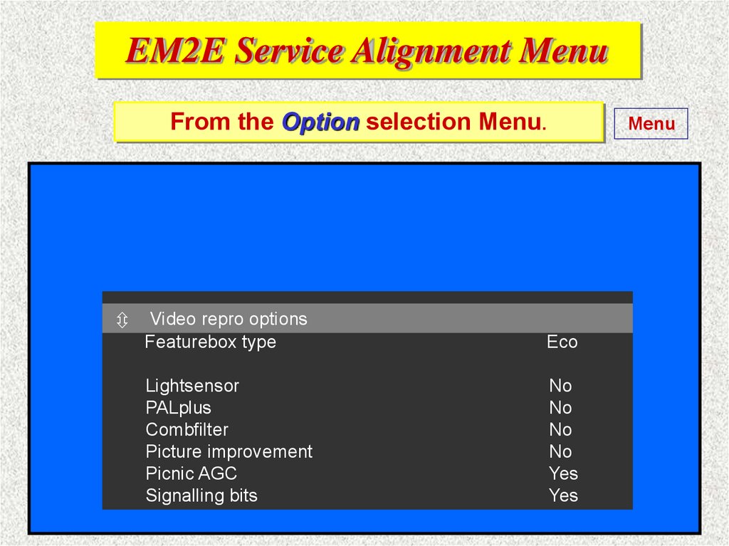
Page 19
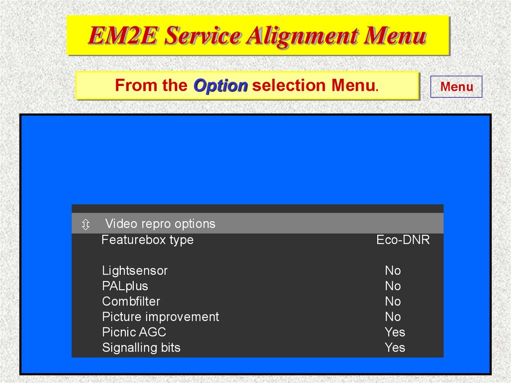
Page 19
Page 24
Page 17
Page 23
Page 23
Photo
Photos
End
3.
The end of presentationThank you for your
kind attention!
4. EM2E Chassis Alignments SM 3122 785 10310
§ 8.1General alignment conditions
page 71
Alignments LSP panel
page 71
8.2.1 Focusing (use crosshatch)
page 71
8.2.2 Vg2 adjustment (use black picture)
page 71
8.2
8.3
Vertical amplitude (use crosshatch) page 71
Adjust picture height with pot. R3603.
8.4
Vertical shift (use crosshatch)
page 71
Adjust with pot. R3609.
Return
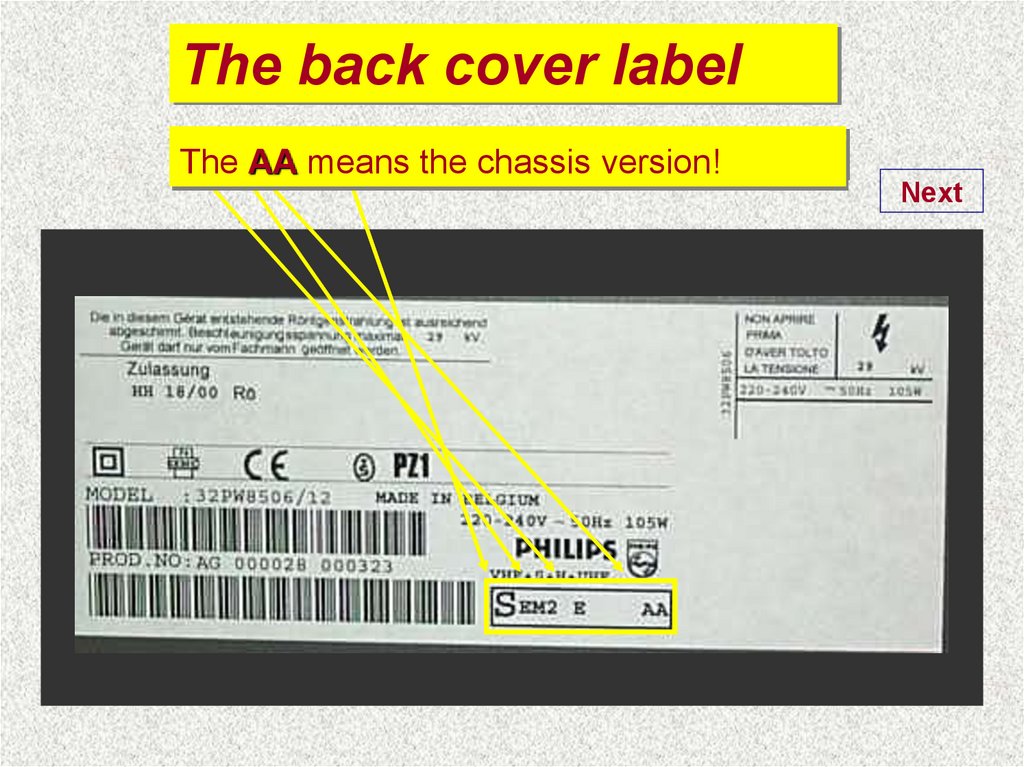
5. EM2E Chassis service modes SM 3122 785 10310
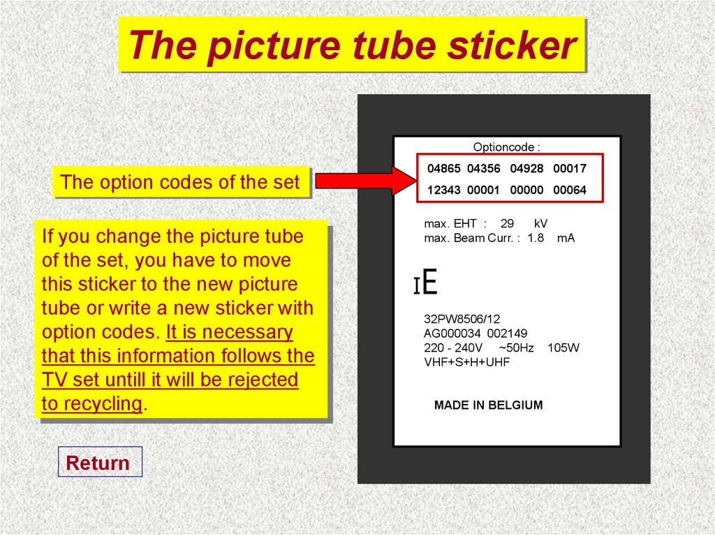
§ 5.2Service Modes
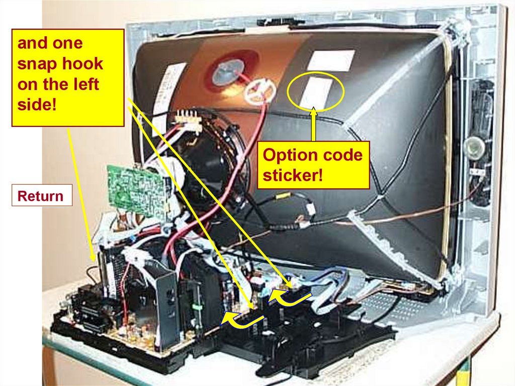
5.2.2 Service Alignment Mode (SAM)Page 19
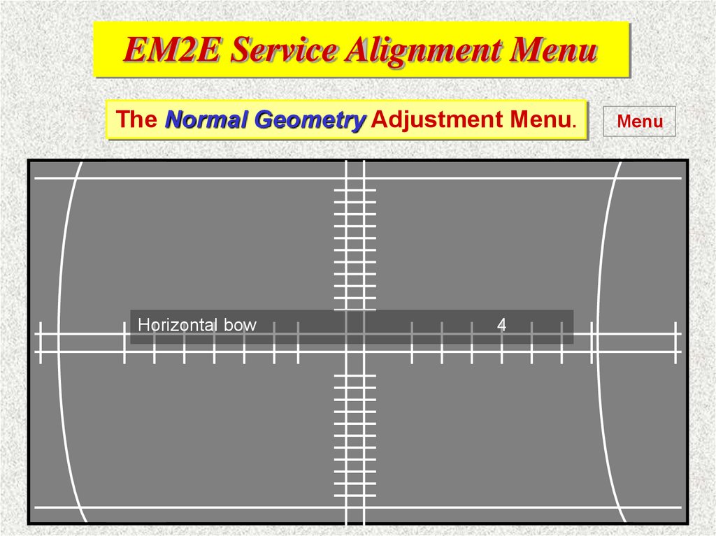
Can be activated by RC by dialling ‘062596’ + ‘OSD’,
by ComPair / DST or short-circuiting item 4005 on SSB.
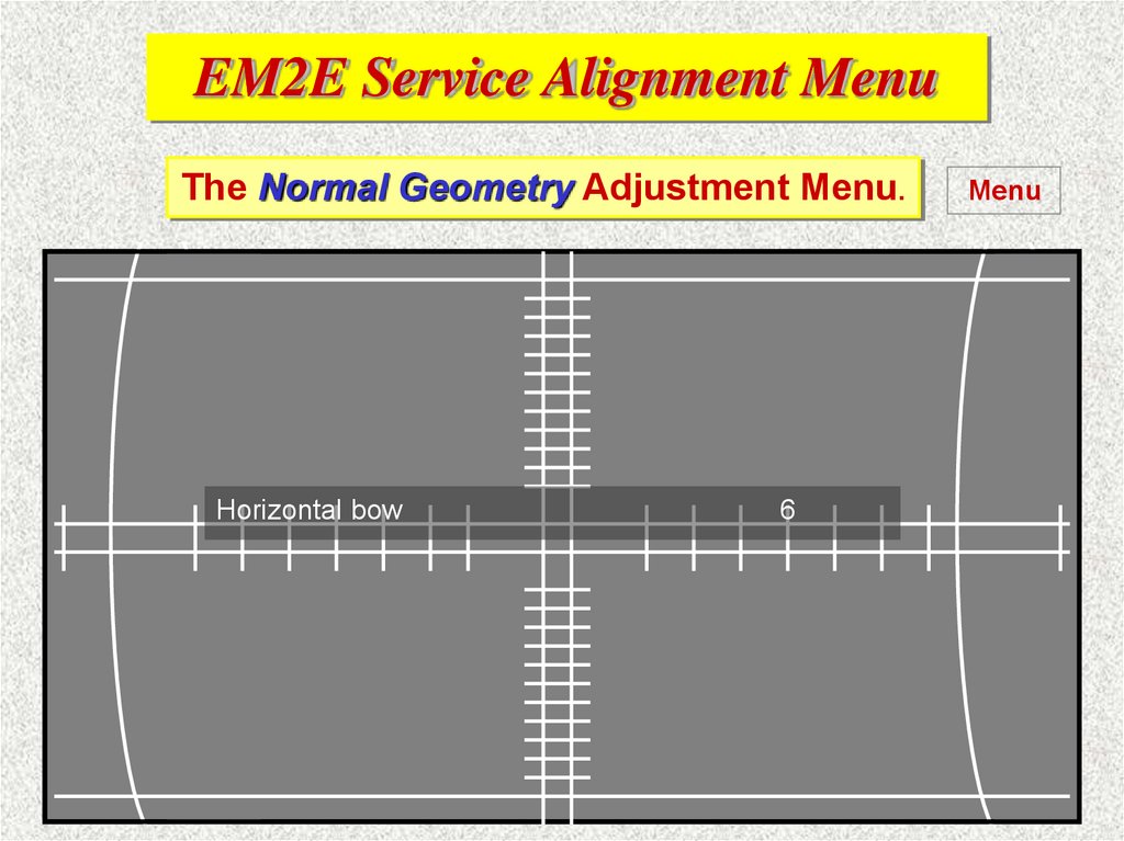
*
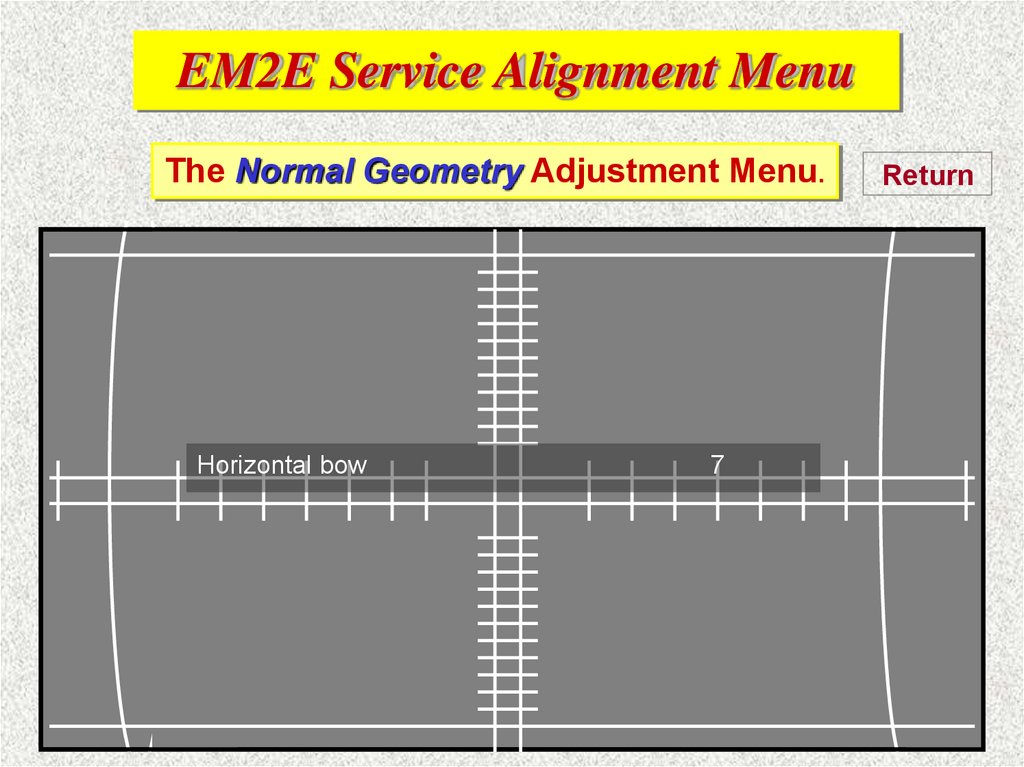
Following slides will show the Service Alignment Mode
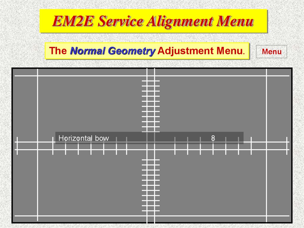
(SAM) menu structure of the EM2E chassis.
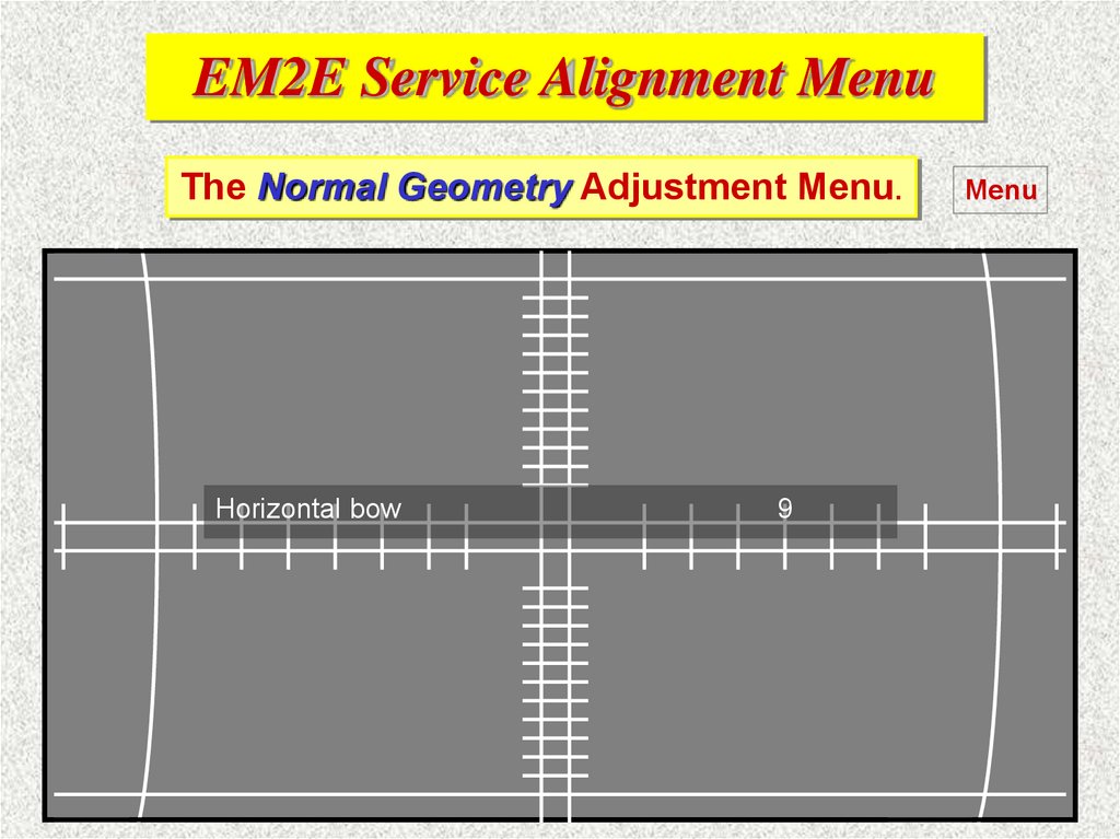
*
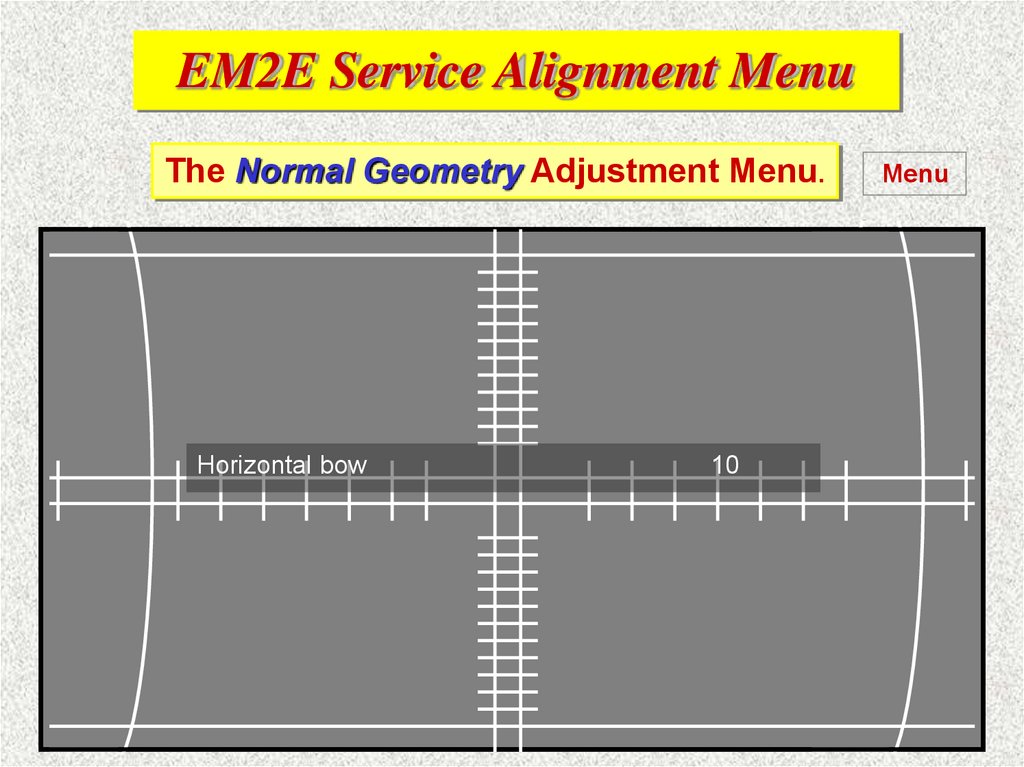
The first slide will show the DST opening menu.
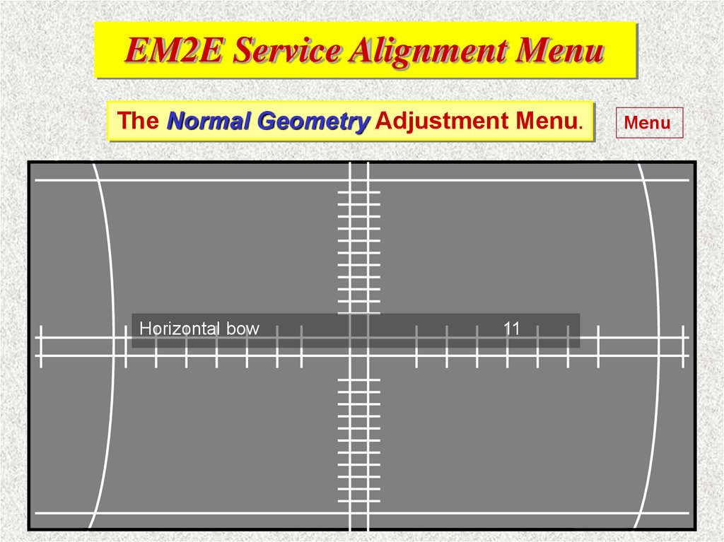
6.
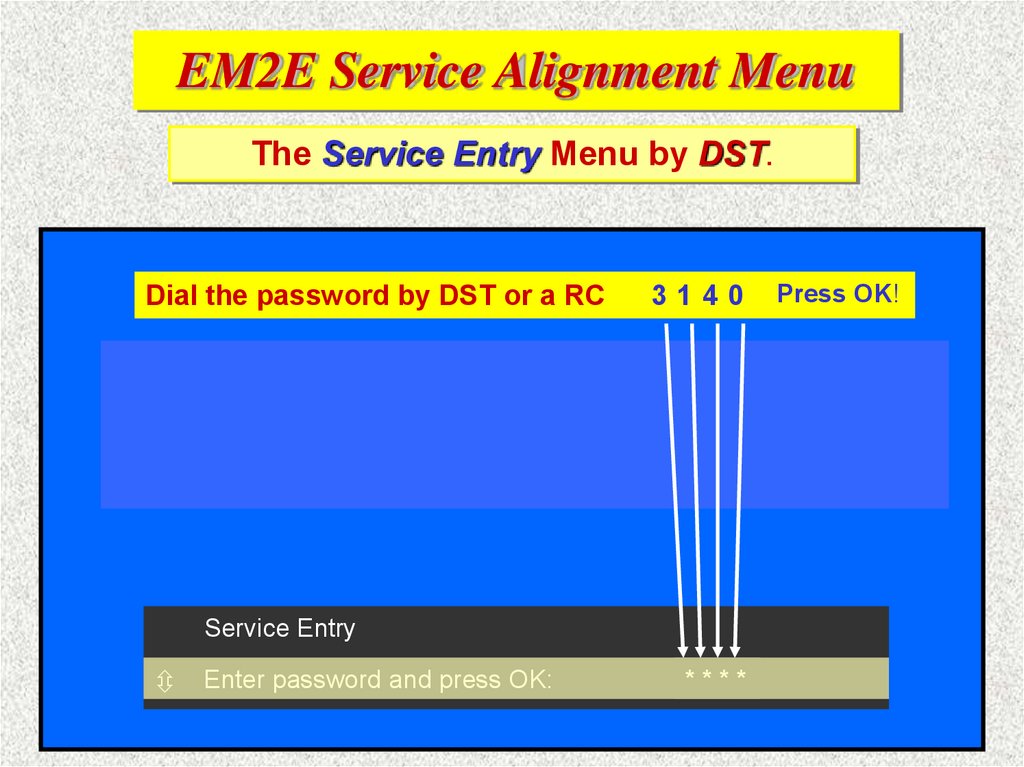
EM2E Service Alignment MenuThe Service Entry Menu by DST.
Dial the password by DST or a RC
3140
Press OK!
Menues shown on 16:9 Widescreen TV
screen
Service Entry
Enter password and press OK:
*- -* -* -*-
7.
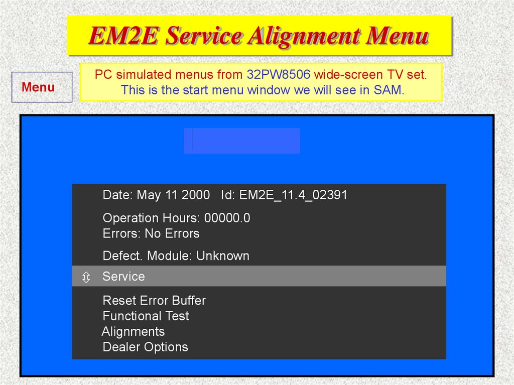
EM2E Service Alignment MenuMenu
PC simulated menus from 32PW8506 wide-screen TV set.
This is the start menu window we will see in SAM.
Testing….
Ready...
Date: May 11 2000 Id: EM2E_11.4_02391
Operation Hours: 00000.0
Errors: No Errors
Defect. Module: Unknown
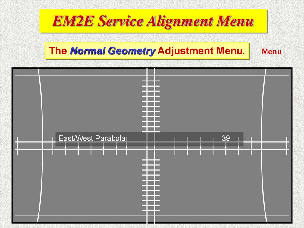
Service
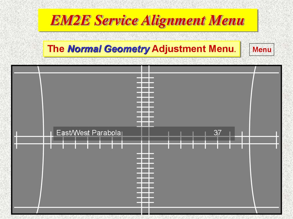
Reset Error Buffer
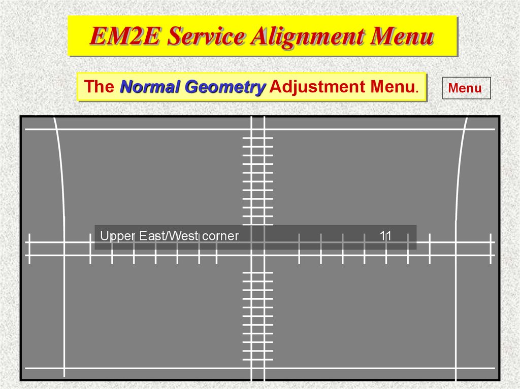
Functional Test
Alignments
Dealer Options
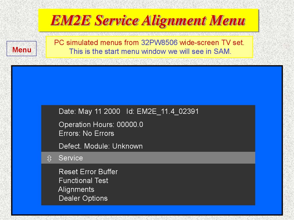
8.
EM2E Service Alignment MenuMenu
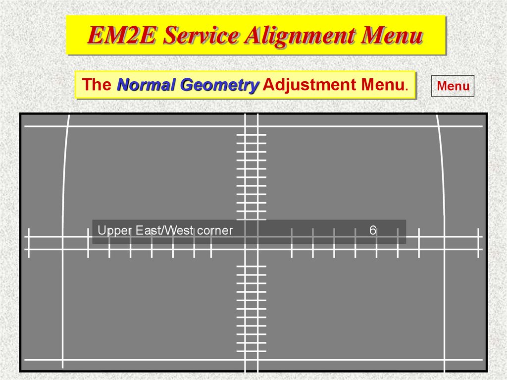
PC simulated menus from 32PW8506 wide-screen TV set.
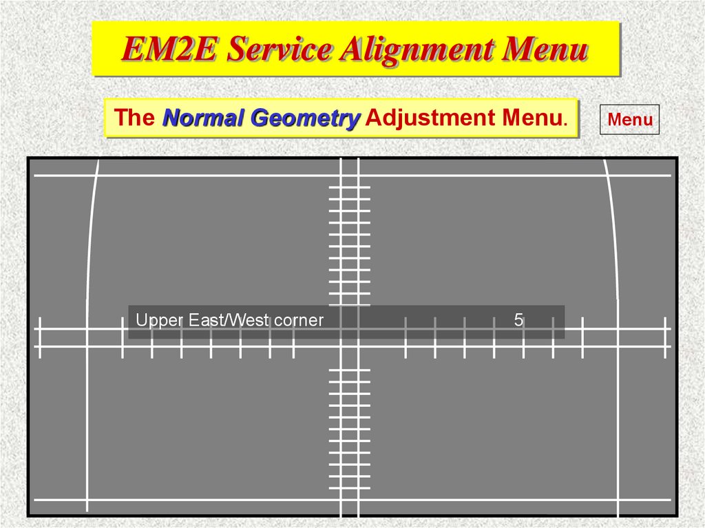
This is the start menu window we will see in SAM.
Date: May 11 2000 Id: EM2E_11.4_02391
Operation Hours: 00000.0
Errors: No Errors
Defect. Module: Unknown
Service
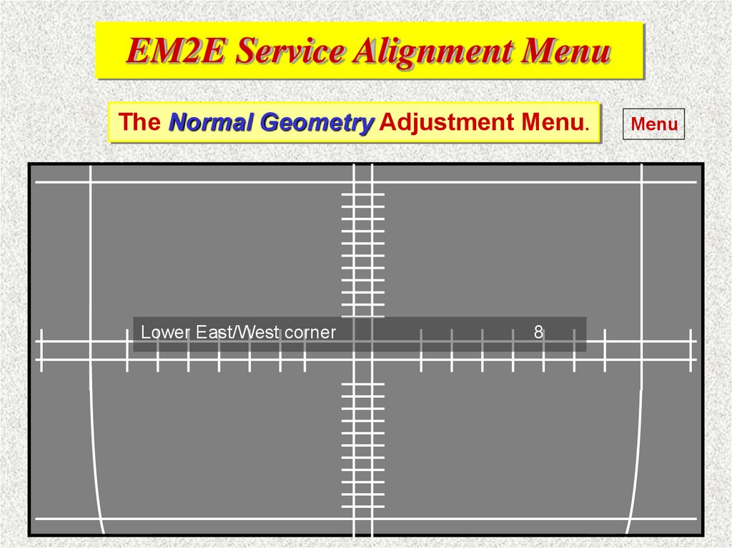
Reset Error Buffer
Functional Test
Alignments
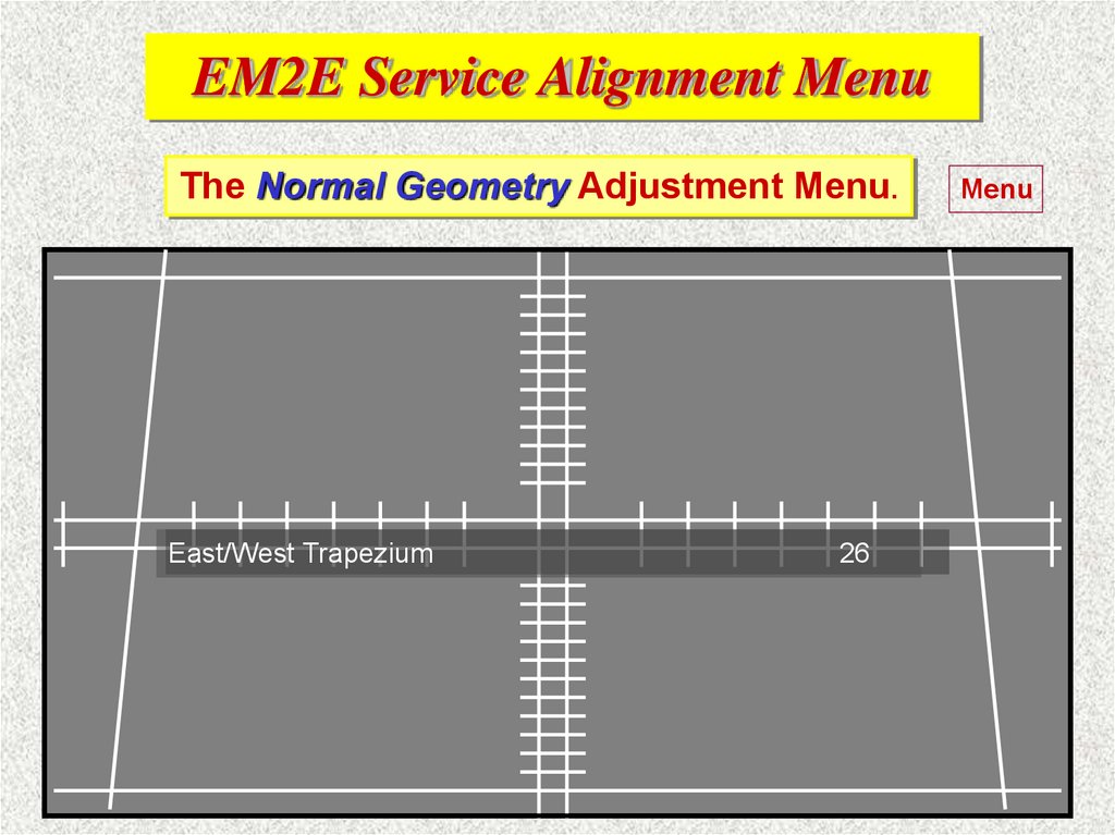
Dealer Options
9.
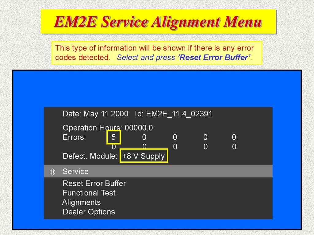
EM2E Service Alignment MenuThis type of information will be shown if there is any error
codes detected. Select and press ’Reset Error Buffer’.
Date: May 11 2000 Id: EM2E_11.4_02391
Operation Hours: 00000.0
Errors:
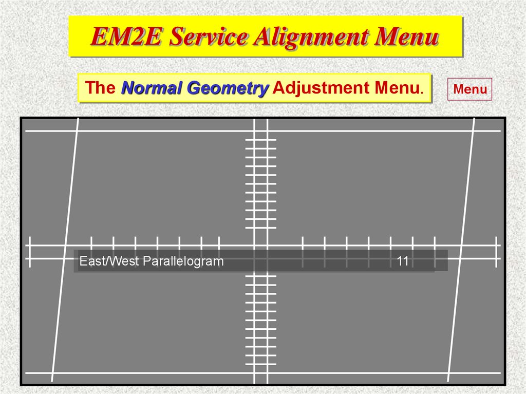
5
0
0
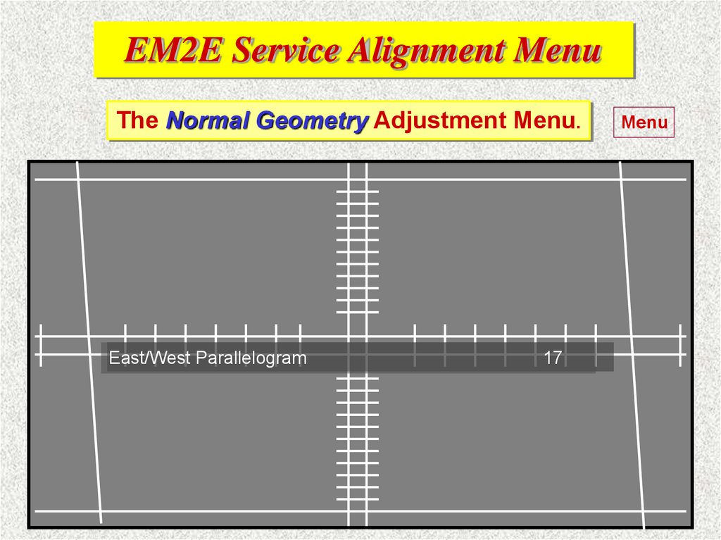
0
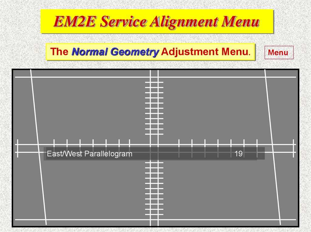
Defect. Module: +8 V Supply
Service
Service
Reset Error Buffer
Functional Test
Alignments
Dealer Options
0
0
0
0
0
0
10.
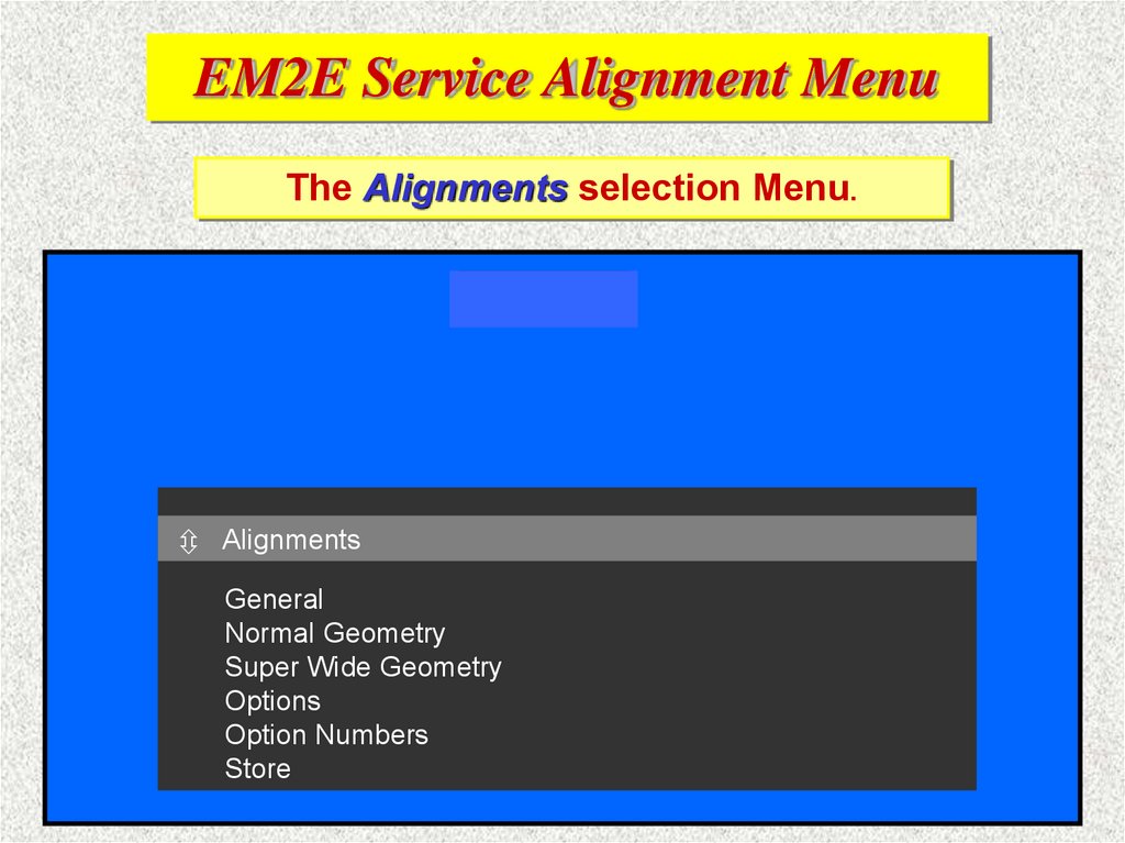
EM2E Service Alignment MenuThe Alignments selection Menu.
Stored
Alignments
Alignments
General
Normal Geometry
Super Wide Geometry
Options
Option Numbers
Store
11.
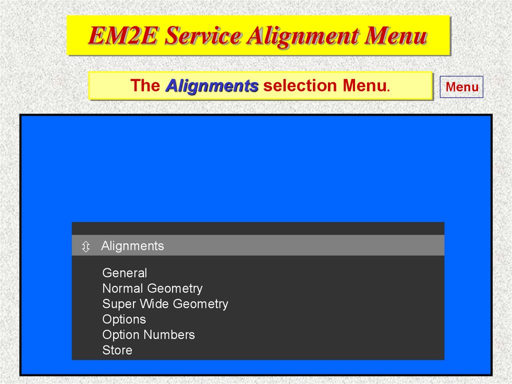
EM2E Service Alignment MenuThe Alignments selection Menu.
Alignments
Alignments
General
Normal Geometry
Super Wide Geometry
Options
Option Numbers
Store
Menu
12.
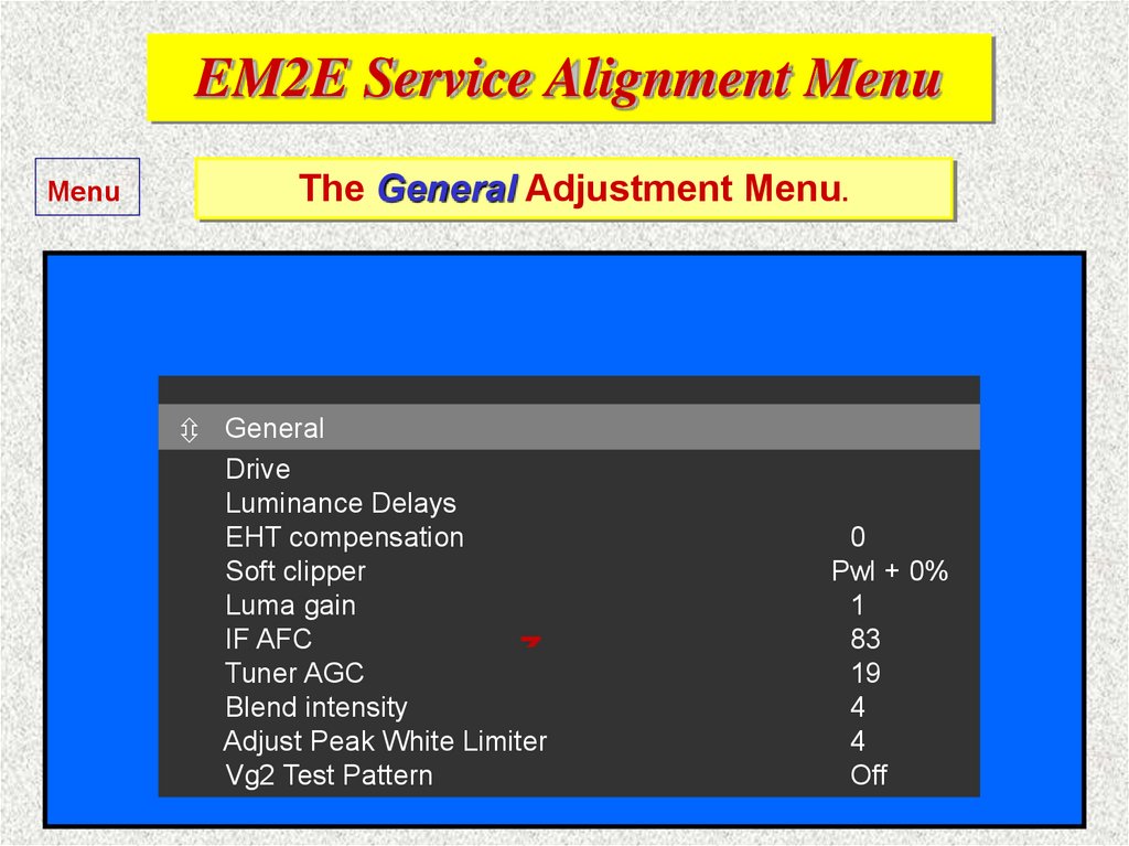
EM2E Service Alignment MenuMenu
The General Adjustment Menu.
General
General
Drive
Luminance Delays
Fixed value
EHT compensation
Soft clipper
Fixed value
Luma gain
Fixed value
IF AFC
Tuner AGC
Blend intensity
Adjust Peak White Limiter
Vg2 Test Pattern
0
Pwl + 0%
1
83
19
4
4
Off
13.
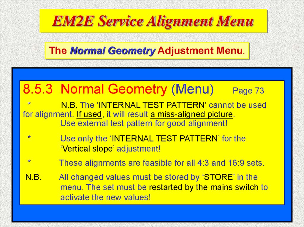
EM2E Service Alignment MenuThe Normal Geometry Adjustment Menu.
8.5.3 Normal Geometry (Menu)
Page 73
*
N.B. The ‘INTERNAL TEST PATTERN’ cannot be used
for alignment. If used, it will result a miss-aligned picture.
Use external test pattern for good alignment!
*
Use only the ‘INTERNAL TEST PATTERN’ for the
‘Vertical slope’ adjustment!
*
These alignments are feasible for all 4:3 and 16:9 sets.
N.B.
All changed values must be stored by ‘STORE’ in the
menu. The set must be restarted by the mains switch to
activate the new values!
14.
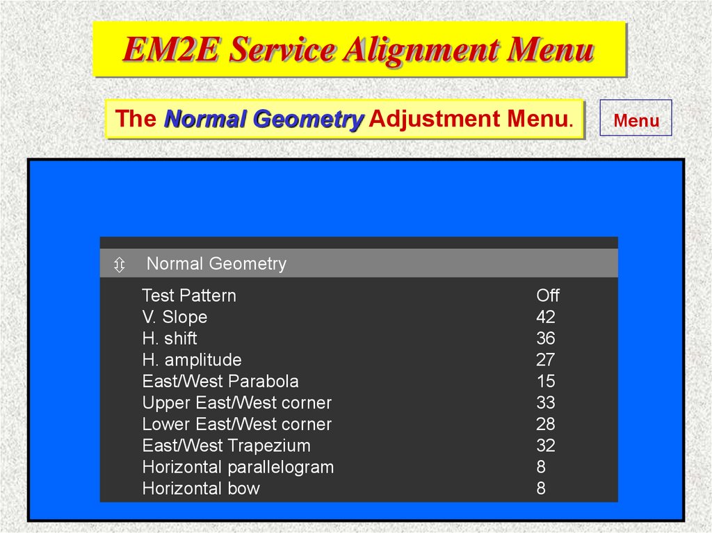
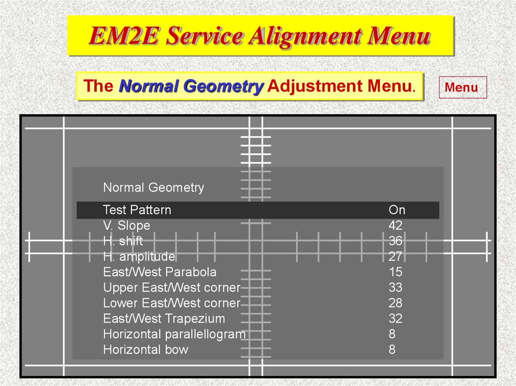
EM2E Service Alignment MenuThe Normal Geometry Adjustment Menu.
Normal
NormalGeometry
Geometry
Test Pattern
V. Slope
H. shift
H. amplitude
East/West Parabola
Upper East/West corner
Lower East/West corner
East/West Trapezium
Horizontal parallelogram
Horizontal bow
Off
42
36
27
15
33
28
32
8
8
Menu
15.
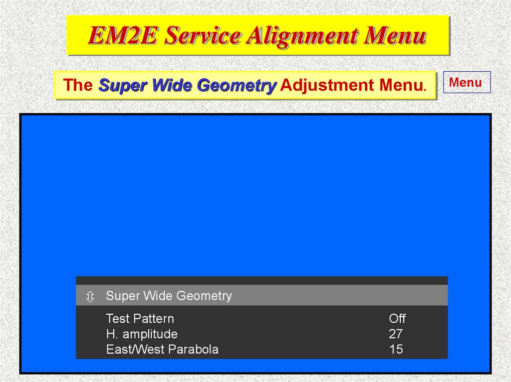
EM2E Service Alignment MenuThe Super Wide Geometry Adjustment Menu.
Menu
8.5.4 Super Wide Geometry (Menu) Page 73
These alignments are valid only for wide screen 16:9 sets.
*
If the ‘Normal Geometry Alignment’ is correctly done.
Adjust:
1.
V. S-Correction: enter and ‘STORE’ the ‘normal geometry
alignment’ value in the case it appears in this menu.
2.
H. Amplitude: enter the ‘normal geometry alignment’ value
subtract
4 from this value and ‘STORE’ it after that.
and
Super
Wide Geometry
3.
E/W
enter and ‘STORE’ the ‘normalOff
geometry
TestParabola:
Pattern
alignment’
value.
H. amplitude
27
East/West Parabola
15
16.
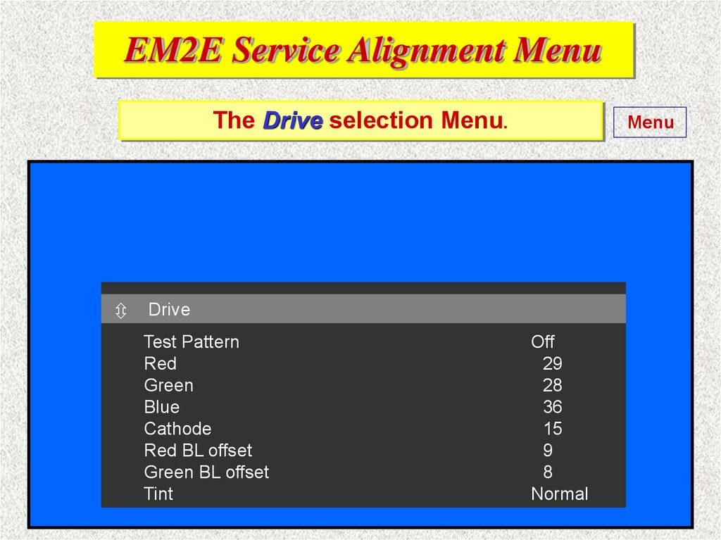
EM2E Service Alignment MenuThe Drive selection Menu.
Menu
Drive
Drive
Test Pattern
Red
Green
Blue
Cathode
Red BL offset
Green BL offset
Tint
Off
29
28
36
15
9
8
Normal
17.
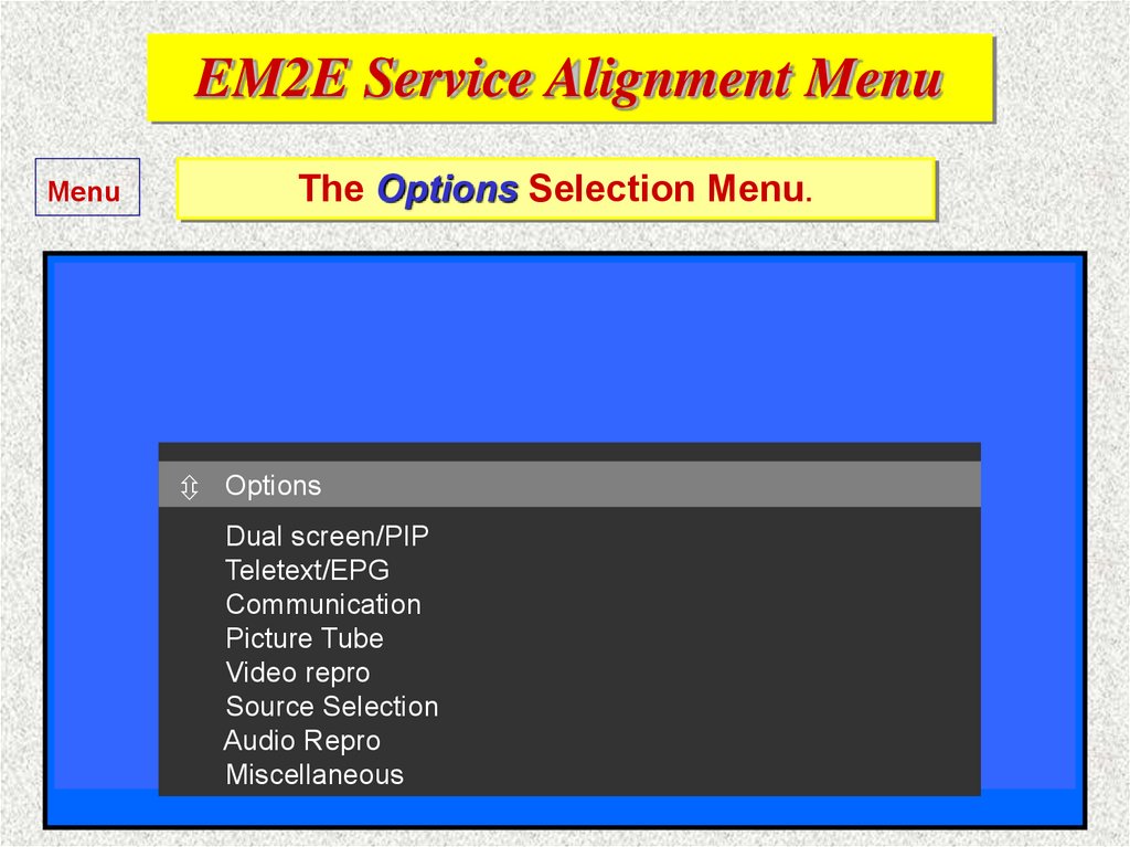
EM2E Service Alignment MenuMenu
The Options Selection Menu.
8.6.2 Options (Menu)
Page 74
This menu is used in case a new hardware / software is
installed in the set. This, to activate the new function or if
it is necessary to deactivate a function at any reason:
All
Options
TV functions have a given option code and can be
changed
by using this menu. Changes made by this menu
Dual screen/PIP
Teletext/EPG
will
automatically change the option numbers, too!
Communication
Picture
Tubeyou can select the correct function and set the
In
this way
Video repro
option
value accordingly to activate / deactivate the TV
Source Selection
function, but Remember to ‘STORE’ the changes!
Audio Repro
Miscellaneous
18.
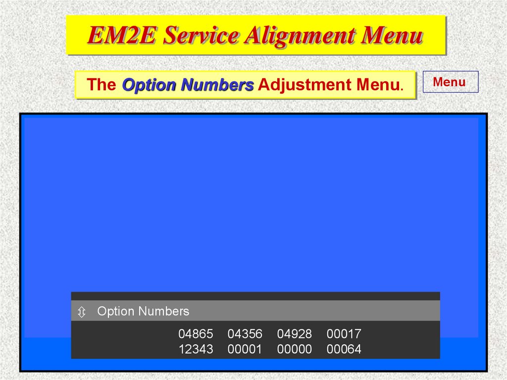
EM2E Service Alignment MenuThe Option Numbers Adjustment Menu.
8.6.4 Option numbers (Menu)
Menu
Page 75
This menu is used if a new (empty NVM) EEPROM is
installed. It is also used if option codes are corrupted of any
reason. ‘Dial’ by RC, ComPair or DST all the digits as
printed on the picture tube sticker by using this menu.
N.B.
Option values must be stored by ‘STORE’ in the menu.
The set must be restarted by the mains switch to activate
the options!
Option
OptionNumbers
Numbers
04865
12343
04356
00001
04928
00000
00017
00064
19.
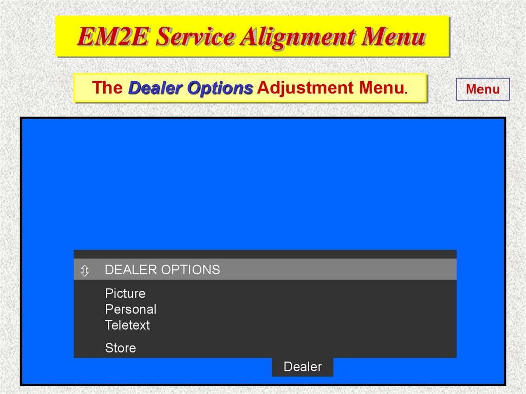
EM2E Service Alignment MenuThe Dealer Options Adjustment Menu.
DEALER OPTIONS
Picture
Personal
Teletext
Store
Dealer
Menu
20.
EM2E Service Alignment MenuThe Dealer Options Adjustment Menu.
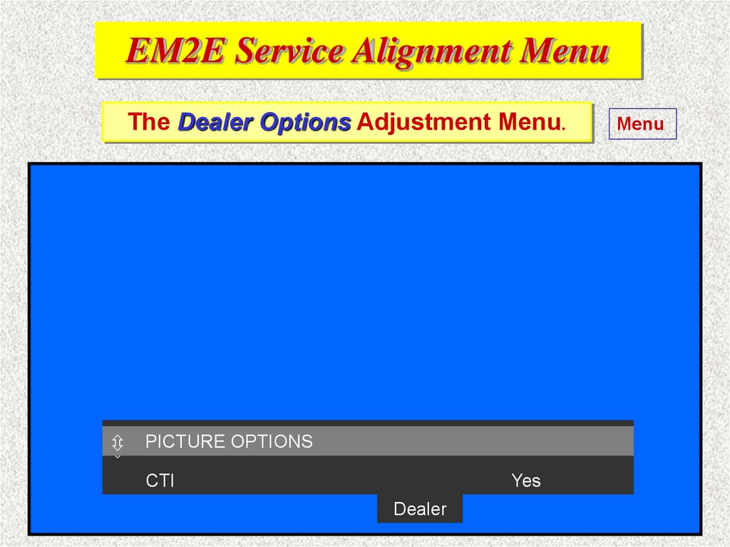
PICTURE
PICTURE OPTIONS
OPTIONS
CTI
Yes
Dealer
Menu
21.
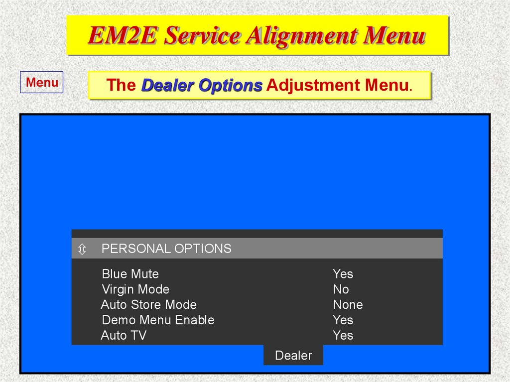
EM2E Service Alignment MenuMenu
The Dealer Options Adjustment Menu.
PERSONAL
PERSONAL OPTIONS
OPTIONS
Blue Mute
Virgin Mode
Auto Store Mode
Demo Menu Enable
Auto TV
Yes
No
PDC-VPS-TXT
Yes
Yes
Dealer
22.
EM2E Service Alignment MenuMenu
The Dealer Options Adjustment Menu.
PERSONAL
PERSONAL OPTIONS
OPTIONS
Blue Mute
Virgin Mode
Auto Store Mode
Demo Menu Enable
Auto TV
Yes
No
None
Yes
Yes
Dealer
23.
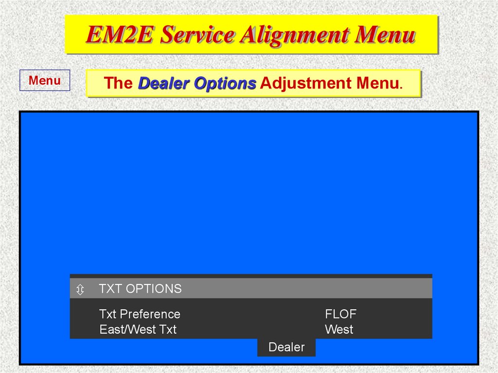
EM2E Service Alignment MenuMenu
The Dealer Options Adjustment Menu.
TXT OPTIONS
Txt Preference
East/West Txt
FLOF
West
Dealer
24.
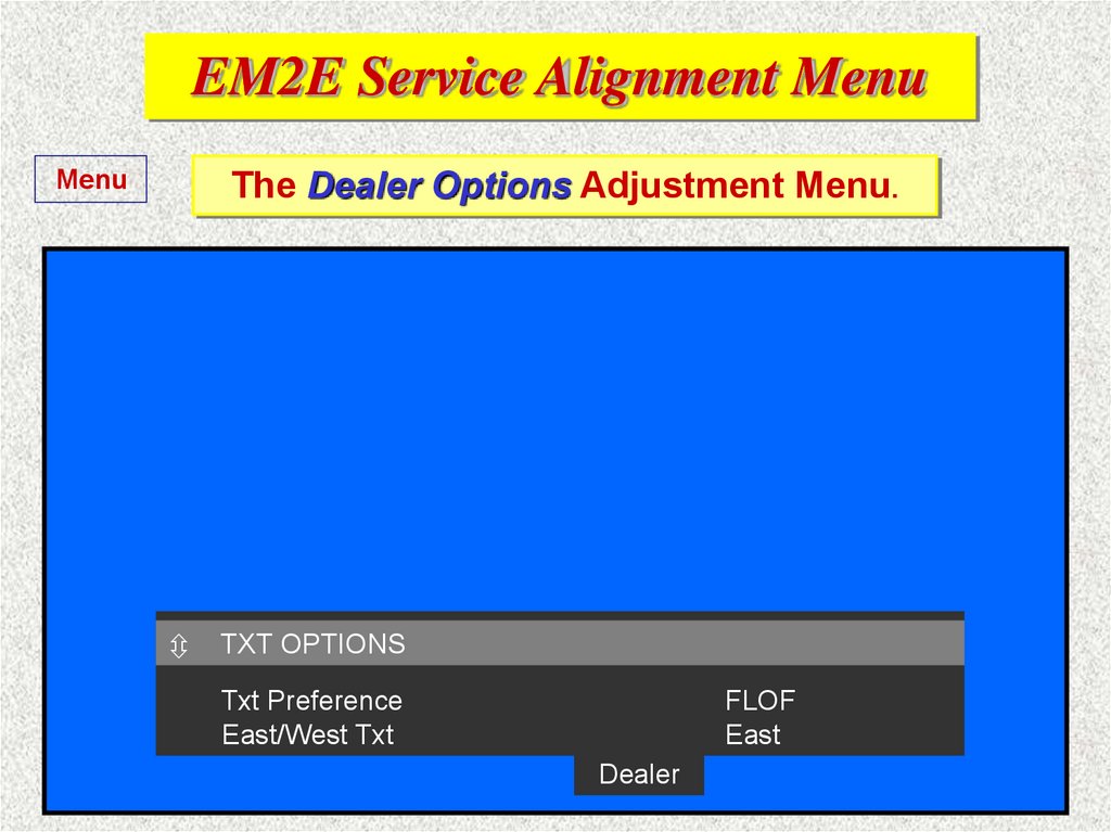
EM2E Service Alignment MenuMenu
The Dealer Options Adjustment Menu.
TXT OPTIONS
Txt Preference
East/West Txt
FLOF
East
Dealer
25.
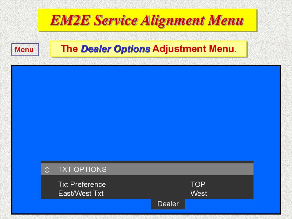
EM2E Service Alignment MenuThe Dealer Options Adjustment Menu.
Menu
TXT OPTIONS
Txt Preference
East/West Txt
TOP
West
Dealer
26.
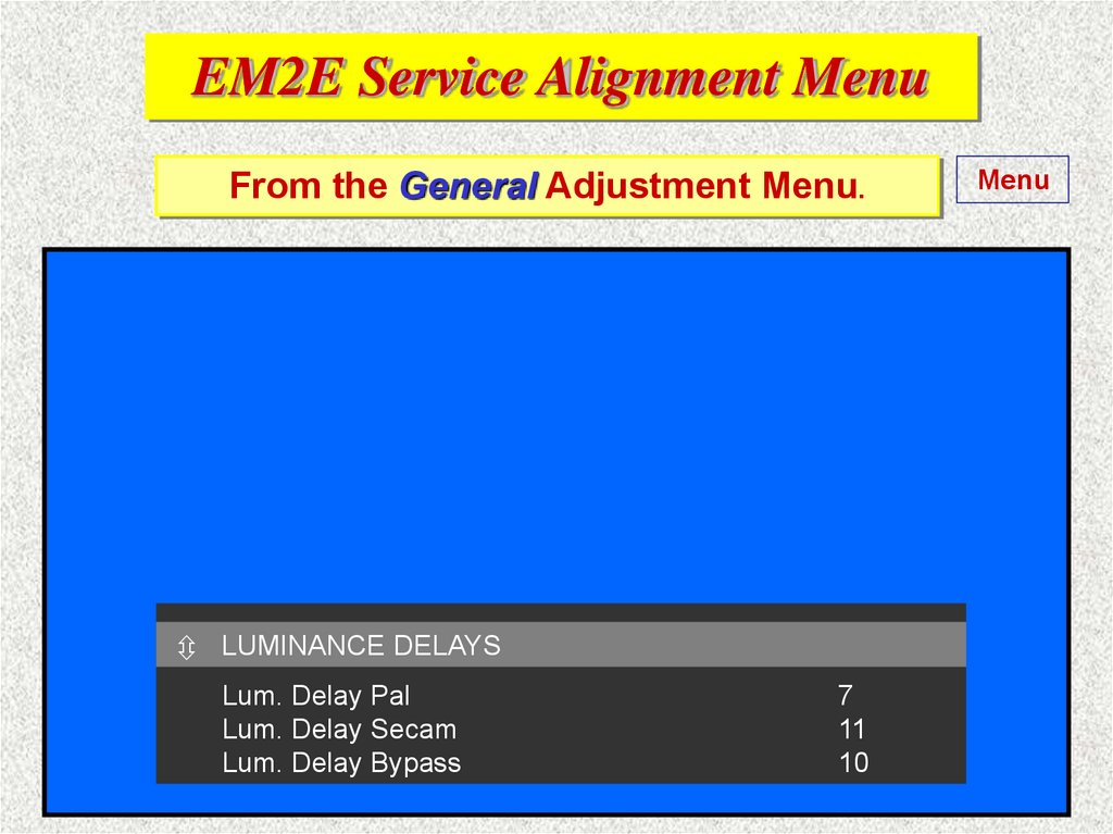
EM2E Service Alignment MenuFrom the General Adjustment Menu.
LUMINANCE
DELAYS
Super Wide Geometry
Lum. Delay Pal
Lum. Delay Secam
Lum. Delay Bypass
7
11
10
Menu
27.
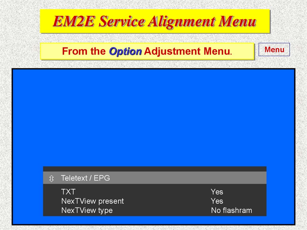
EM2E Service Alignment MenuFrom the Option Adjustment Menu.
Teletext
/ EPG
Super Wide
Geometry
TXT
NexTView present
NexTView type
Yes
Yes
No flashram
Menu
28.
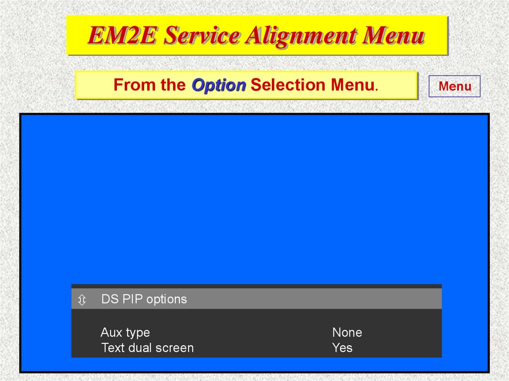
EM2E Service Alignment MenuFrom the Option Selection Menu.
DS PIP options
Aux type
Text dual screen
None
Yes
Menu
29.
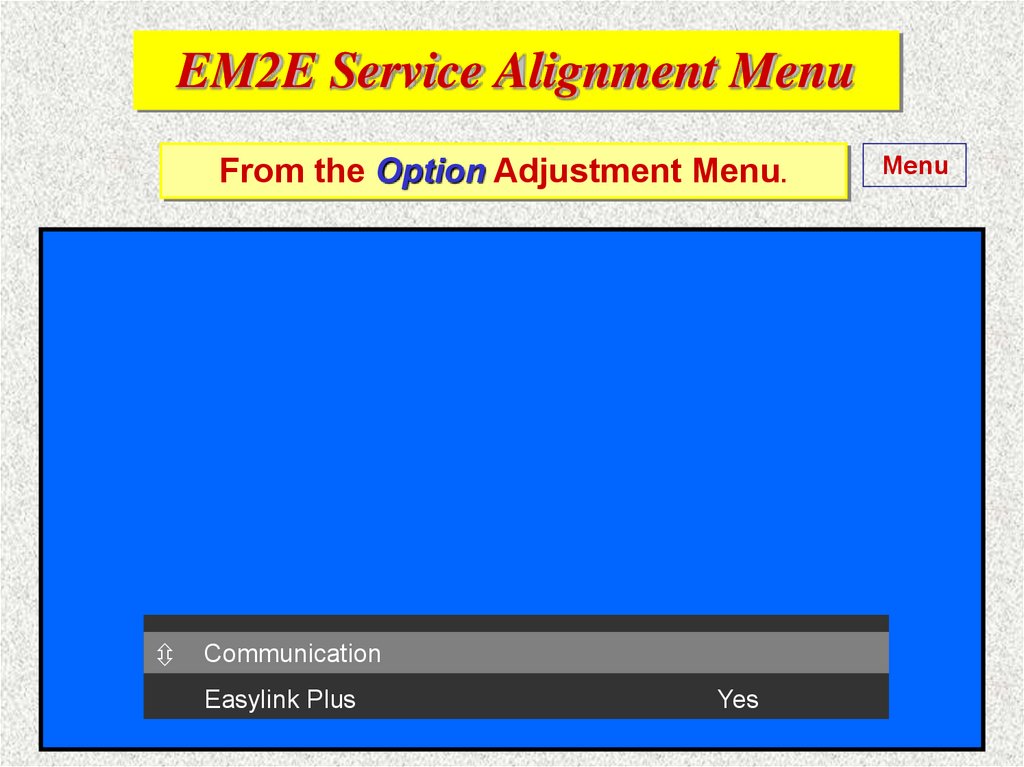
EM2E Service Alignment MenuFrom the Option Adjustment Menu.
Communication
PICTURE OPTIONS
Easylink Plus
Yes
Menu
30.
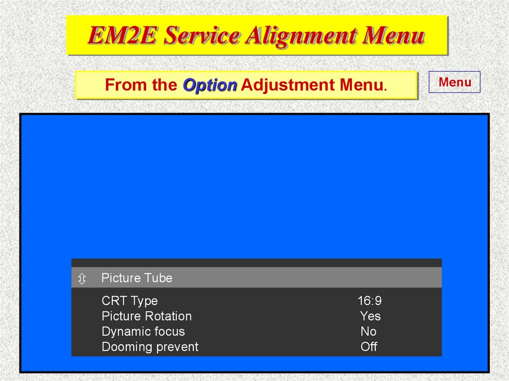
EM2E Service Alignment MenuFrom the Option Adjustment Menu.
Picture
Tube
DEALER
OPTIONS
CRT Type
Picture Rotation
Dynamic focus
Dooming prevent
16:9
Yes
No
Off
Menu
31.
EM2E Service Alignment MenuFrom the Option Adjustment Menu.
Picture
Tube
DEALER
OPTIONS
CRT Type
4:3
Dynamic focus
Dooming prevent
No
Off
Menu
32.
EM2E Service Alignment MenuFrom the Option Adjustment Menu.
Picture
Tube
DEALER
OPTIONS
CRT Type
Picture Rotation
Dynamic focus
Dooming prevent
16:9
Yes
No
SF 16 : 9
Menu
33.
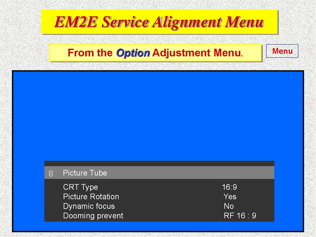
EM2E Service Alignment MenuFrom the Option Adjustment Menu.
Picture
Tube
DEALER
OPTIONS
CRT Type
Picture Rotation
Dynamic focus
Dooming prevent
16:9
Yes
No
RF 16 : 9
Menu
34.
EM2E Service Alignment MenuFrom the Option Adjustment Menu.
Picture
Tube
DEALER
OPTIONS
CRT Type
Picture Rotation
Dynamic focus
Dooming prevent
16:9
Yes
No
4:3
Menu
35.
EM2E Service Alignment MenuMenu
From the Option selection Menu.
Drive
Video repro options
Featurebox type
Lightsensor
PALplus
Combfilter
Picture improvement
Picnic AGC
Signalling bits
Prozonic
No
No
No
No
Yes
Yes
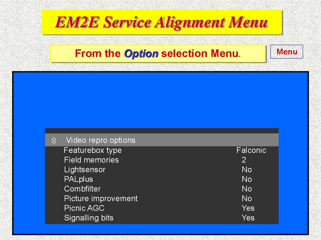
36.
EM2E Service Alignment MenuFrom the Option selection Menu.
Drive
Video repro options
Featurebox type
Field memories
Lightsensor
PALplus
Combfilter
Picture improvement
Picnic AGC
Signalling bits
Falconic
2
No
No
No
No
Yes
Yes
Menu
37.
EM2E Service Alignment MenuFrom the Option selection Menu.
Menu
Drive
Video repro options
Featurebox type
Eco
Lightsensor
PALplus
Combfilter
Picture improvement
Picnic AGC
Signalling bits
No
No
No
No
Yes
Yes
38.
EM2E Service Alignment MenuFrom the Option selection Menu.
Drive
Video repro options
Featurebox type
Lightsensor
PALplus
Combfilter
Picture improvement
Picnic AGC
Signalling bits
Menu
Eco-DNR
No
No
No
No
Yes
Yes
39.
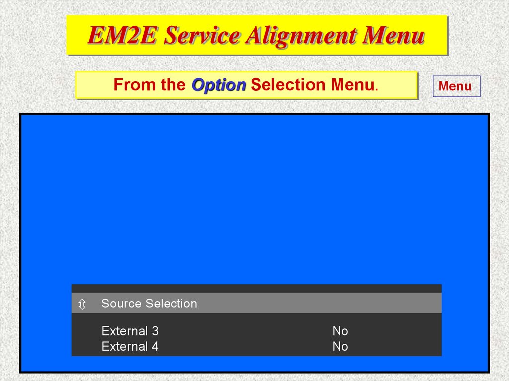
EM2E Service Alignment MenuFrom the Option Selection Menu.
Source Selection
External 3
External 4
No
No
Menu
40.
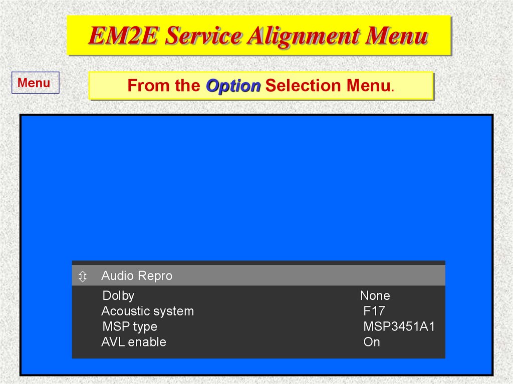
EM2E Service Alignment MenuMenu
From the Option Selection Menu.
Audio Repro
Dolby
Acoustic system
MSP type
AVL enable
None
F17
MSP3451A1
On
41.
EM2E Service Alignment MenuMenu
From the Option Selection Menu.
Audio Repro
Dolby
Rear speakers
Acoustic system
MSP type
AVL enable
Pro Logic
Virtual
F17
MSP3451A1
On
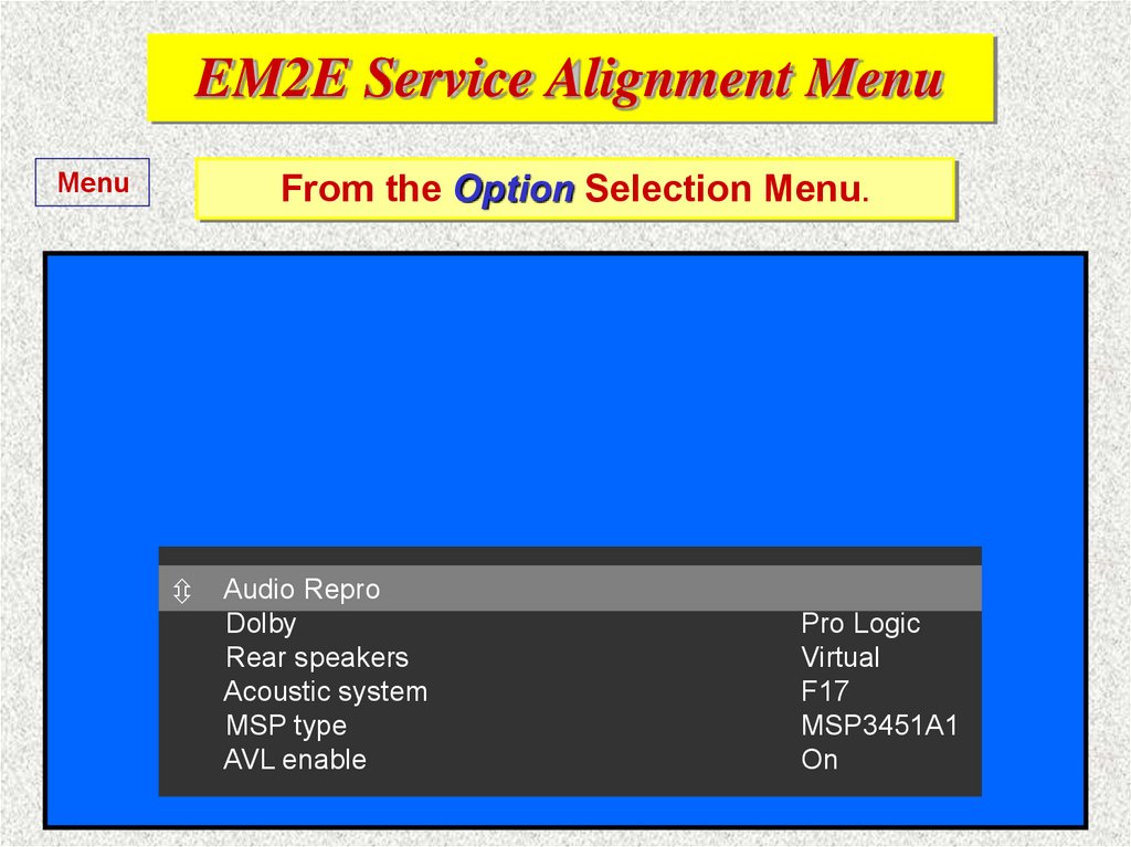
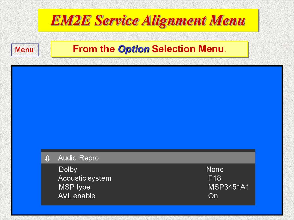
42.
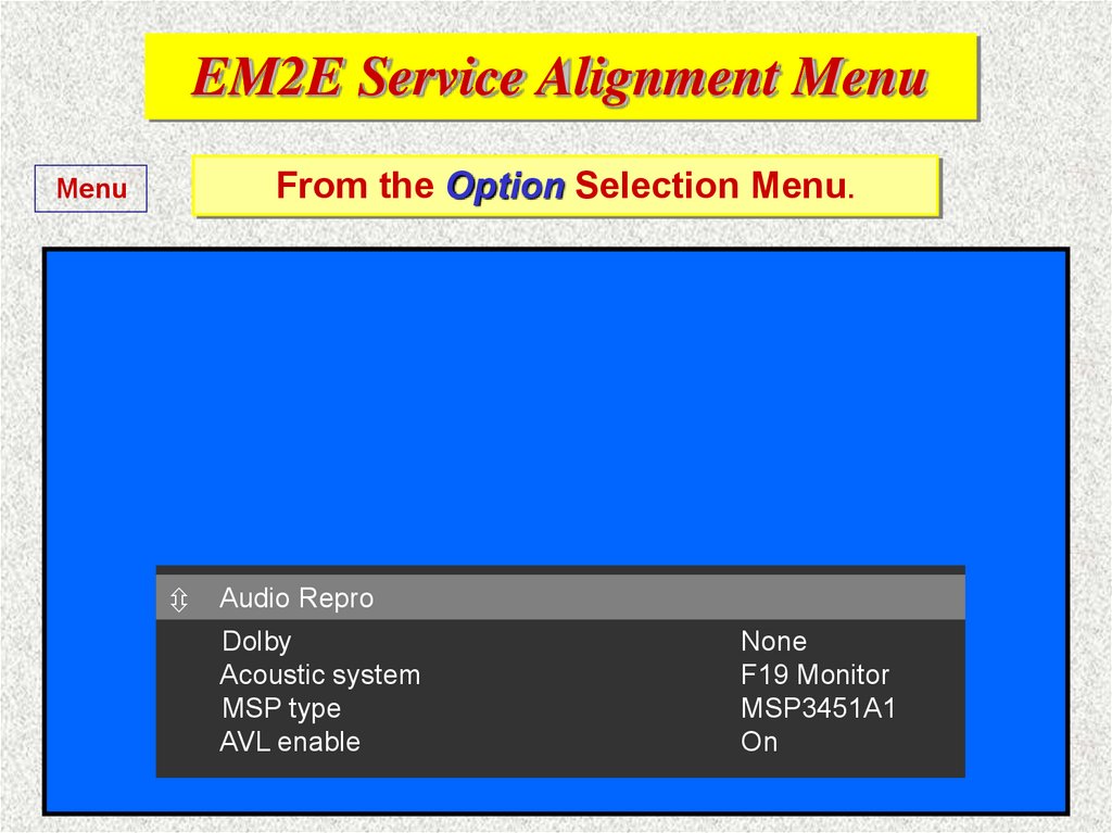
EM2E Service Alignment MenuFrom the Option Selection Menu.
Menu
Audio Repro
Dolby
Acoustic system
MSP type
AVL enable
None
F18
MSP3451A1
On
43.
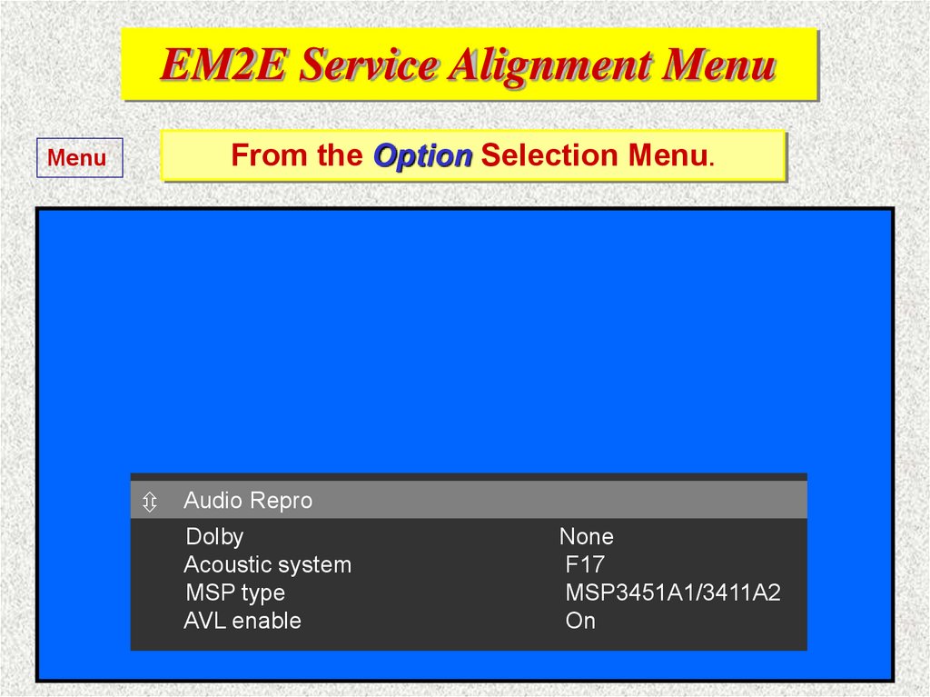
EM2E Service Alignment MenuFrom the Option Selection Menu.
Menu
Audio Repro
Dolby
Acoustic system
MSP type
AVL enable
None
F17
MSP3451A1/3411A2
On
44.
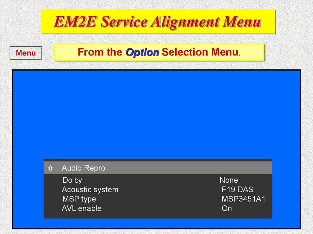
EM2E Service Alignment MenuFrom the Option Selection Menu.
Menu
Audio Repro
Dolby
Acoustic system
MSP type
AVL enable
None
F19 DAS
MSP3451A1
On
45.
EM2E Service Alignment MenuFrom the Option Selection Menu.
Menu
Audio Repro
Dolby
Acoustic system
MSP type
AVL enable
None
F19 Monitor
MSP3451A1
On
46.
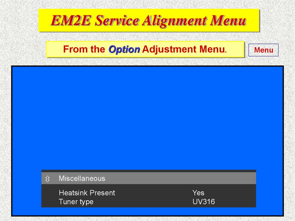
EM2E Service Alignment MenuFrom the Option Adjustment Menu.
TXT
OPTIONS
Miscellaneous
Heatsink Present
Tuner type
Yes
UV316
Menu
47.
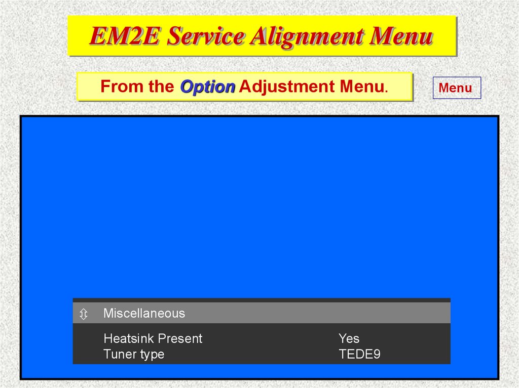
EM2E Service Alignment MenuFrom the Option Adjustment Menu.
TXT
OPTIONS
Miscellaneous
Heatsink Present
Tuner type
Yes
TEDE9
Menu
48. EM2E Chassis service modes SM 3122 785 10310
§ 5.2Service Modes
5.2.1 Service Default Mode (SDM)
Menu
Page 19
Can be activated by RC by dialling ‘062596’ + ‘MENU’,
by ComPair / DST or short-circuiting item 4006 on SSB.
N.B.
*
*
*
*
*
In this mode all TV settings are fixed (default) as follows!
Tuned frequency 475.25 MHz
TV-systems for BGLM sets are set to BG
Picture settings (contrast, brightness, colour & hue are
set to 50% value.
All sound settings to 50% value except volume to 25%
All service unfriendly modes are disabled (like sleep timer,
child lock, blue mute, AVL and SDLP).
49. EM2E Chassis service modes SM 3122 785 10310
§ 5.2Service Modes
Next
5.2.3 Customer Service Mode (CSM)Page 19
To activate it, press simultaneously the ‘MUTE’ key on RC
and the ‘MENU’ key on the TV set minimum of 4 seconds.
This menu is meant to show the actual TV settings and
other functional information for a customer if requested by
service when ‘a fault or a malfunction’ has occurred.
This CSM menu is read only menu, so NO modification to
any settings can be done by this menu.
50. EM2E Chassis service modes SM 3122 785 10310
§ 5.2Service Modes
Next
5.2.3 Customer Service Mode (CSM)Page 19
CUSTOMER SERVICE MENU 1
1
SW Version
EM2E_11.5_02431
2
3
4
5
6
7
8
9
10
11
11a
Code 1 (error code)
Code 2 (error code)
LS Volume
LS Brightness
LS Contrast
LS Colour
LS Headphone
Sharpness
Dolby
Surround mode
Tuner Frequency
No Errors
7
28
48
31
12
3
0
203 MHz
51. EM2E Chassis service modes SM 3122 785 10310
§ 5.2Service Modes
Menu
5.2.3 Customer Service Mode (CSM)Page 21
CUSTOMER SERVICE MENU 2
13
Centre Volume
11
14
15
16
17
18
19
20
21
22
DNR
Noise Figure
Digital Option
Colour System
TV System
Audio System
Tuned Bit
Speaker Config.
Digital Sources
Off
15 Range 0 - 255, 0 = no noise, 255 = noise
Digital Scan
PAL
BG
NICAM
Off
0
None
Important for DVD
52. EM2E Chassis service modes SM 3122 785 10310
5.2Service Modes
Next
5.4
ComPair
5.4.1
ComPair (Computer Aided Repair) is a service tool
Page 24
for PHILIPS Consumer Electronics products.
ComPair is the most advanced service tool
offered at the present time to assist in faultfinding in complex electronic products.
(DST, RC7150 was the prior service tool)
53. EM2E Chassis service modes SM 3122 785 10310
§ 5.2Service Modes
Return
5.4
ComPair
5.4.3
Stepwise start-up / Shutdown (power supply)
Page 24
This function is only possible with ComPair.
Stepwise start-up explanation.
See the text!
Stepwise shutdown explanation. See the text!
N.B.
5.7.2
For more repair tips see page 28!
ComPair demo
54. EM2E Chassis service modes SM 3122 785 10310
§ 5.2Service Modes
5.4.2 SearchMan
Return
(Electronic Service Manual)
Page 23
If you have installed ComPair and SearchMan in
your computer (PC) you will have immediate
access to diagrams and PCB lay-outs. Ordering
codes of components will be found without any
loss of time. The SearchMan program (engine) is
supplied on one CD-ROM disc and up-date
Service Manuals are available on two other
CD-ROM disc. Five different product groups are
supported by this system.
SearchMan info
55. EM2E Chassis service modes SM 3122 785 10310
5.5.3Error Code Table
Error Device
1
2
3
4
5
6
7
8
9
11
12
13
14
15
16
Next
ST24E32
H fail protection
SAA4978
Supply 5 V
Supply 8 V
2
Slow I C-bus blocked
TDA9330
TDA9320
X-ray protection
HOP protection
Tuner protection
UV1316
MSP3451/3415
Flash protection
Featurebox protection
Page 25
Description
Def. Item Diagr. Defect module
NVM
HFB
PICNIC
5V2
8V6
IC7011
B5
IC7709
B3
HOP video contr./geom. IC7301
HIP I/O video process IC7323
B4
B2
Control
Horizontal feedback
Feature Box
+5 V Supply
+8 V Supply
2
Slow I C blocked
Video Controler
Chroma IF IO
TUNER_PROT
Tuner
ITT sound proc. Dolby
A7
B6
+8 V (Tuner) Supply
Audio Module
FBX_PROT
U1200
IC7651
56. EM2E Chassis service modes SM 3122 785 10310
§ 5.2Service Modes
Return
5.5 Error Codes
Page 24
5.5.1 Reading error codes from the buffer. With DST
Try inthese
The error codes are shown
SAM, 10 codes in two rows, and
the selected one is displayed in SDM by blinking standby LED
If for example the following error codes are found:
Error position;
1
2
3
4
5
Error Codes:
12
9
5
0
0
This is what we can read from the buffer.
The latest error is in position 1, next in pos. 2 etc.
57. EM2E Chassis service modes SM 3122 785 10310
§ 5.2Service Modes
Return
5.5 Error Codes
Page 24
5.5.1 Reading error codes from the buffer
The
standby
LED
10
12
11
IfInthe
first
error
chosen……then..
this
case
we position
read the is
error
code 12 which means
The
standby
LED will blink the value of the error code..
Tuner
protection..
Error position;
1
--------------Error Codes:
12
2
9
3
5
4
0
5
0
A long blink means (ten) and short blinks (units).
The error code is repeated until the set is shut off.
58. EM2E Chassis service modes SM 3122 785 10310
§ 5.2Service Modes
Return
5.5 Error Codes
Page 24
5.5.1 Reading error codes from the buffer
The
standby
LED
9
8
7
6
5
4
3
2
1
So ifinyou
Or
thischoose
case wethe
read
second
the error
errorcode
position…...
9, which means
The standby
X-ray
protection
LED will blink the value of the error code..
Error position;
1
-------------------Error Codes:
12
2
9
3
5
4
0
5
0
A long blink means (ten) and short blinks (units).
The error code is repeated until the set is shut off.
59. EM2E Chassis service modes SM 3122 785 10310
§ 5.2Service Modes
Return
5.5 Error Codes
Page 24
5.5.1 Reading error codes from the buffer
The
standby
LED
5
4
3
2
1
Or
Inifthis
youcase
choose
the error
the third
code
error
is 5 position…...
which means,
The
+8 V
standby
Supply.LED will blink the value of the error code..
Error position;
1
2
-----------------------Error Codes:
12 9
3
5
4
0
5
0
A long blink means (ten) and short blinks (units).
The error code is repeated until the set is shut off.
60. EM2E Chassis service modes SM 3122 785 10310
§ 5.2Service Modes
Return
5.5 Error Codes
Page 24
5.5.1 Reading error codes from the buffer
The
standby
LED
If you choose any other error position which contains
zero (0). The standby LED will NOT blink..
Error position;
1
2
3
-----------------------------Error Codes:
12 9
5
4
0
5
0
or..
A long blink means (ten) and short blinks (units).
(In this case the DST display will stay blanked).
61. EM2E Chassis service modes SM 3122 785 10310
§ 5.2Service Modes
Next
5.5 Error Codes with DST
Page 24
Always start faultfinding with DST like this;
1. Press the ’Diagnose’ button on the DST!
2. Press the digit keys ’99’!
3. Press the ’OK’ key!
Now the DST transmits a code to erase all error codes
in the set. Switch off the set with the mains switch and
start it again with the mains switch. Wait until the
standby LED starts blinking!
62. EM2E Chassis service modes SM 3122 785 10310
§ 5.2Service Modes
5.5 Error Codes
Page 24
5.5.1 Reading error codes with DST from the buffer
Start
Startreading
reading
the
the
error
error
codes
codes
from
from
the
position
Write
down
the
error
code
from
theposition
position
one
number
numberone
one!!
Error position;
--------------- 1
Error Codes:
12
2
9
3
5
4
0
5
0
If you use DST for fault finding read all error codes
from the left to the right until the first zero is found!
63. EM2E Chassis service modes SM 3122 785 10310
§ 5.2Service Modes
5.5 Error Codes
Page 24
5.5.1 Reading error codes with DST from the buffer
Read
Writethe
down
error
thecode
errorfrom
codethe
number
position
twotwo
! !
Error position;
1
-------------------Error Codes:
12
2
9
3
5
4
0
5
0
If you use DST for fault finding read all error codes
from the left to the right until the first zero is found!
64. EM2E Chassis service modes SM 3122 785 10310
§ 5.2Service Modes
5.5 Error Codes
Page 24
5.5.1 Reading error codes with DST from the buffer
Read
Writethe
down
error
thecode
errorfrom
codethe
number
position
three
three
! !
Error position;
1
2
------------------------Error Codes:
12
9
3
5
4
0
5
0
If you use DST for fault finding read all error codes
from the left to the right until the first zero is found!
65. EM2E Chassis service modes SM 3122 785 10310
§ 5.2Service Modes
Return
5.5 Error Codes
Page 24
5.5.1 Reading error codes with DST from the buffer
Now, we have found the first zero and can start looking
Read
from the
position
four !
for thethe
faulterror
from code
the rightmost
error
code position,
which is in this case position 3, error 5 = +8V Supply !
Error position;
1
2
3
4
------------------------------Error Codes:
12
9
5
0
5
0
If you use DST for fault finding read all error codes
from the left to the right until the first zero is found!
66.
Service ManualHere you will find
the chassis type=
EM2 E = Europe
A = Asia
U back
= USA
Use this
cover
Return
label information to
select the correct
These
letters
Service two
Manual
to
show
chassis
be usedthe
during
your
repair.
version, evolution
In this corner we
find info about
language and
ordering code
GB
I
3122 785 10310
67.
The back cover labelE
The
EM2
means,
box
letter
means
here
S
this
means
the
contains
chassis
chassis
Service!
isservice
in
forthe
Europe!
set!
information!
The
AA
means
the
chassis
version!
Next
68.
The picture tube stickerOptioncode :
The option codes of the set
If you change the picture tube
of the set, you have to move
this sticker to the new picture
tube or write a new sticker with
option codes. It is necessary
that this information follows the
TV set untill it will be rejected
to recycling.
Return
04865 04356 04928 00017
12343 00001 00000 00064
max. EHT : 29
kV
max. Beam Curr. : 1.8 mA
IE
32PW8506/12
AG000034 002149
220 - 240V ~50Hz
VHF+S+H+UHF
MADE IN BELGIUM
105W
69.
and serviceThe
Two
one
locking
position,
snap
hooks
hook
on
the5left
right
about
cm
side!
backwards!
Option code
sticker!
Return
70.
EM2E Service Alignment MenuThe Normal Geometry Adjustment Menu.
Horizontal bow
4
Menu
71.
EM2E Service Alignment MenuThe Normal Geometry Adjustment Menu.
Horizontal bow
5
Menu
72.
EM2E Service Alignment MenuThe Normal Geometry Adjustment Menu.
Horizontal bow
6
Menu
73.
EM2E Service Alignment MenuThe Normal Geometry Adjustment Menu.
Horizontal bow
7
Return
74.
EM2E Service Alignment MenuThe Normal Geometry Adjustment Menu.
Horizontal bow
8
Menu
75.
EM2E Service Alignment MenuThe Normal Geometry Adjustment Menu.
Horizontal bow
9
Menu
76.
EM2E Service Alignment MenuThe Normal Geometry Adjustment Menu.
Horizontal bow
10
Menu
77.
EM2E Service Alignment MenuThe Normal Geometry Adjustment Menu.
Horizontal bow
11
Menu
78.
EM2E Service Alignment MenuThe Normal Geometry Adjustment Menu.
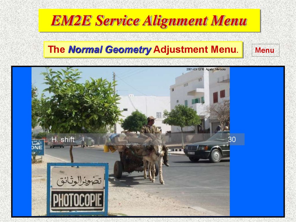
2001-03-12/16 Agadir, Marocko
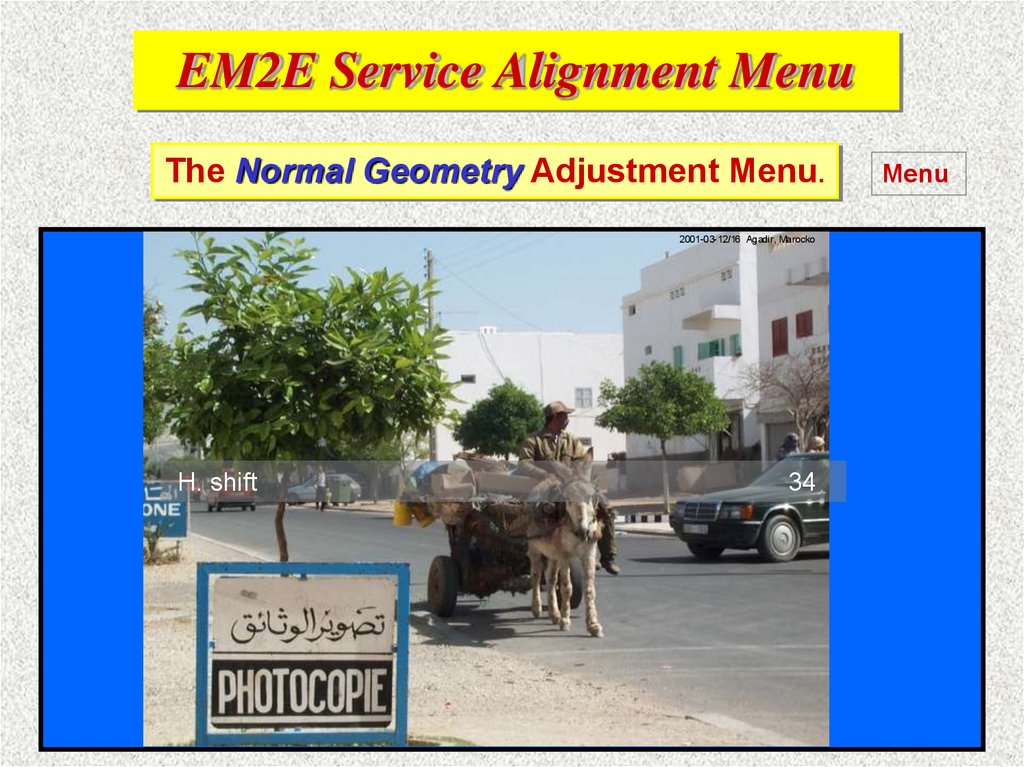
H. shift
30
Menu
79.
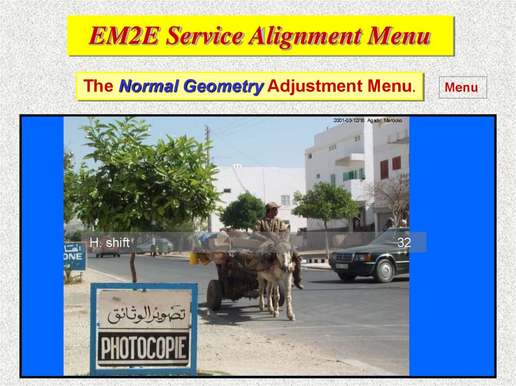
EM2E Service Alignment MenuThe Normal Geometry Adjustment Menu.
2001-03-12/16 Agadir, Marocko
H. shift
32
Menu
80.
EM2E Service Alignment MenuThe Normal Geometry Adjustment Menu.
2001-03-12/16 Agadir, Marocko
H. shift
34
Menu
81.
EM2E Service Alignment MenuThe Normal Geometry Adjustment Menu.
2001-03-12/16 Agadir, Marocko
H. shift
36
Menu
82.
EM2E Service Alignment MenuThe Normal Geometry Adjustment Menu.
Menu
2001-03- 12/16 Agadir, Marocko
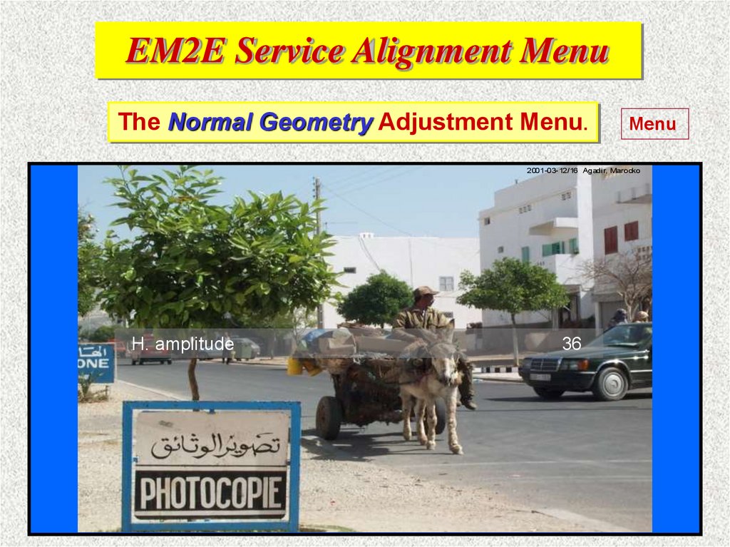
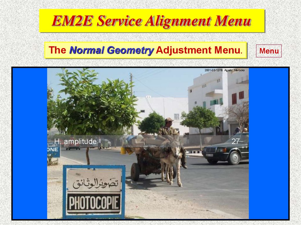
H. amplitude
36
83.
EM2E Service Alignment MenuThe Normal Geometry Adjustment Menu.
2001-03- 12/16 Agadir, Marocko
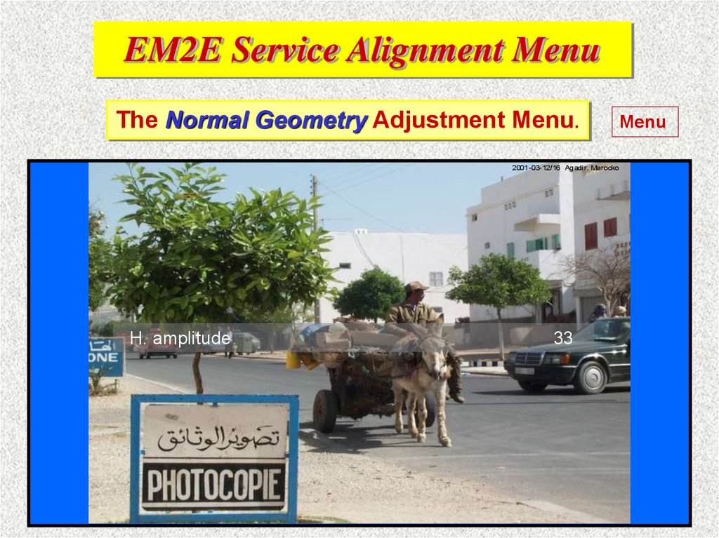
H. amplitude
33
Menu
84.
EM2E Service Alignment MenuThe Normal Geometry Adjustment Menu.
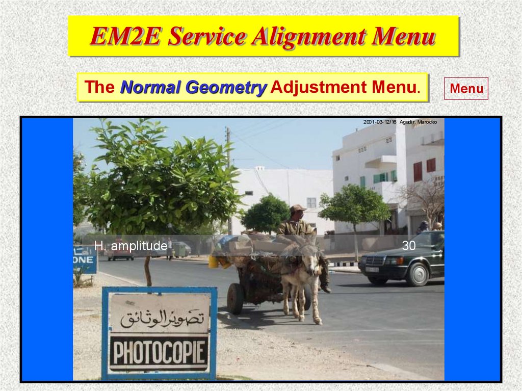
2001-03- 12/16 Agadir, Marocko
H. amplitude
30
Menu
85.
EM2E Service Alignment MenuThe Normal Geometry Adjustment Menu.
2001-03-12/16 Agadir, Marocko
H. amplitude
27
Menu
86.
EM2E Service Alignment MenuThe Normal Geometry Adjustment Menu.
Normal Geometry
Test Pattern
V. Slope
H. shift
H. amplitude
East/West Parabola
Upper East/West corner
Lower East/West corner
East/West Trapezium
Horizontal parallellogram
Horizontal bow
On
42
36
27
15
33
28
32
8
8
Menu
87.
EM2E Service Alignment MenuThe Normal Geometry Adjustment Menu.
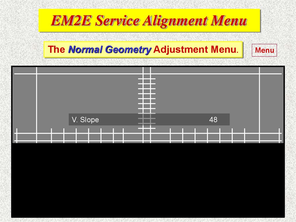
V. Slope
48
Menu
88.
EM2E Service Alignment MenuThe Normal Geometry Adjustment Menu.
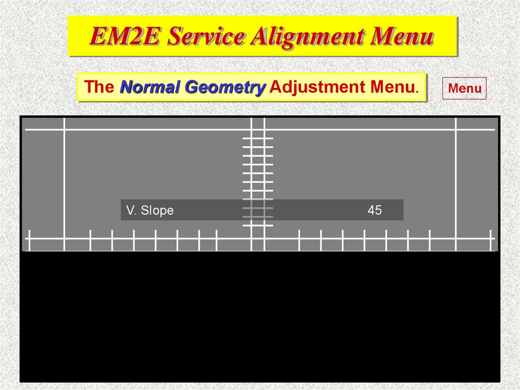
V. Slope
45
Menu
89.
EM2E Service Alignment MenuThe Normal Geometry Adjustment Menu.
V. Slope
42
Menu
90.
EM2E Service Alignment MenuThe Normal Geometry Adjustment Menu.
V. Slope
39
Menu
91.
EM2E Service Alignment MenuThe Normal Geometry Adjustment Menu.
V. Slope
42
Menu
92.
EM2E Service Alignment MenuThe Normal Geometry Adjustment Menu.
East/West Parabola
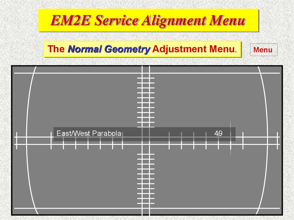
49
Menu
93.
EM2E Service Alignment MenuThe Normal Geometry Adjustment Menu.
East/West Parabola
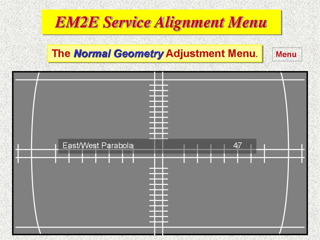
47
Menu
94.
EM2E Service Alignment MenuThe Normal Geometry Adjustment Menu.
East/West Parabola
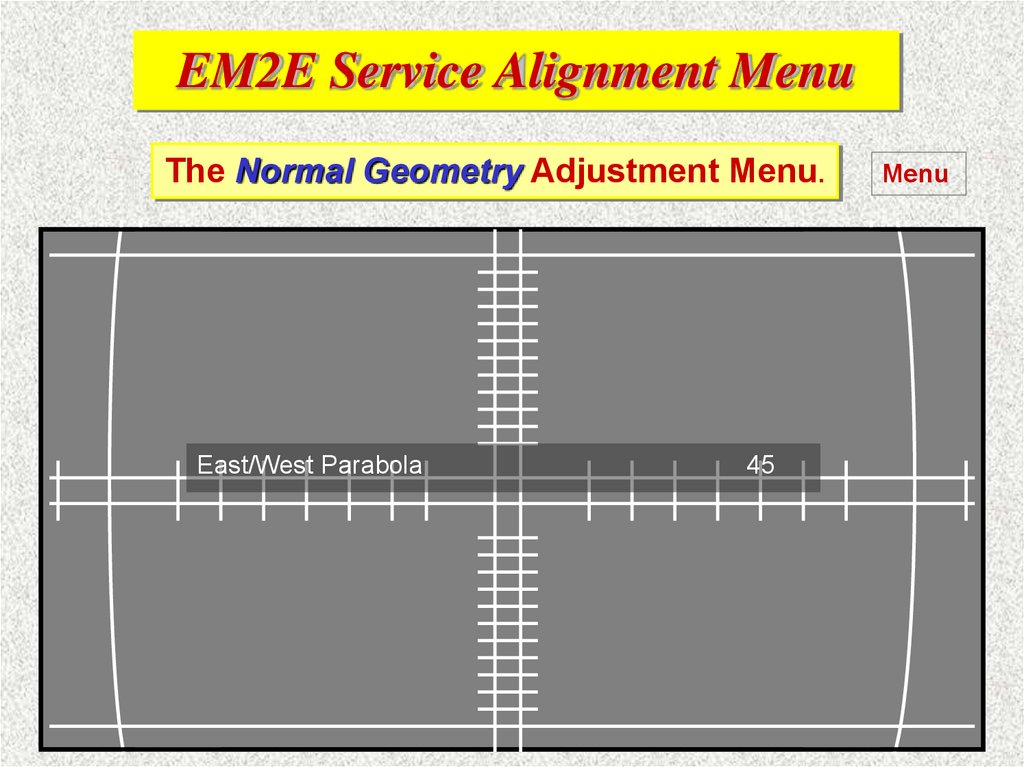
45
Menu
95.
EM2E Service Alignment MenuThe Normal Geometry Adjustment Menu.
East/West Parabola
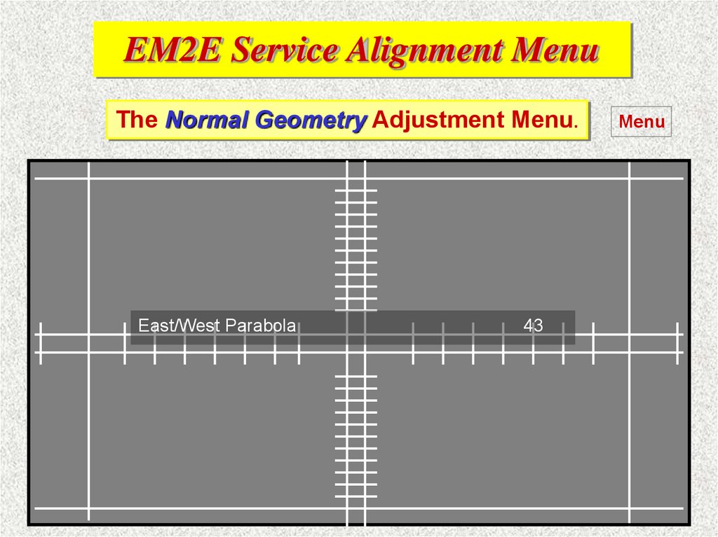
43
Menu
96.
EM2E Service Alignment MenuThe Normal Geometry Adjustment Menu.
East/West Parabola
41
Menu
97.
EM2E Service Alignment MenuThe Normal Geometry Adjustment Menu.
East/West Parabola
39
Menu
98.
EM2E Service Alignment MenuThe Normal Geometry Adjustment Menu.
East/West Parabola
37
Menu
99.
EM2E Service Alignment MenuThe Normal Geometry Adjustment Menu.
Upper East/West corner
11
Menu
100.
EM2E Service Alignment MenuThe Normal Geometry Adjustment Menu.
Upper East/West corner
10
Menu
101.
EM2E Service Alignment MenuThe Normal Geometry Adjustment Menu.
Upper East/West corner
9
Menu
102.
EM2E Service Alignment MenuThe Normal Geometry Adjustment Menu.
Upper East/West corner
8
Menu
103.
EM2E Service Alignment MenuThe Normal Geometry Adjustment Menu.
Upper East/West corner
7
Menu
104.
EM2E Service Alignment MenuThe Normal Geometry Adjustment Menu.
Upper East/West corner
6
Menu
105.
EM2E Service Alignment MenuThe Normal Geometry Adjustment Menu.
Upper East/West corner
5
Menu
106.
EM2E Service Alignment MenuThe Normal Geometry Adjustment Menu.
Lower East/West corner
13
Menu
107.
EM2E Service Alignment MenuThe Normal Geometry Adjustment Menu.
Lower East/West corner
12
Menu
108.
EM2E Service Alignment MenuThe Normal Geometry Adjustment Menu.
Lower East/West corner
11
Menu
109.
EM2E Service Alignment MenuThe Normal Geometry Adjustment Menu.
Lower East/West corner
10
Menu
110.
EM2E Service Alignment MenuThe Normal Geometry Adjustment Menu.
Lower East/West corner
9
Menu
111.
EM2E Service Alignment MenuThe Normal Geometry Adjustment Menu.
Lower East/West corner
8
Menu
112.
EM2E Service Alignment MenuThe Normal Geometry Adjustment Menu.
Lower East/West corner
7
Menu
113.
EM2E Service Alignment MenuThe Normal Geometry Adjustment Menu.
East/West Trapezium
23
Menu
114.
EM2E Service Alignment MenuThe Normal Geometry Adjustment Menu.
East/West Trapezium
26
Menu
115.
EM2E Service Alignment MenuThe Normal Geometry Adjustment Menu.
East/West Trapezium
29
Menu
116.
EM2E Service Alignment MenuThe Normal Geometry Adjustment Menu.
East/West Trapezium
32
Menu
117.
EM2E Service Alignment MenuThe Normal Geometry Adjustment Menu.
East/West Trapezium
35
Menu
118.
EM2E Service Alignment MenuThe Normal Geometry Adjustment Menu.
East/West Trapezium
38
Menu
119.
EM2E Service Alignment MenuThe Normal Geometry Adjustment Menu.
East/West Trapezium
41
Menu
120.
EM2E Service Alignment MenuThe Normal Geometry Adjustment Menu.
East/West Parallelogram
9
Menu
121.
EM2E Service Alignment MenuThe Normal Geometry Adjustment Menu.
East/West Parallelogram
11
Menu
122.
EM2E Service Alignment MenuThe Normal Geometry Adjustment Menu.
East/West Parallelogram
13
Menu
123.
EM2E Service Alignment MenuThe Normal Geometry Adjustment Menu.
East/West Parallelogram
15
Menu
124.
EM2E Service Alignment MenuThe Normal Geometry Adjustment Menu.
East/West Parallelogram
17
Menu
125.
EM2E Service Alignment MenuThe Normal Geometry Adjustment Menu.
East/West Parallelogram
19
Menu
126.
EM2E Service Alignment MenuThe Normal Geometry Adjustment Menu.
East/West Parallelogram
21
Menu