


 physics
Similar presentations:


Radiographic testing
1.
RADIOGRAPHIC TESTINGPrepared by students: Khalafov R.,
Zelentsov D., Madaminov N.,
Kunashenko S.
Tomsk 2018
2.
Content2
Introduction
Theory and principles
Radiographic equipment and accessories
Variables
Techniques and procedures
Radiographic evaluation
Applications
Advantages and limitations of radiography
3. Introduction
3• This presentation shows information about the NDT
method of radiographic inspection or radiography.
• Radiography uses penetrating radiation that is directed
towards a component.
• The component stops some of the radiation. The
amount that is stopped or absorbed is affected by
material density and thickness differences.
• These differences in “absorption” can be recorded on
film, or electronically.
4. Theory and principles
4Radiation is Absorbed and Scattered by Material
5.
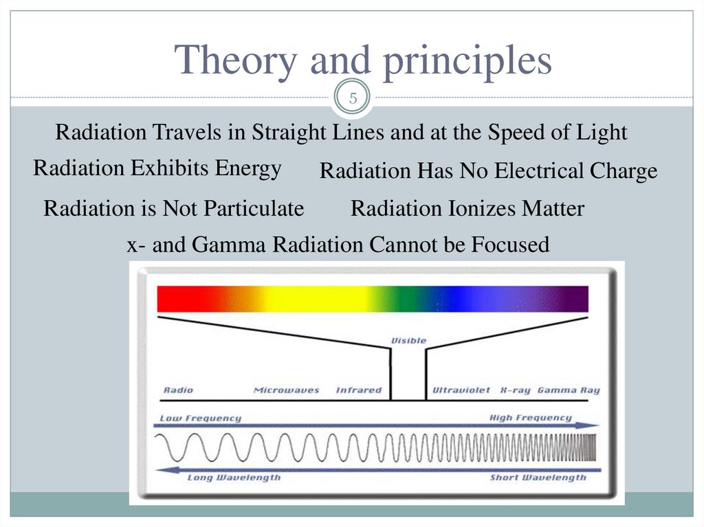
Theory and principles5
Radiation Travels in Straight Lines and at the Speed of Light
Radiation Exhibits Energy
Radiation is Not Particulate
Radiation Has No Electrical Charge
Radiation Ionizes Matter
x- and Gamma Radiation Cannot be Focused
6. General Principles of Radiography
6The part is placed between the radiation
source and a piece of film. The part will stop
some of the radiation. Thicker and more
dense area will stop more of the radiation.
X-ray film
The film darkness (density)
will vary with the amount
of radiation reaching the
film through the test object.
= less exposure
= more exposure
Top view of developed film
7. General Principles of Radiography
7• The energy of the radiation affects its penetrating power.
Higher energy radiation can penetrate thicker and more
dense materials.
The radiation energy and/or exposure time must be
controlled to properly image the region of interest.
Thin Walled Area
Low Energy Radiation
High energy Radiation
8. Gamma Radiography
8• Gamma rays are produced by
a radioisotope.
• A radioisotope has an unstable
nuclei that does not have
enough binding energy to hold
the nucleus together.
• The spontaneous breakdown
of an atomic nucleus resulting
in the release of energy and
matter is known as radioactive
decay.
9. Gamma Radiography
9Unlike X-rays, which are produced
by a machine, gamma rays cannot be
turned off. Radioisotopes used for
gamma radiography are encapsulated
to prevent leakage of the material.
The radioactive “capsule” is
attached to a cable to form what is
often called a “pigtail.”
The pigtail has a special connector
at the other end that attaches to a
drive cable.
10. Gamma Radiography
10A device called a “camera” is used to store, transport and
expose the pigtail containing the radioactive material. The
camera contains shielding material which reduces the
radiographer’s exposure to radiation during use.
11. Gamma Radiography
11A hose-like device called
a guide tube is connected
to a threaded hole called
an “exit port” in the
camera.
The radioactive material
will leave and return to
the camera through this
opening when performing
an exposure!
12. Gamma Radiography
12A “drive cable” is connected to the
other end of the camera. This cable,
controlled by the radiographer, is
used to force the radioactive
material out into the guide tube
where the gamma rays will pass
through the specimen and expose
the recording device.
13. X-ray Radiography
13Unlike gamma rays, x-rays are produced by an X-ray generator
system. These systems typically include an X-ray tube head, a
high voltage generator, and a control console.
14. X-ray Radiography
14• X-rays are produced by establishing a very high voltage between
two electrodes, called the anode and cathode.
• To prevent
arcing, the anode and cathode are located inside a
vacuum tube, which is protected by a metal housing.
15. Variables of radiography
15Of all the nondestructive testing methods, radiography
certainly has the most variables. These variables include:
• Energy
• Exposure time
• mA (x-ray) or curies (gamma
ray)
• Material type and density
• Material thickness
• Type of film
• Screens used
• Film processing
• Film density
• Distance from rad. Source to
the object
• Distance from the object to
the film
• Physical size of the target (xray) or source (gamma ray)
16. Variables of radiography
16In order to control these variables so that the benefits
can be maximized for each one, a technique chart
should be used. Unfortunately, there are still many
radiographs taken by the “trial and error” technique.
The best way to produce a high-quality radiograph is
through the use of exposure charts
17. Using of exposure charts
17X-ray
1. Verify the material type
2. Project a straight line
vertically from that
thickness up to the top of
the technique chart and
notice that there are a
number of energies that can
be used
3. Choose the exposure time
and intensity combined in
units of milliampere
seconds (mAs)
18. Using of exposure charts
18Gamma ray
1. To project the material
thickness vertically until it
intersects with the film type
being used
2. Draw a line horizontally to
the vertical axis. From that
axis, the exposure factor
(EF) is determined.
3. An exposure time in
minutes can be easily
calculated by the equation
19. Source to film distance
19Source to film distance (SFD) is also referred to as
the target to film distance (TFD). The TFD generally
applies when using an x-ray source and the SFD
applies when radioactive isotopes are used.
There is a mathematical relationship between the
exposure time and the distance:
T1 = original exposure time
derived from the technique
chart
T2 = new exposure time
D1 = original distance
D2 = new distance
20. Techniques and procedures
20Single wall exposure, single view technique
21. Techniques and procedures
21Double wall exposure, single view technique
Double wall exposure, double view technique
22. Procedure
22Understand the codes, specifications, and customer requirements thoroughly
Develop a technique based on the thickness and type of material
Prepare a shooting sketch
In the darkroom, carefully place the radiographic film in the cassette with the
proper lead screens
Place the film under the area of interest
Ensure that the correct source to film distance is being employed
Place the appropriate station markers and identification numbers in the area of
interest to assure easy correlation with a discontinuity if one is detected
Set up the exposure parameters
Make the exposure
In the darkroom, unload and process the film
Evaluate the film for artifacts
Evaluate the film for compliance
Complete a report and store the film
23. Radiographic Film
23Class I is described as extra-fine grain, low speed, with very high
contrast capabilities. This film is generally used for lower-density
materials and can be used with or without lead screens.
Class II is a fine-grain, medium-speed, high-contrast film that is
also used for the lower-density materials with low- and mediumenergy radiation. This film classification tends to be more widely
used than the Class I since it provides very good definition, has
fine grain, and is slightly higher in film speed than Class I. It can
also be used with or without lead screens.
Class III is a high-speed film, and therefore requires shorter
exposure times. It is typically used for x-rays or gamma rays with
higher energies, and can be used with or without lead screens. It is
considered a medium-contrast film with high graininess.
24. Film processing
24Developing Developers are alkaline solutions that change the
latent or chemically stored image in the radiographic emulsion
into a visible image, resulting in various shades of gray or black
Stop developing The film can be taken out of the developer and
placed into a water bath for several minutes, or it can be placed in
an acidic solution called stop bath
Fixing Fixer clears out the unexposed silver halide crystals
remaining in the film and, second, it fixes or hardens the image.
After fixing, the film goes into a water rinse for a period of time,
typically 30 minutes in order to remove any remaining traces of
the developer or the fixer
Drying the film Normally done in a warm air recirculating drier
designed for this purpose
25. Density of the film
25Film density is defined as the quantitative measure of film blackening as a result
of exposure and processing
It can be expressed mathematically as follows:
where: D = density I0 = light incident on the film It = light intensity transmitted
through the film
If a film is exposed and the resultant film density is one, the amount of light that
passes through the film is 10% of the incident light. For a film density of 2.0,
only 1% of the incident light passes through. A film density of 3.0 permits 0.1%
of the incident light to pass through, a film density of 4.0, 0.01%, and so on.
26. Radiographic evaluation
26• Interpretation
of radiographs requires hours of reviewing and
understanding the different types of images.
The radiographic interpreter should always wear cloth gloves
(preferably cotton) when evaluating radiographs.
Magnifiers are encouraged when they can assist in the proper
detection and identification of the different discontinuities.
27. Image Quality
27• Image
quality is critical for accurate assessment of a test
specimen’s integrity.
Various tools called Image Quality Indicators (IQIs) are used for
this purpose.
There are many different designs of IQIs. Some contain
artificial holes of varying size drilled in metal plaques while
others are manufactured from wires of differing diameters
mounted next to one another.
28. Image Quality
28• IQIs are typically placed
on or next to a test
specimen.
Quality typically being
determined based on the
smallest hole or wire
diameter that is reproduced
on the image.
29. Evaluation for Artifacts
29Artifact - a false indication on a radiograph arising from, but
not limited to, faulty manufacture of the film, storage,
handling, exposure, or processing.
Film artifacts that are caused
prior to processing
Lead screen marks
Static marks
Film scratches
Exposure to light
Fog due to exposure to low
levels of light or aging
• Finger marks
• Pressure marks
• Crimp marks
Artifacts that are caused during
the processing of the Film
• Pressure marks (from rollers in
an automatic processor)
• Chemical and delay streaks
• Pi lines (in automatic
processors)
• Chemical spots
• Dirt
30. Evaluation for Discontinuities
30Discontinuity conditions that are normally found in welds include
those in the following subsections, listed in order of severity.
Cracks
There are many different types of cracks that are classified by
their orientation and location. They will always appear as dark,
irregular, linear indications in a radiograph and are the most
serious of all discontinuities.
31. Evaluation for Discontinuities
31Lack of Fusion
This serious discontinuity results from an absence of metallurgical
fusion, either between a weld pass and the base material (weld
edge prep) or between two successive weld passes. Lack of fusion
is usually very narrow, linear, and tends to be straighter than the
crack.
32. Evaluation for Discontinuities
32Incomplete Penetration
This discontinuity is an absence of weld metal or an area of
“nonfusion” in the root pass of the weld. Its appearance is very
straight, dark, linear, and usually “crisp” in sharpness.
33. Evaluation for Discontinuities
33Inclusions (Dense and Less Dense)
Inclusions are basically materials that have been entrapped in the weld that do
not belong there. They will have a variety of shapes and dimensions ranging
from short and isolated to linear and numerous. The lighter-density inclusions
will result in a darker image on the radiograph and the more dense inclusions,
such as tungsten, as a lighter image.
34. Evaluation for Discontinuities
34Porosity
When gas is trapped in a weld metal, the void-type condition created is referred
to as gas or porosity. Porosity comes in different shapes (globular, tailed,
elongated) and distributions (linearly aligned, clustered, isolated, scattered).
Porosity will always appear darker, since they are gas filled, and are the easiest
of all weld discontinuities to detect.
35. Geometric Conditions
35There are also geometric conditions that can occur in welds that
are observable in a radiograph and should be further addressed by
visual examination and dimensional checks.
These geometric conditions include the following: concavity,
convexity, undercut, underfill and overreinforcement.
36. Casting Discontinuities
36Hot tears and cracks
Hot tears and cracks – both serious ruptures or fissures that
typically occur in an isolated zone due to the high stresses that
build up during the cooling of the casting. On a radiograph, both
conditions appear linear and branch-like and are most likely to be
in or near an area of thickness change, where the different rates of
cooling cause stresses to build up.
37. Casting Discontinuities
37Shrinkage
Shrinkage – usually in the form of a zone of minute fissures as a
result of stresses during cooling. Shrinkage comes in various
shapes. Microshrinkage is feathery in appearance and the change
in density is often quite minor.
38. Casting Discontinuities
38Slag and sand inclusions
Slag and sand inclusions – the entrapment of inclusion materials
and sand cause these conditions, which will have irregular shapes
and variations in density due to the nature of the included matter.
39. Casting Discontinuities
39Gas voids and porosity
Gas voids and porosity – unlike the inclusions, gas voids and
porosity are more uniform, typically globular and dark in
appearance. In fact, these discontinuities just look like voids, are
normally easy to detect (they are not subject to alignment
limitations like cracks), and readily recognizable.
40. Casting Discontinuities
40Cold shuts
Cold shuts – very tight discontinuities that occur when a surface
that has begun to solidify comes in contact with other molten
metal as the casting is in the process of being poured. There is
usually a thin film of oxide present that prevents total
metallurgical fusion. It is a very difficult discontinuity to detect
with radiography
41. Geometric Conditions
41There are also geometric conditions in castings that can be
observed radiographically.
These geometric conditions include the following: misrun, unfused
chaplets.
Misrun – this condition
is actually an absence of
metal due to the
inadequate filling of the
casting mold. It is easily
detected by a simple
visual test.
42. Applications
42Although the majority of applications in radiographic testing appear to
involve welds and castings, it has been effectively applied to many other
product forms spanning a wide variety of industries. The major industries
include following.
43. Advantages of Radiography
43Provides an extremely accurate and permanent
record
Is very versatile and can be used to examine many
shapes and sizes
Is quite sensitive, assuming the discontinuity
causes a reasonable reduction of cross section
thickness
Permits discontinuity characterization
Is widely used and time-proven
Is a volumetric NDT method
44. Limitations
441. There are safety hazards with the use of radiation devices
2. RT has thickness limitations, based on material density and
energy used
3. RT can be time-consuming
4. RT is very costly in initial equipment and expendable
materials
5. It is also very dependent on discontinuity orientation
6. RT requires extensive experience and training of the
personnel taking the radiographs and during the interpretation