


 physics
 warfare
Similar presentations:


")


EMI introduction & Coupling modes in EMI 2018-V1
1.
Electromagnetic immunity2.
Schedule_ Introduction
_ Electromagnetic environment
_ How to take EMI into account
_ How to evaluate EM attacks
- radiated attacks
- drived (or led) attacks
_ Vulnerability and agressivity of equipments
- radiated perturbations
- driven perturbations
- Protection
- against radiated attacks
- against driven attacks
3.
EMI : Context & stakesContext :
Noisy environment owing to :
More devices in an always more small volume
Working frequencies always higher
Supplying voltages always smaller: more sensitivity to
perturbations
Total system power consumptions always more and more
higher
Stakes :
To
limit or to avoid :
Minor dysfonctionments
Components destruction
Example : radio confusing
Example : loss of fonctionality
system destruction
Aware to security, risk of dead or injury in accidents !!
3
4.
5.
Example: 1967: VIETNAMUSS Forestal disaster
A missile had been launched and
directed towards aircraft carrier due to a
parasite on supplying voltage
An aircraft carrier completely destroyed,
tenths of dead people, several million $
of damages.
6.
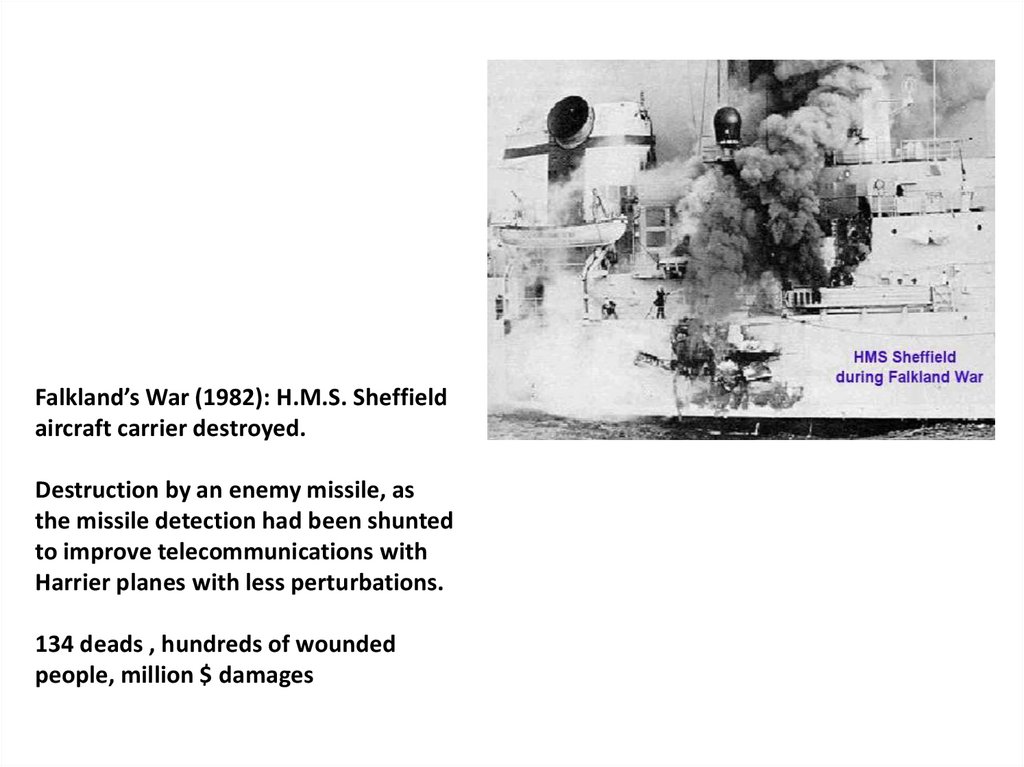
Falkland’s War (1982): H.M.S. Sheffieldaircraft carrier destroyed.
Destruction by an enemy missile, as
the missile detection had been shunted
to improve telecommunications with
Harrier planes with less perturbations.
134 deads , hundreds of wounded
people, million $ damages
7.
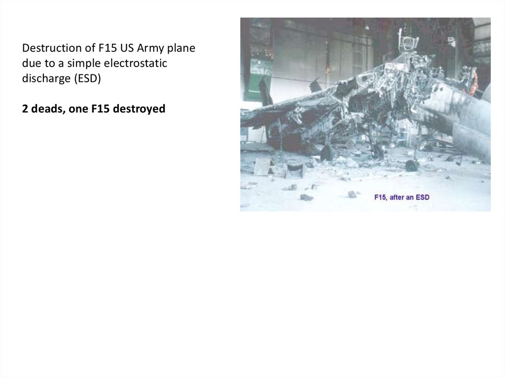
Destruction of F15 US Army planedue to a simple electrostatic
discharge (ESD)
2 deads, one F15 destroyed
8.
In late 80’s, CB (Citizen Band) transmitters of trucks, very powerful,re-set to zero benzin pump counters when they passed in emitting mode.
The first ABS (Antiblockiersystems) implemented on cars or trucks (1966)
were very sensitive to electromagnetic perturbations and caused many
accidents before manufacturers (Bosch) improved their specifications.
Parisian parking ticket machines were too sensitive to electrostatic
discharges. A simple cigarette lighter allowed to park the car without having
to pay the parking. Unfortunately, the problem is now solved.
9.
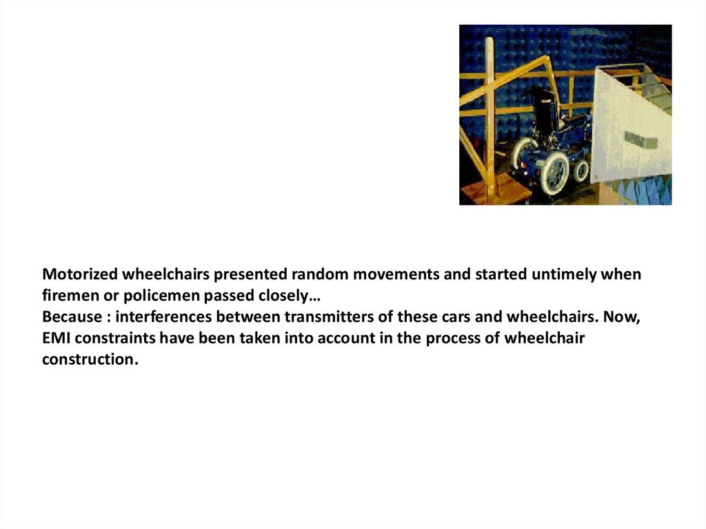
Motorized wheelchairs presented random movements and started untimely whenfiremen or policemen passed closely…
Because : interferences between transmitters of these cars and wheelchairs. Now,
EMI constraints have been taken into account in the process of wheelchair
construction.
10.
EMI problems are not new, because… (brief history)Since 1905: first observations: perturbations from electronic devices can affect
radio communications -> notions of parasite and antiparasite
1900 -> 1920: More and more electric machines in industrial landscape:
-> problems with electric supply
-> problems with security of people: workers, customers, …
-> including lightning protection
In 1906 : Creation of International Electrotechnical Commission (IEC), positioned
in Geneve since 1948, gathering 69 countries, complementary to ISO (International
system Organisation). ISO and IEC define norms in all engineering domains.
In 1933: Meeting of IEC in Paris : It was decided to establish norms, rules at
international level. Need to protect radio communications.
Interest of norms:
- To facilitate exchanges in the whole world in deleting technical jumps,
- To assure products quality,
- To warrant products and systems interoperability,
- To improve the security when using products,
- To help preserving energetic efficiency and ecologic reducting of chemical
rejects (life quality).
11.
1934 : Creation of ISCRI (International Special Committee on Radio Interference)to establish limits, attempts proccesses and recommendations in specific cases of
radiocommunications.
1945 : American army defined emission requirements for their equipments (JAN-I-225).
1950 : First requirement insensitivity, still for American military materials (MIL- I -6181)
From 1960 : Frequent new norms EMI in military devices. Recommendations and norms in
car manufactoties and light industry. Due to fast transistor development, it became evident
that electrical devices missed protections against electromagnetic perturbations.
Development of electronic devices with a great slope in house, specificaly in phones,
domestic electrical appliances, then computers, cellular phones, …
1989 : European Directive 89/336 CE to enhance international trading exchanges and to
propose a good managing of electromagnetic environment
1992 : Translation in French laws of European Directive 89/336 CE and transient time until
December 31 1995 for all French companies to become in accordance with this directive.
1993 : CE marks. Integration of telecommunication in directive EMI.
1996 : CE mark became obligatory in all electrical, electrotechnical and electronic devices.
12.
ELECTROMAGNETIC INTERFERENCES (EMI) :It is the aptitude of an equipment (or a
system) to behave correctly in its
electromagnetic environment (sensitivity
side ) and without produce itself
electromagnetic perturbations which can
cause bad behaviour for its neighbouring
devices (emission side).
(international electrical vocabulary)
13.
Note that, in French, it is called Compatibilité électromagnétiquewhich includes all points of view.
In English, electromagnetic interferences is the general speciality,
englobing electromagnetic compatibility, which only concerns
the equipement qualities.
Two types of problems can occur:
Our system is guilty: it produces perturbations (emission point of view)
Our system is victim: it submits perturbations (sensitivity point of view)
Two propagation modes exist:
Radiative mode (by waves)
Driven mode (by wires or cables)
We have to consider 4 cases:
14.
SusceptibilityEmission
Radiated
perturbations
RS
RE
Driven
perturbations
DS
DE
Also, between victims and guilty devices, there exist 6 different modes of
coupling, unfortunately acting often together
-Coupling by common impedances
-Coupling between plans and conductors
-Electrical field on conductor
-Magnetic field on loop
-Electrical crosstalk (electrical diaphony)
-Magnetic crosstalk (magnetic diaphony)
15.
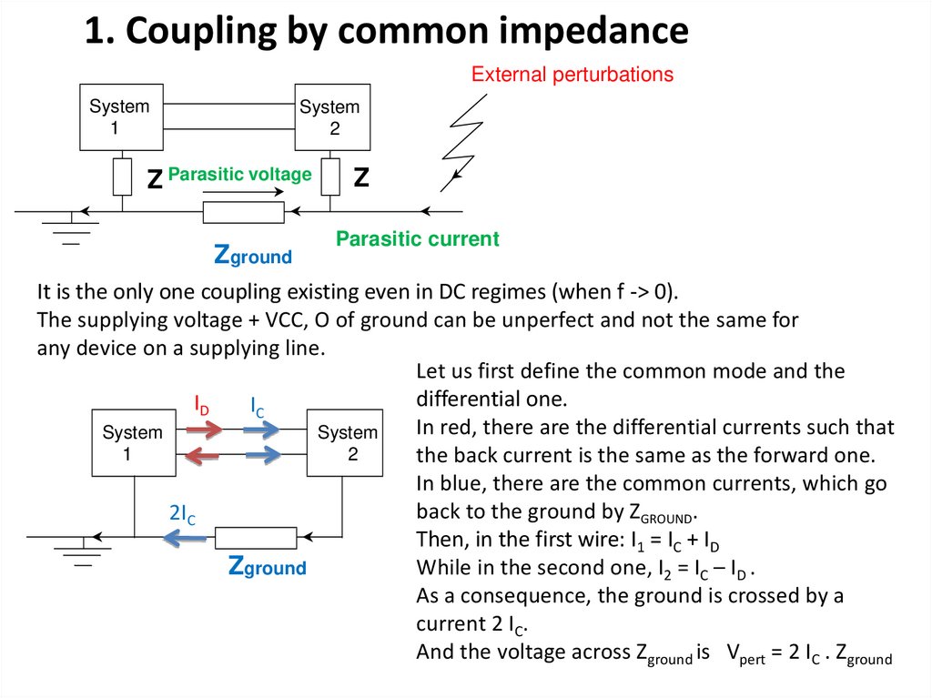
1. Coupling by common impedanceExternal perturbations
System
1
System
2
Z Parasitic voltage
Zground
Z
Parasitic current
It is the only one coupling existing even in DC regimes (when f -> 0).
The supplying voltage + VCC, O of ground can be unperfect and not the same for
any device on a supplying line.
Let us first define the common mode and the
differential one.
ID
IC
In red, there are the differential currents such that
System
System
1
2
the back current is the same as the forward one.
In blue, there are the common currents, which go
back to the ground by ZGROUND.
2IC
Then, in the first wire: I1 = IC + ID
While in the second one, I2 = IC – ID .
Zground
As a consequence, the ground is crossed by a
current 2 IC.
And the voltage across Zground is Vpert = 2 IC . Zground
16.
In a general rule, the good mode to transmit informations is the differentialmode, the one allowing that eventual defects, as temperature deviations or
ageing of electrical components, compensate themselfes.
The common mode is a bad mode, focusing all the problems of perturbations
and it is often the worst enemy of EMI specialists.
Remember about the common mode rejection ratio for differential amplifiers
(Ideal operational amplifiers) where it is common to have more than 80 dB of
rejection CM with respect of DM.
Here, to reduce the coupling by common impedance, it is required to decrease
the ground impedance with short and large wires , and minimize the possibility
of any current through the grounds of the different devices. It is also advised to
use metallic braids to rely the device frames to the ground.
17.
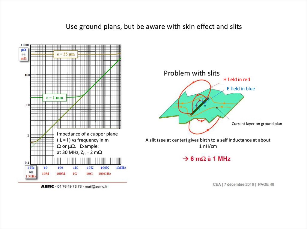
Use ground plans, but be aware with skin effect and slitsProblem with slits
H field in red
E field in blue
Current layer on ground plan
Impedance of a cupper plane
( L = l ) vs frequency in m
or . Example:
at 30 MHz, Z = 2 m
A slit (see at center) gives birth to a self inductance at about
1 nH/cm
18.
Correctly choose the conductor shapes, be aware of inductance effectsCupper conductors L = 1 m
Reactive (inductive part)
With L length in m
S section in mm2
Resistive part
At cut-off frequency, the resistive part (R) and the reactive one (L ) are equal
19.
System1
Z
System
2
Parasitic
voltage
Zgnd
External perturbations
Z
parasitic current
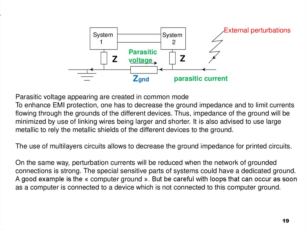
Parasitic voltage appearing are created in common mode
To enhance EMI protection, one has to decrease the ground impedance and to limit currents
flowing through the grounds of the different devices. Thus, impedance of the ground will be
minimized by use of linking wires being larger and shorter. It is also advised to use large
metallic to rely the metallic shields of the different devices to the ground.
The use of multilayers circuits allows to decrease the ground impedance for printed circuits.
On the same way, perturbation currents will be reduced when the network of grounded
connections is strong. The special sensitive parts of systems could have a dedicated ground.
A good example is the « computer ground ». But be careful with loops that can occur as soon
as a computer is connected to a device which is not connected to this computer ground.
19
20.
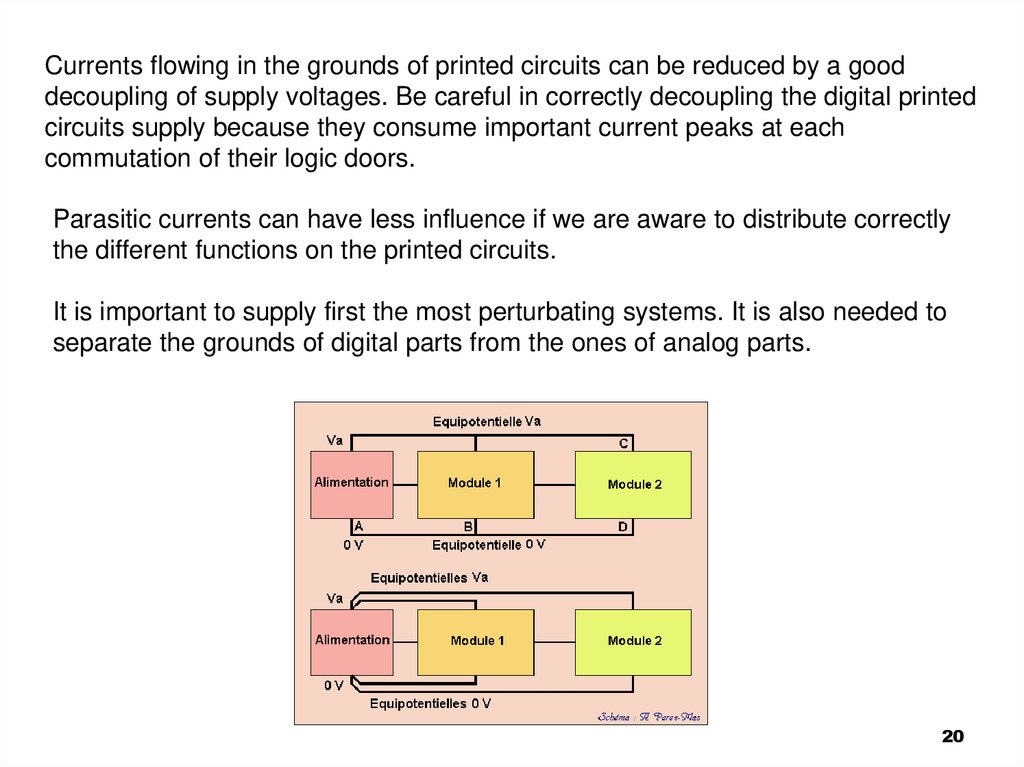
Currents flowing in the grounds of printed circuits can be reduced by a gooddecoupling of supply voltages. Be careful in correctly decoupling the digital printed
circuits supply because they consume important current peaks at each
commutation of their logic doors.
Parasitic currents can have less influence if we are aware to distribute correctly
the different functions on the printed circuits.
It is important to supply first the most perturbating systems. It is also needed to
separate the grounds of digital parts from the ones of analog parts.
20
21.
Exercises:1) For vehicles, sensors, systems, … are often supplied with 12 V DC, through a
single wire coming from the + pole of the battery. How does the return back of the
current to the – pole of the battery ? Explain why such an energy supply is very
bad for EMI reasons.
2) Two formulas allow to determine the impedance of a cupper square plane (see
document 2). At low frequencies, R ( in /carré) = 16 / e, where e is the thickness
of the square in mm. Why the other dimensions of the square do not influence it?
At high frequencies, Z (in /carré) = 125√F(MHz). Why does the frequency play a
role with a square root ? Correct the mistake on the graph…
21
22.
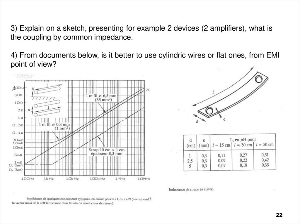
3) Explain on a sketch, presenting for example 2 devices (2 amplifiers), what isthe coupling by common impedance.
4) From documents below, is it better to use cylindric wires or flat ones, from EMI
point of view?
22
23.
5) Why is it necessary to mesh as much as possible the ground connections of the differensystems in industrial buildings?
To avoid perturbations by common impedance in distribution circuits, the grounding
network must be, at the maximum, equipotential, then linked to earth protection.
C
G
A
Zi
B
D
H
ZAB = ?, ZGH = ?, ZCD = ?
Volume connection of ground , by a strong cabling, as squashed as
possible, to become close to a Faraday’s cage
23
24.
6) In an office building, a small computer and its printer are in the same room, withtheir electrical supply on wall sockets (power points) A and B, distant from 5 meters.
At the same level, on the same electrical line from electrical board, a cooling device
has been put in place.
At each time the air-conditioner switchs commutations from working/stop states, the
compressor motor leads to the earth protection cable a transient current of 4
amperespeak to peak, with oscillation at about 200 kHz. What is then the voltage
difference between A and B at these times? Compare this value to the typical noise
margin for numerical circuits. Conclude and propose some precautions to take.
7) On a single layer card, distribution of voltages and grounds is made by straps with
1 mm wide. One of the integred boxes has 5 HCMOS doors synchronized with the
clock. At each logic commutations, transient current is 10 mA by door , with a rising
time of 4 ns. If no precautionis taken into account, what is the parasitic voltage on a
path 0 V (width 1 mm, length 10 cm ) when the current goes back to the voltage
supply ( VCC= + 5 V).
24
25.
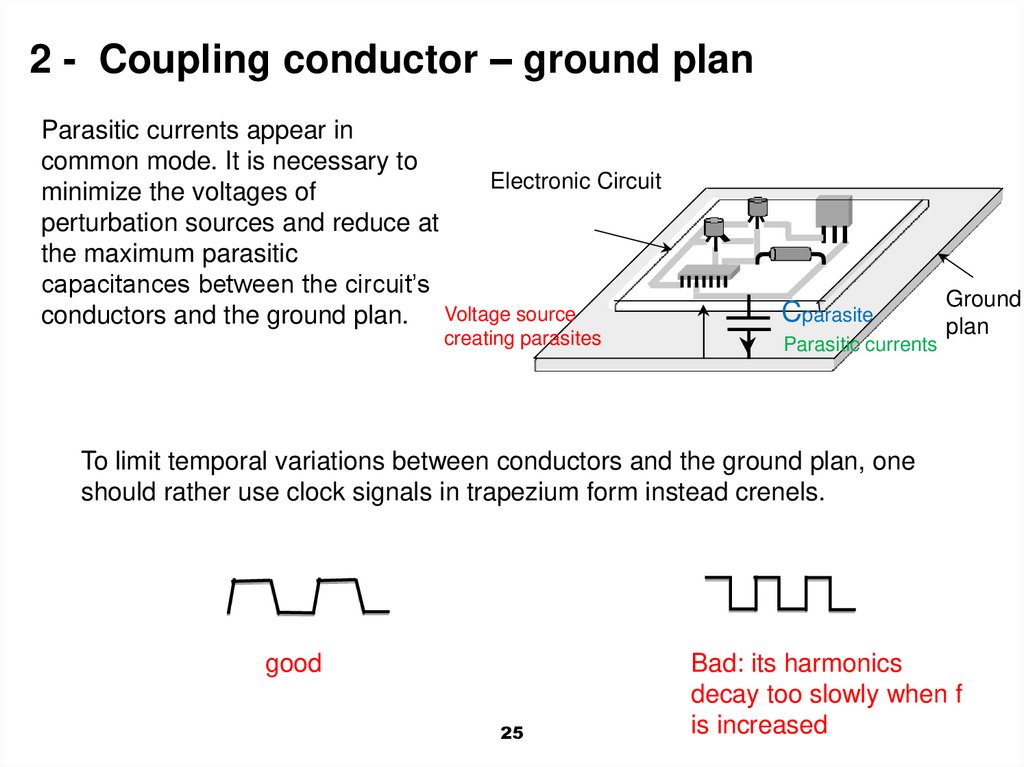
2 - Coupling conductor – ground planParasitic currents appear in
common mode. It is necessary to
Electronic Circuit
minimize the voltages of
perturbation sources and reduce at
the maximum parasitic
capacitances between the circuit’s
conductors and the ground plan. Voltage source
creating parasites
Cparasite
Parasitic currents
Ground
plan
To limit temporal variations between conductors and the ground plan, one
should rather use clock signals in trapezium form instead crenels.
good
25
Bad: its harmonics
decay too slowly when f
is increased
26.
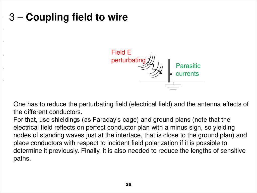
3 – Coupling field to wireField E
perturbating
Parasitic
currents
One has to reduce the perturbating field (electrical field) and the antenna effects of
the different conductors.
For that, use shieldings (as Faraday’s cage) and ground plans (note that the
electrical field reflects on perfect conductor plan with a minus sign, so yielding
nodes of standing waves just at the interface, that is close to the ground plan) and
place conductors with respect to incident field polarization if it is possible to
determine it previously. Finally, it is also needed to reduce the lengths of sensitive
paths.
26
27.
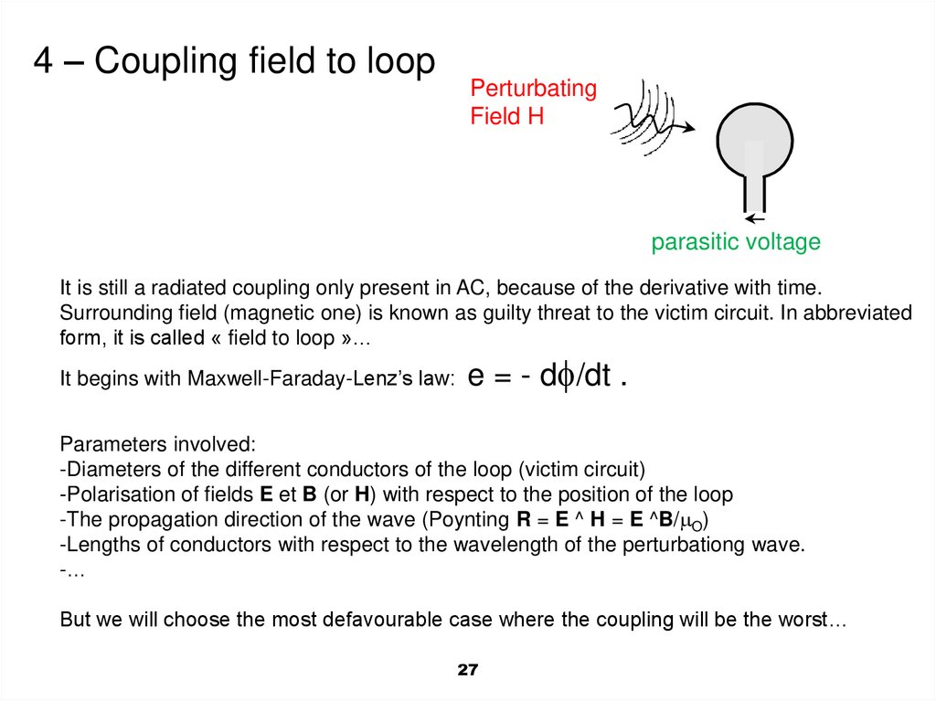
4 – Coupling field to loopPerturbating
Field H
parasitic voltage
It is still a radiated coupling only present in AC, because of the derivative with time.
Surrounding field (magnetic one) is known as guilty threat to the victim circuit. In abbreviated
form, it is called « field to loop »…
It begins with Maxwell-Faraday-Lenz’s law:
e = - d /dt .
Parameters involved:
-Diameters of the different conductors of the loop (victim circuit)
-Polarisation of fields E et B (or H) with respect to the position of the loop
-The propagation direction of the wave (Poynting R = E ^ H = E ^B/ O)
-Lengths of conductors with respect to the wavelength of the perturbationg wave.
-…
But we will choose the most defavourable case where the coupling will be the worst…
27
28.
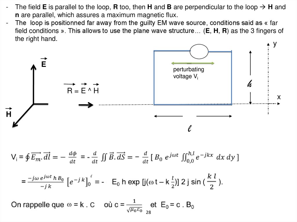
-The field E is parallel to the loop, R too, then H and B are perpendicular to the loop H and
n are parallel, which assures a maximum magnetic flux.
The loop is positionned far away from the guilty EM wave source, conditions said as « far
field conditions ». This allows to use the plane wave structure… (E, H, R) as the 3 fingers of
the right hand.
y
E
perturbating
voltage Vi
R=E^H
h
x
H
l
28
29.
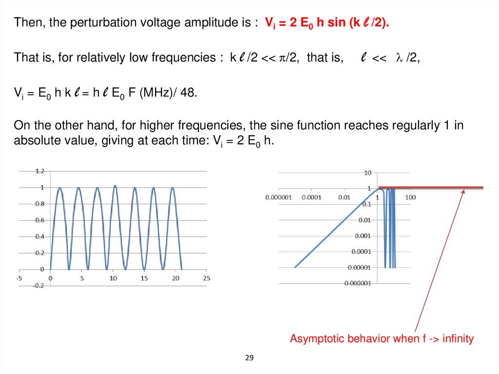
Then, the perturbation voltage amplitude is : Vi = 2 E0 h sin (k l /2).That is, for relatively low frequencies : k l /2 << /2, that is,
l
<< /2,
Vi = E0 h k l = h l E0 F (MHz)/ 48.
On the other hand, for higher frequencies, the sine function reaches regularly 1 in
absolute value, giving at each time: Vi = 2 E0 h.
Asymptotic behavior when f -> infinity
29
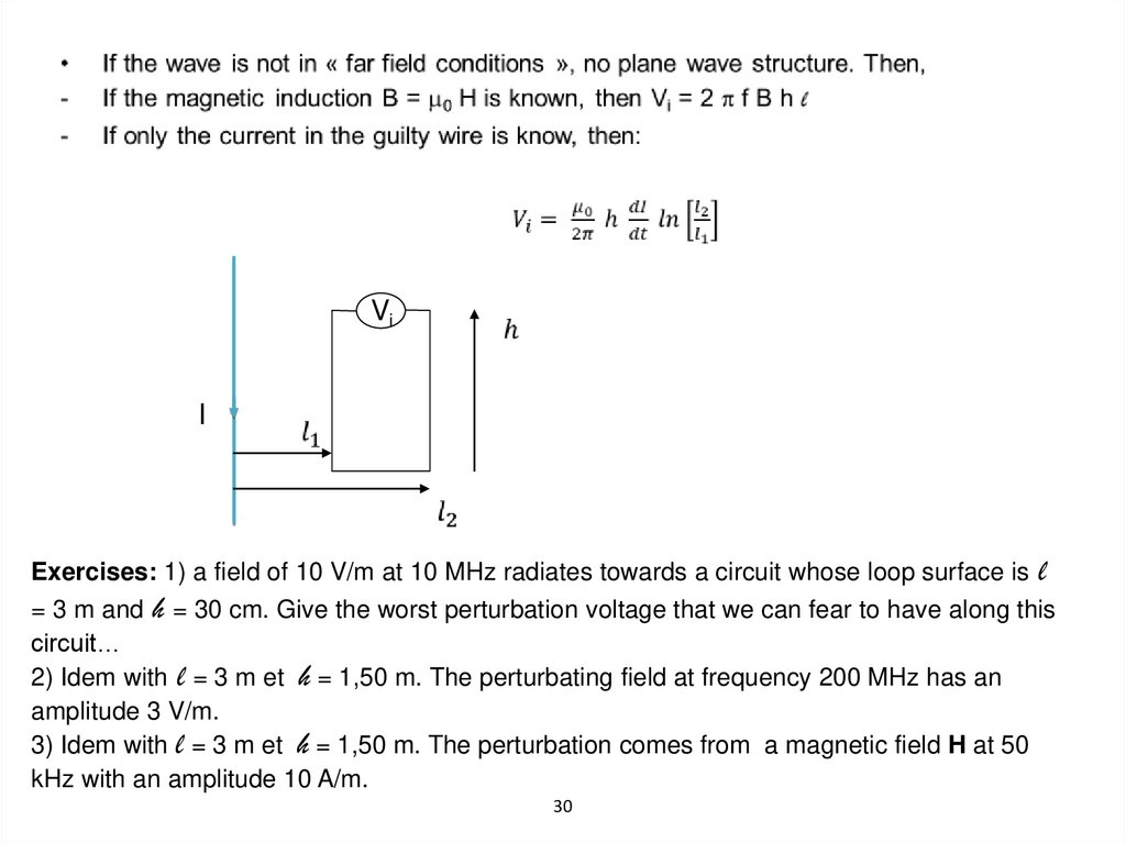
30.
ViI
Exercises: 1) a field of 10 V/m at 10 MHz radiates towards a circuit whose loop surface is
l
= 3 m and h = 30 cm. Give the worst perturbation voltage that we can fear to have along this
circuit…
2) Idem with l = 3 m et h = 1,50 m. The perturbating field at frequency 200 MHz has an
amplitude 3 V/m.
3) Idem with l = 3 m et h = 1,50 m. The perturbation comes from a magnetic field H at 50
kHz with an amplitude 10 A/m.
30
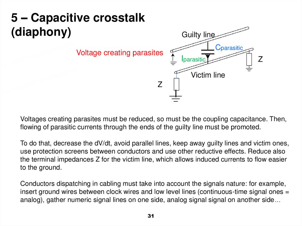
31.
5 – Capacitive crosstalk(diaphony)
Guilty line
Voltage creating parasites
Cparasitic
Iparasitic
Z
Victim line
Z
Voltages creating parasites must be reduced, so must be the coupling capacitance. Then,
flowing of parasitic currents through the ends of the guilty line must be promoted.
To do that, decrease the dV/dt, avoid parallel lines, keep away guilty lines and victim ones,
use protection screens between conductors and use other reductive effects. Reduce also
the terminal impedances Z for the victim line, which allows induced currents to flow easier
to the ground.
Conductors dispatching in cabling must take into account the signals nature: for example,
insert ground wires between clock wires and low level lines (continuous-time signal ones =
analog), gather numeric signal lines on one side, analog signal signal on another side…
31
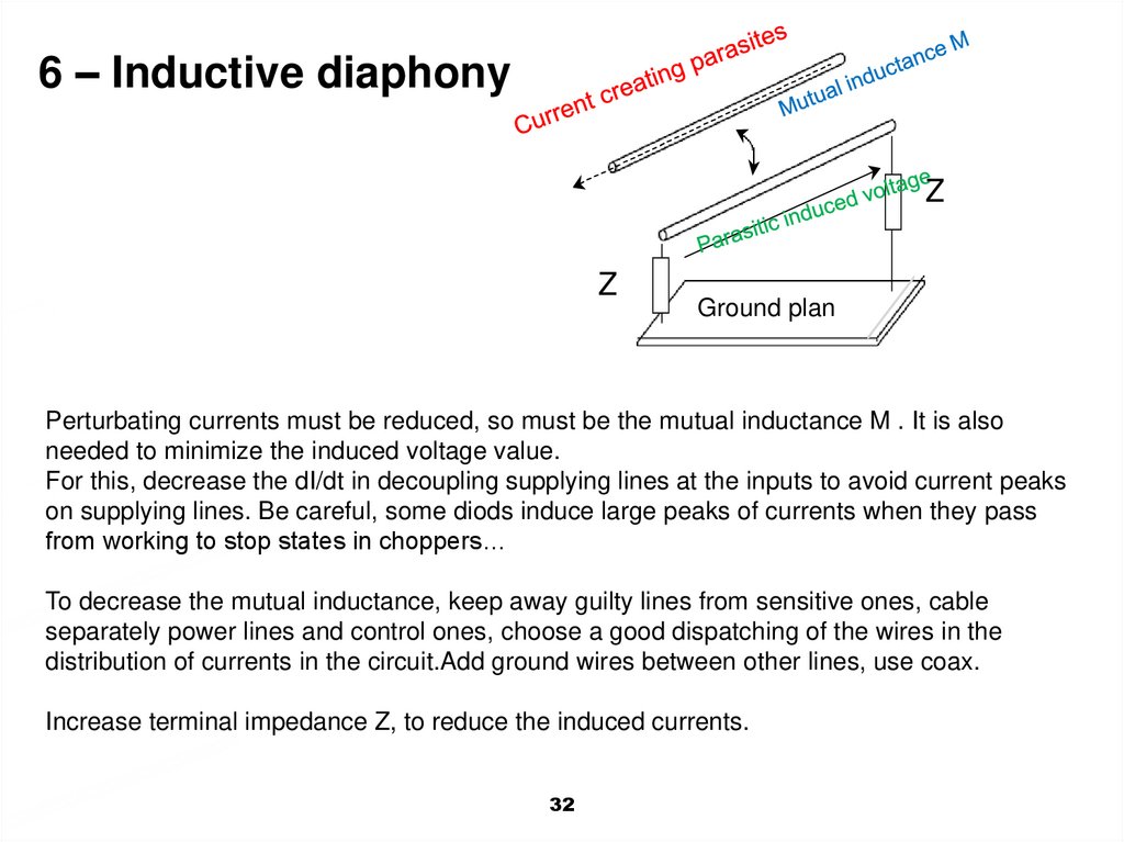
32.
6 – Inductive diaphonyZ
Z
Ground plan
Perturbating currents must be reduced, so must be the mutual inductance M . It is also
needed to minimize the induced voltage value.
For this, decrease the dI/dt in decoupling supplying lines at the inputs to avoid current peaks
on supplying lines. Be careful, some diods induce large peaks of currents when they pass
from working to stop states in choppers…
To decrease the mutual inductance, keep away guilty lines from sensitive ones, cable
separately power lines and control ones, choose a good dispatching of the wires in the
distribution of currents in the circuit.Add ground wires between other lines, use coax.
Increase terminal impedance Z, to reduce the induced currents.
32
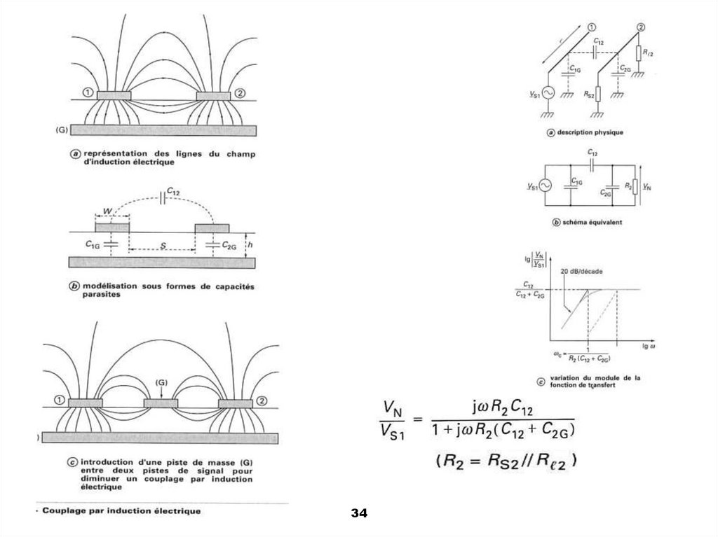
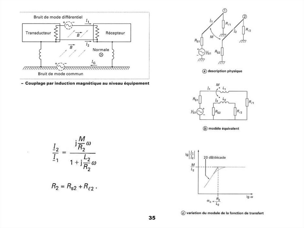
33.
Exercise: in comparing the coupling modes: diaphony by capacitiveeffects and diaphony by inductive effects, the advices seem to be
contradictory… To reduce the capacitive diaphony, one has to decrease
the terminal impedances (input and output) of the victim line. To reduce
the inductance diaphony, one has to increase these terminal impedances
of the victim line. Explain that with simple sketchs and show why it is
possible to perform both recommendations.
33
34.
3435.
3536.
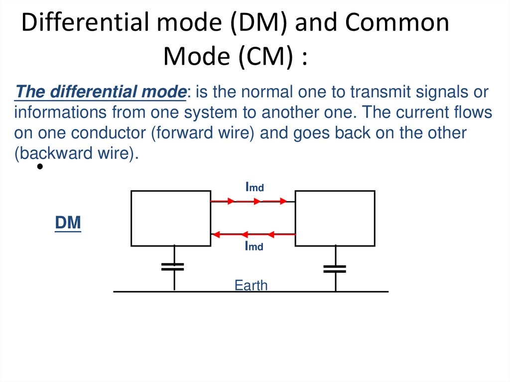
Differential mode (DM) and CommonMode (CM) :
The differential mode: is the normal one to transmit signals or
informations from one system to another one. The current flows
on one conductor (forward wire) and goes back on the other
(backward wire).
Imd
DM
Imd
Earth
37.
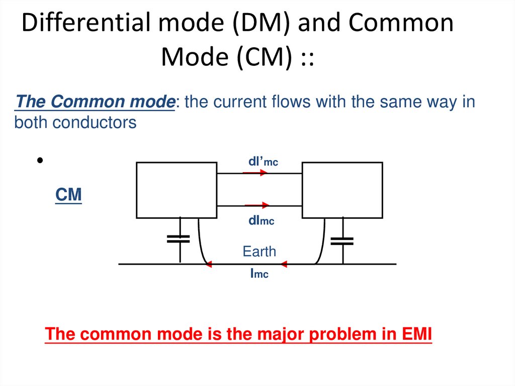
Differential mode (DM) and CommonMode (CM) ::
The Common mode: the current flows with the same way in
both conductors
dI’mc
CM
dImc
Earth
Imc
The common mode is the major problem in EMI
38.
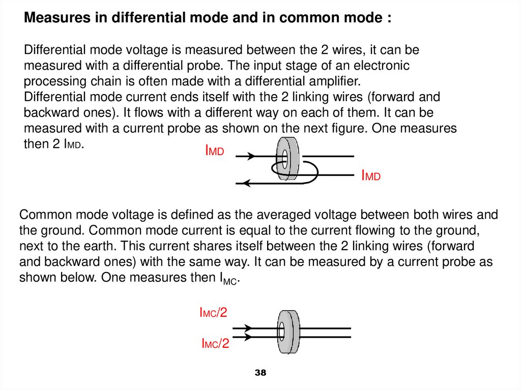
Measures in differential mode and in common mode :Differential mode voltage is measured between the 2 wires, it can be
measured with a differential probe. The input stage of an electronic
processing chain is often made with a differential amplifier.
Differential mode current ends itself with the 2 linking wires (forward and
backward ones). It flows with a different way on each of them. It can be
measured with a current probe as shown on the next figure. One measures
then 2 IMD.
IMD
IMD
Common mode voltage is defined as the averaged voltage between both wires and
the ground. Common mode current is equal to the current flowing to the ground,
next to the earth. This current shares itself between the 2 linking wires (forward
and backward ones) with the same way. It can be measured by a current probe as
shown below. One measures then IMC.
IMC/2
IMC/2
38
39.
Some solutions to prevent common mode propagationSolutions allow to avoid any mode propagation along the wires, either
in common mode or in differential mode:
In common mode, the ferrite surrounds the 2 conductors
In differential mode, the ferrite surrounds only one conductor, and a
second one surrounds the other conductor.
Protection by ferrites
39
40.
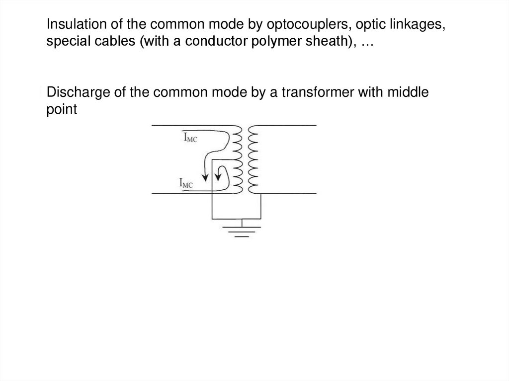
Insulation of the common mode by optocouplers, optic linkages,special cables (with a conductor polymer sheath), …
Discharge of the common mode by a transformer with middle
point
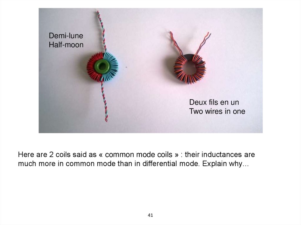
41.
Demi-luneHalf-moon
Deux fils en un
Two wires in one
Here are 2 coils said as « common mode coils » : their inductances are
much more in common mode than in differential mode. Explain why…
41
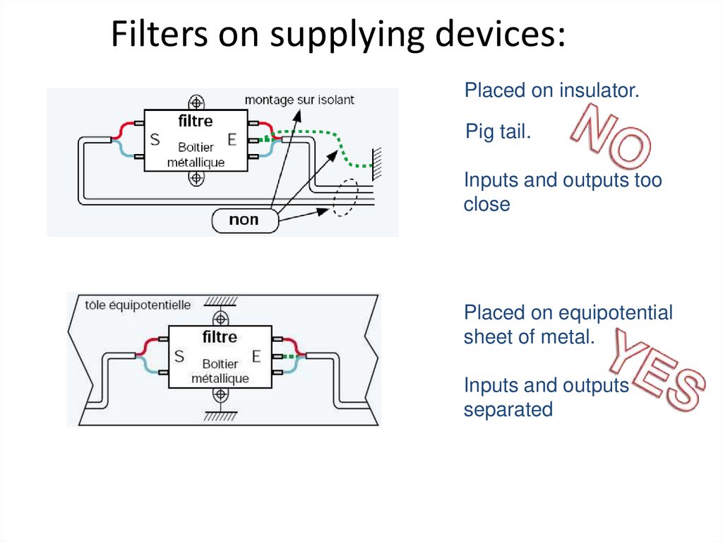
42.
Filters on supplying devices:Placed on insulator.
Pig tail.
Inputs and outputs too
close
Placed on equipotential
sheet of metal.
Inputs and outputs
separated