


 physics
Similar presentations:


")

")


")

Lecture 12 Current & Resistance
1.
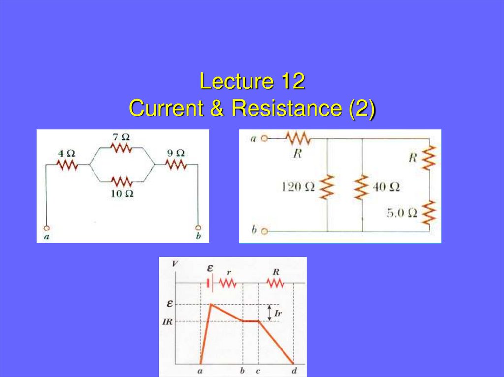
Lecture 12Current & Resistance (2)
2.
Temperature Variation of Resistance• The resistivity of a metal depends on many
(environmental) factors.
• The most important factor is the temperature.
• For most metals, the resistivity increases with increasing
temperature.
• The increased resistivity arises because of larger friction
caused by the more violent motion of the atoms of the
metal.
3.
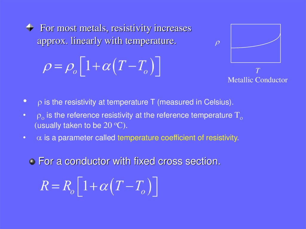
For most metals, resistivity increasesapprox. linearly with temperature.
r
T
Metallic Conductor
r is the resistivity at temperature T (measured in Celsius).
ro is the reference resistivity at the reference temperature To
(usually taken to be 20 oC).
• a is a parameter called temperature coefficient of resistivity.
For a conductor with fixed cross section.
4.
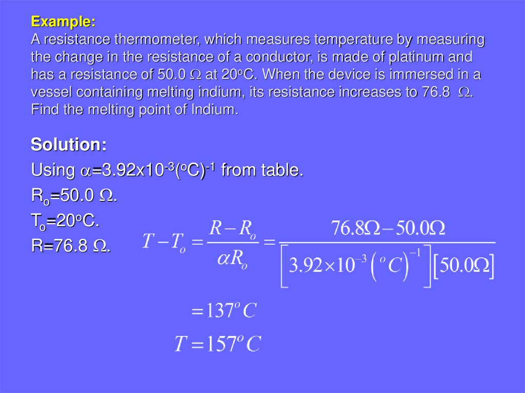
Example:A resistance thermometer, which measures temperature by measuring
the change in the resistance of a conductor, is made of platinum and
has a resistance of 50.0 W at 20oC. When the device is immersed in a
vessel containing melting indium, its resistance increases to 76.8 W.
Find the melting point of Indium.
Solution:
Using a=3.92x10⁻³(oC)-1 from table.
Ro=50.0 W.
To=20oC.
R=76.8 W.
5.
[Q] A resistance thermometer using a platinum wire is used to measurethe temperature of a liquid. The resistance is 2.42 ohms at 0oC, and
when immersed in the liquid it is 2.98 ohms. The temperature
coefficient of resistivity of platinum is 0.0038 . What is the
temperature of the liquid?
6.
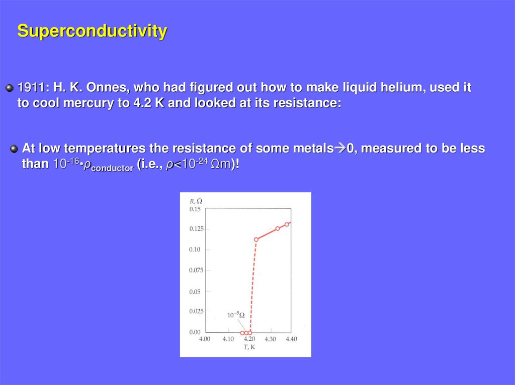
Superconductivity1911: H. K. Onnes, who had figured out how to make liquid helium, used it
to cool mercury to 4.2 K and looked at its resistance:
At low temperatures the resistance of some metals 0, measured to be less
than 10-16•ρconductor (i.e., ρ<10-24 Ωm)!
7.
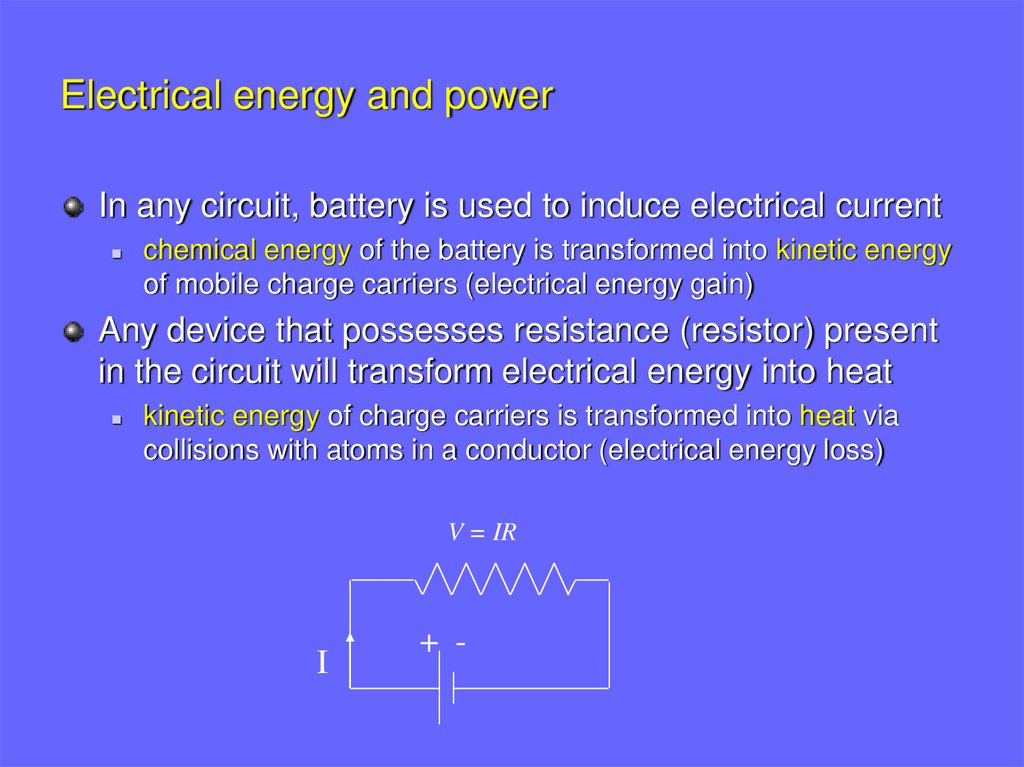
Electrical energy and powerIn any circuit, battery is used to induce electrical current
chemical energy of the battery is transformed into kinetic energy
of mobile charge carriers (electrical energy gain)
Any device that possesses resistance (resistor) present
in the circuit will transform electrical energy into heat
kinetic energy of charge carriers is transformed into heat via
collisions with atoms in a conductor (electrical energy loss)
V = IR
I
+ -
8.
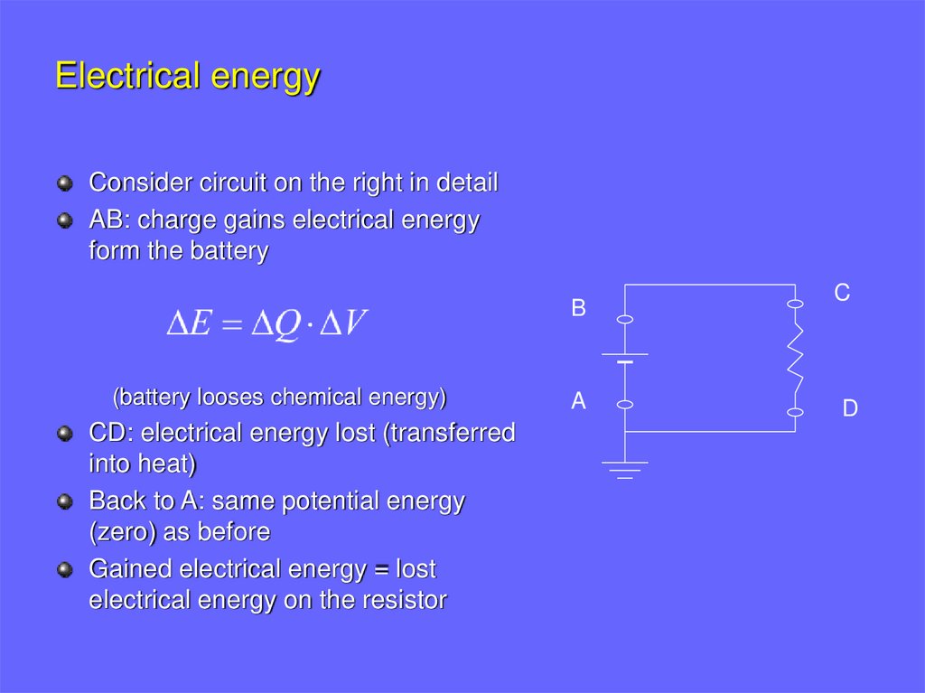
Electrical energyConsider circuit on the right in detail
AB: charge gains electrical energy
form the battery
B
(battery looses chemical energy)
CD: electrical energy lost (transferred
into heat)
Back to A: same potential energy
(zero) as before
Gained electrical energy = lost
electrical energy on the resistor
A
C
D
9.
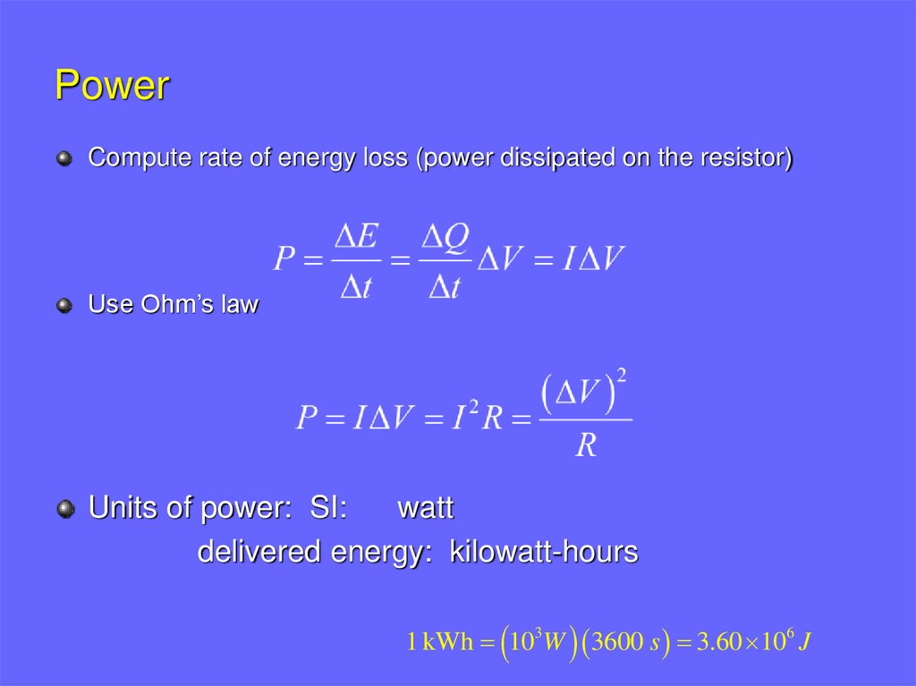
PowerCompute rate of energy loss (power dissipated on the resistor)
Use Ohm’s law
Units of power: SI:
watt
delivered energy: kilowatt-hours
1 kWh 103W 3600 s 3.60 106 J
10.
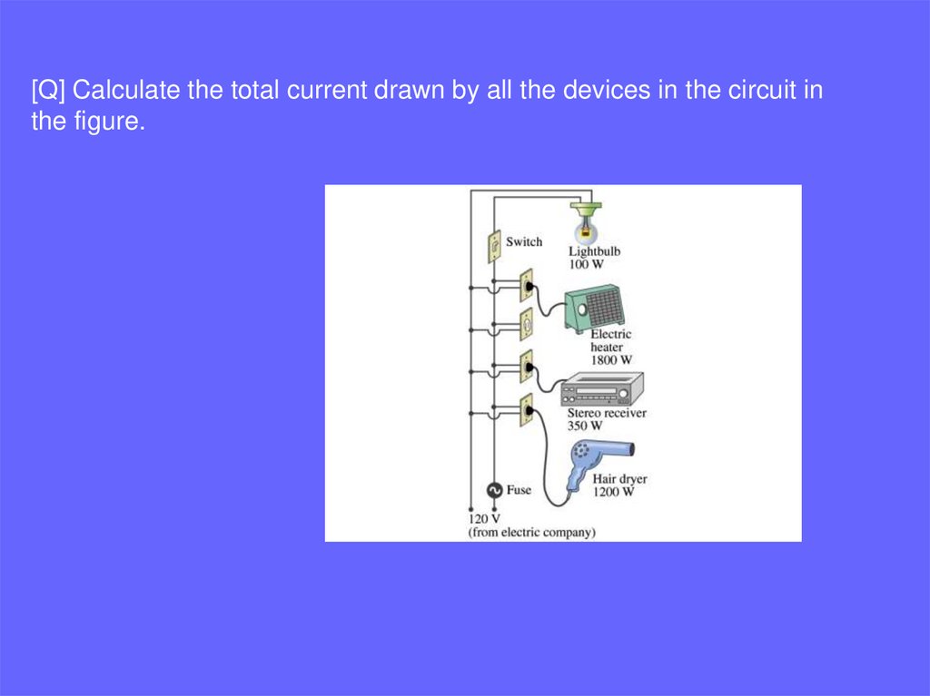
[Q] Calculate the total current drawn by all the devices in the circuit inthe figure.
11.
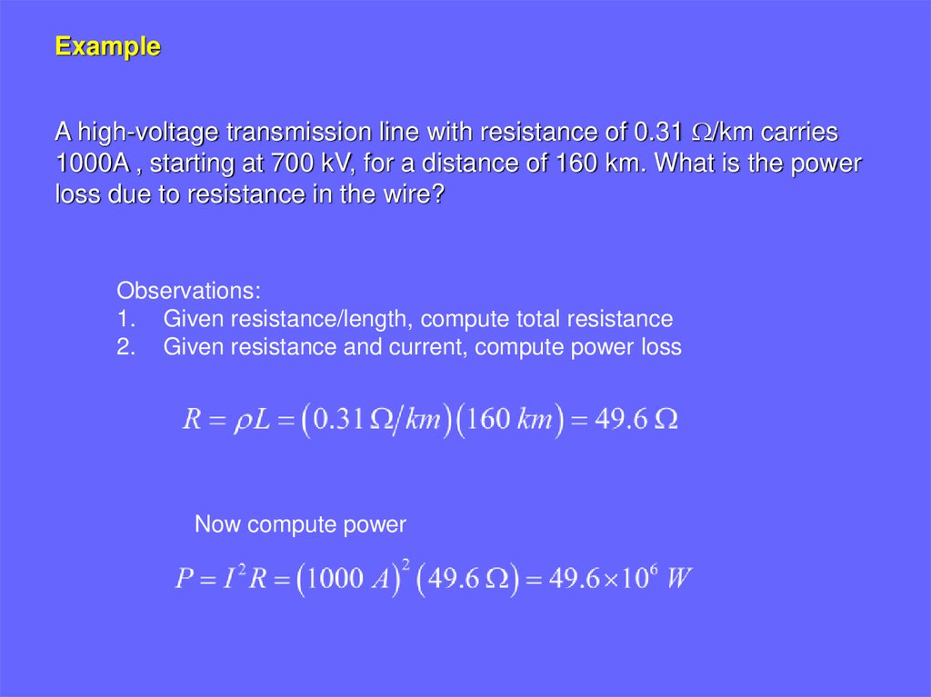
ExampleA high-voltage transmission line with resistance of 0.31 W/km carries
1000A , starting at 700 kV, for a distance of 160 km. What is the power
loss due to resistance in the wire?
Observations:
1. Given resistance/length, compute total resistance
2. Given resistance and current, compute power loss
Now compute power
12.
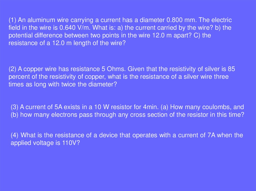
(1) An aluminum wire carrying a current has a diameter 0.800 mm. The electricfield in the wire is 0.640 V/m. What is: a) the current carried by the wire? b) the
potential difference between two points in the wire 12.0 m apart? C) the
resistance of a 12.0 m length of the wire?
(2) A copper wire has resistance 5 Ohms. Given that the resistivity of silver is 85
percent of the resistivity of copper, what is the resistance of a silver wire three
times as long with twice the diameter?
(3) A current of 5A exists in a 10 W resistor for 4min. (a) How many coulombs, and
(b) how many electrons pass through any cross section of the resistor in this time?
(4) What is the resistance of a device that operates with a current of 7A when the
applied voltage is 110V?
13.
(5) Thermal energy is developed in a resistor at a rate of 100W when thecurrent is 3.0A. What is the resistance in ohms?
(6) A 1250W radiant heater is constructed to operate at 115V. (a) What will be
the current in the heater? (b) What is the resistance of the heating coil?
14.
What is emf?• A current is maintained in a closed circuit by a source of emf.
The term emf was originally an abbreviation for electromotive force
but emf is NOT really a force, so the long term is discouraged.
• A source of emf works as “charge pump” that forces electrons to move in
a direction opposite the electrostatic field inside the source.
Examples of such sources are:
batteries
generators
thermocouples
photo-voltaic cells
15.
16.
Each real battery has someinternal resistance
AB: potential increases by on
the source of EMF, then
decreases by Ir (because of
the internal resistance)
Thus, terminal voltage on the
battery DV is
b
r
E
a
Note: EMF is the same as the
terminal voltage when the
current is zero (open circuit)
17.
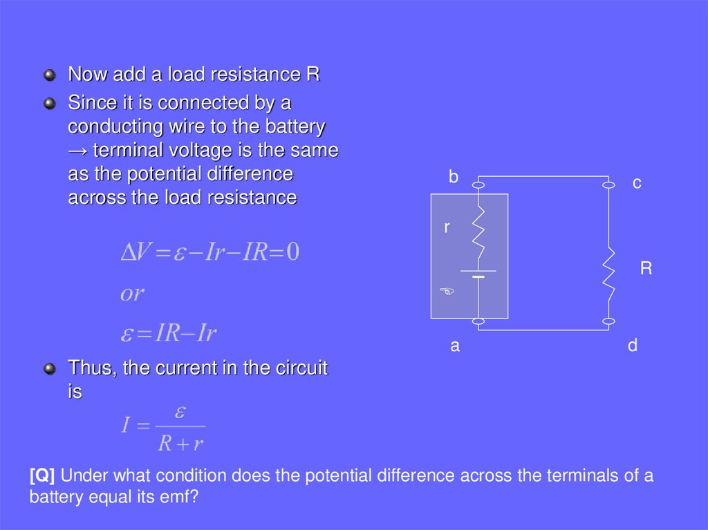
Now add a load resistance RSince it is connected by a
conducting wire to the battery
→ terminal voltage is the same
as the potential difference
across the load resistance
b
c
r
R
E
a
d
Thus, the current in the circuit
is
[Q] Under what condition does the potential difference across the terminals of a
battery equal its emf?
18.
Resistors in seriesA
+
v2 _
B
R2
+
v _
+
Ii1
R1
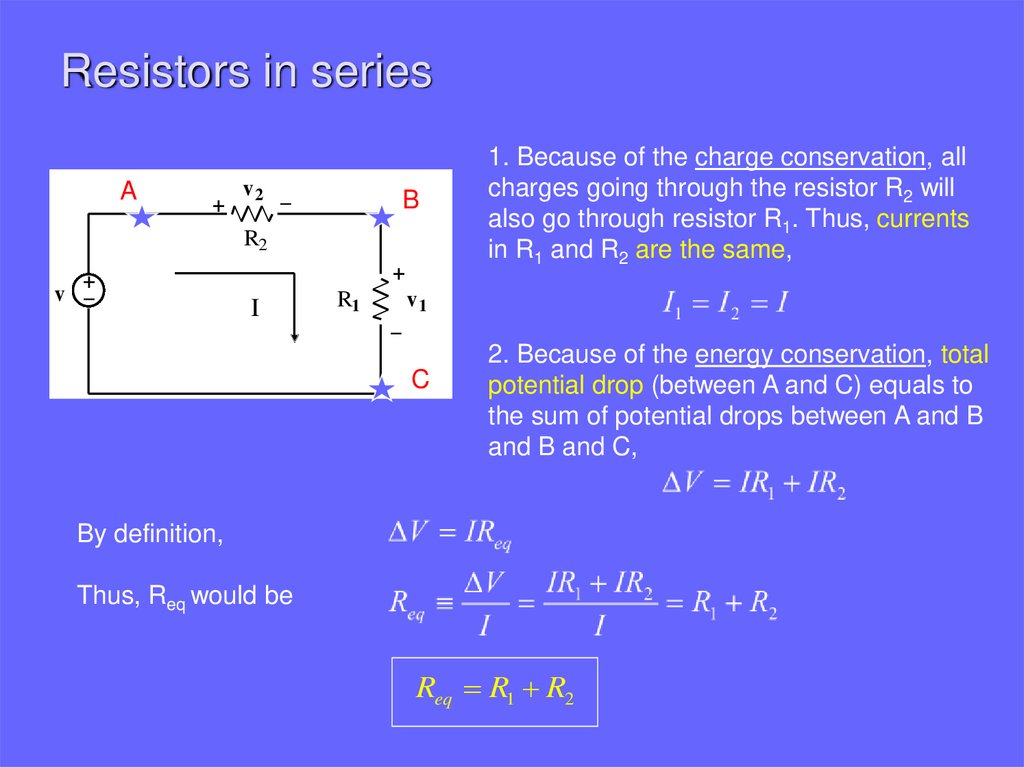
1. Because of the charge conservation, all
charges going through the resistor R2 will
also go through resistor R1. Thus, currents
in R1 and R2 are the same,
v1
_
C
2. Because of the energy conservation, total
potential drop (between A and C) equals to
the sum of potential drops between A and B
and B and C,
By definition,
Thus, Req would be
Req R1 R2
19.
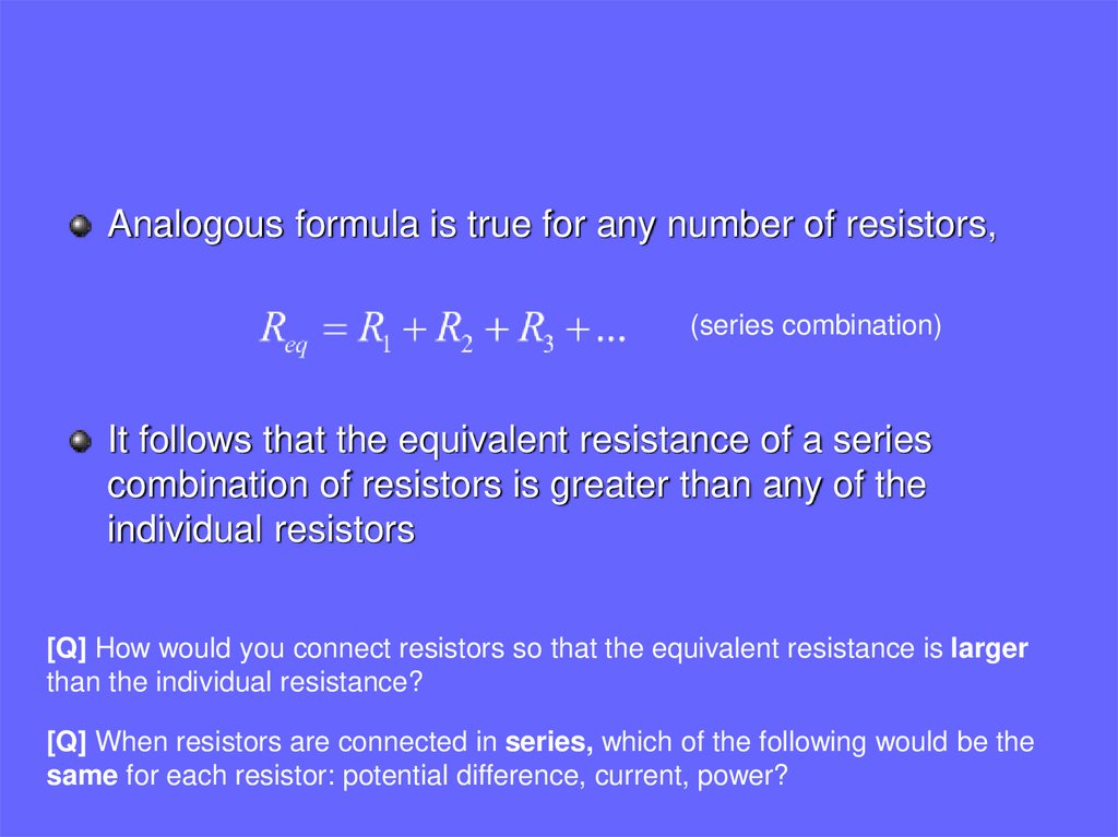
Analogous formula is true for any number of resistors,(series combination)
It follows that the equivalent resistance of a series
combination of resistors is greater than any of the
individual resistors
[Q] How would you connect resistors so that the equivalent resistance is larger
than the individual resistance?
[Q] When resistors are connected in series, which of the following would be the
same for each resistor: potential difference, current, power?
20.
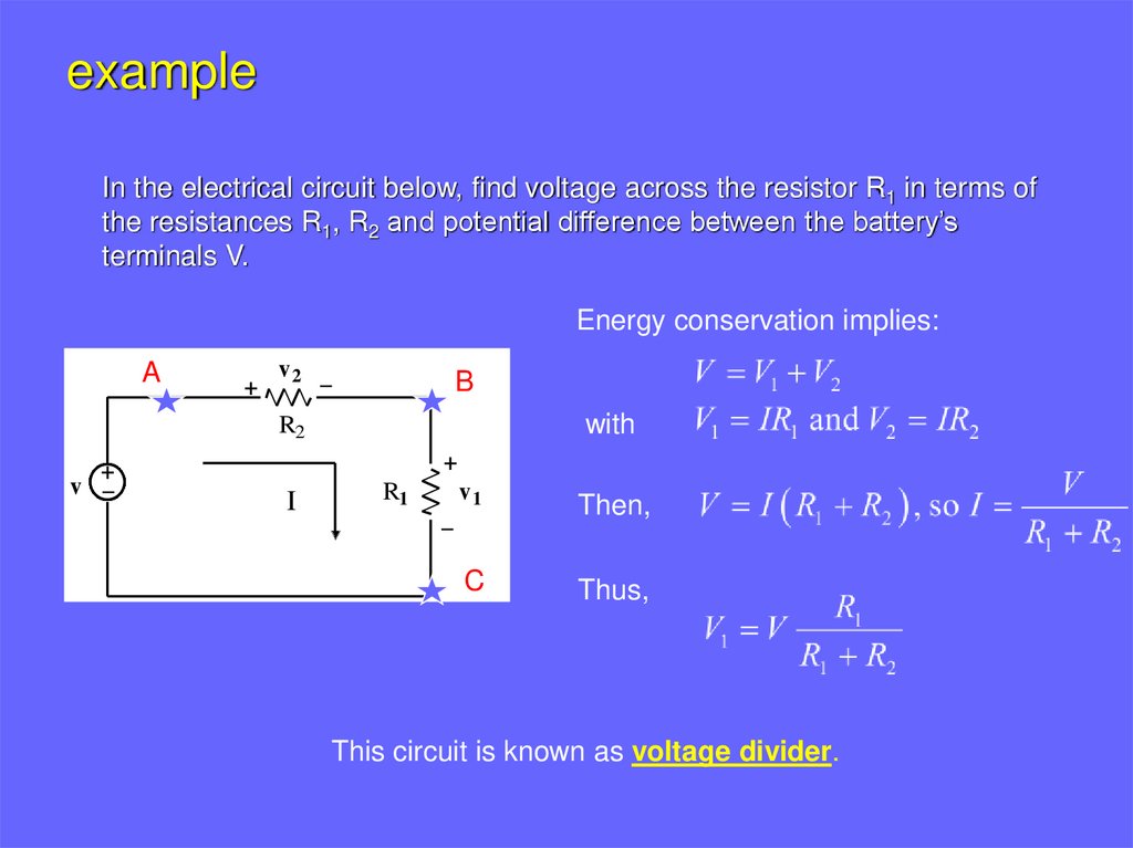
exampleIn the electrical circuit below, find voltage across the resistor R1 in terms of
the resistances R1, R2 and potential difference between the battery’s
terminals V.
Energy conservation implies:
A
+
v2 _
B
with
R2
+
v _
+
Ii1
R1
v1
Then,
C
Thus,
_
This circuit is known as voltage divider.
21.
Resistors in parallelI
+
A
I
I2
I1
R2
R1
V
_
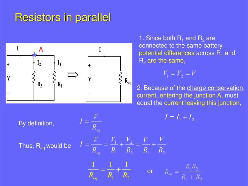
1. Since both R1 and R2 are
connected to the same battery,
potential differences across R1 and
R2 are the same,
+
V
Req
_
2. Because of the charge conservation,
current, entering the junction A, must
equal the current leaving this junction,
By definition,
Thus, Req would be
1
1
1
Req R1 R2
or
22.
Analogous formula is true for any number of resistors,(parallel combination)
It follows that the equivalent resistance of a parallel
combination of resistors is always less than any of the
individual resistors
[Q] How would you connect resistors so that the equivalent resistance is smaller than
the individual resistance?
[Q] When resistors are connected in parallel, which of the following would be the
same for each resistor: potential difference, current, power?
23.
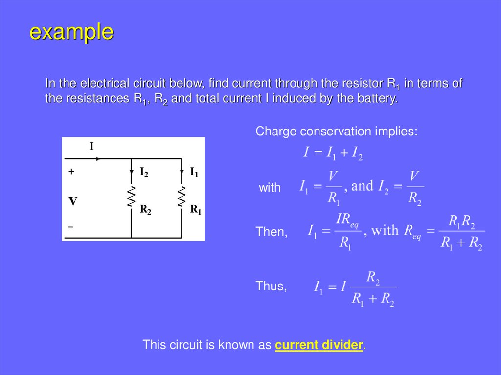
exampleIn the electrical circuit below, find current through the resistor R1 in terms of
the resistances R1, R2 and total current I induced by the battery.
Charge conservation implies:
I
+
I2
I1
with
V
_
R2
R1
Then,
Thus,
This circuit is known as current divider.
24.
(11) (a) Find the equivalent resistance between points a and b in Figure 8.27. (b)A potential difference of 34V is applied between points a and b in Figure 28.28.
Calculate the current in each resistor.
[Q] The resistance between terminals a and b in Figure is 75-ohms.
If the resistors labeled R have the same value, determine R.
25.
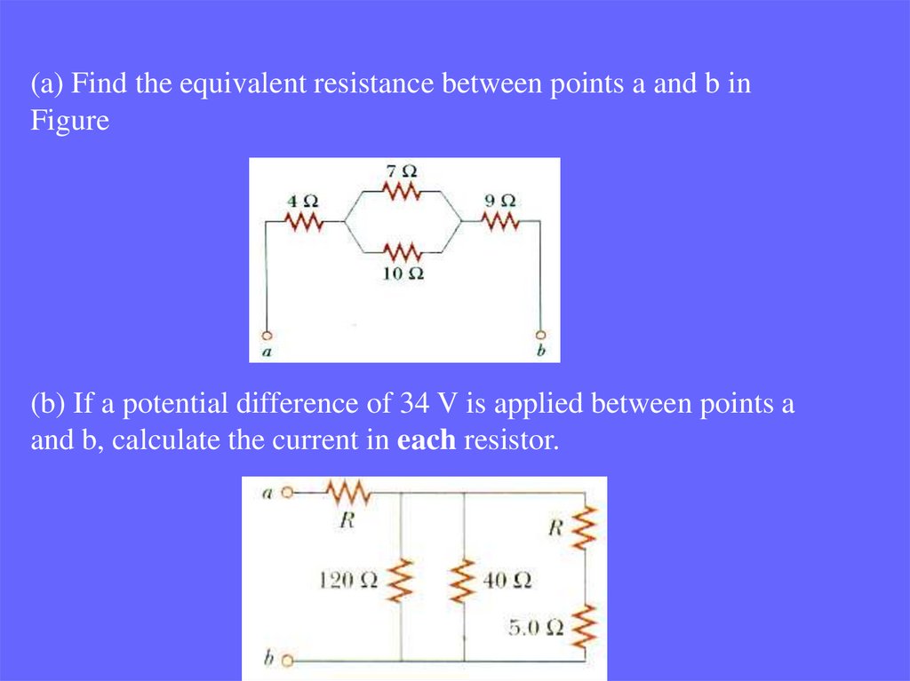
(a) Find the equivalent resistance between points a and b inFigure
(b) If a potential difference of 34 V is applied between points a
and b, calculate the current in each resistor.
26.
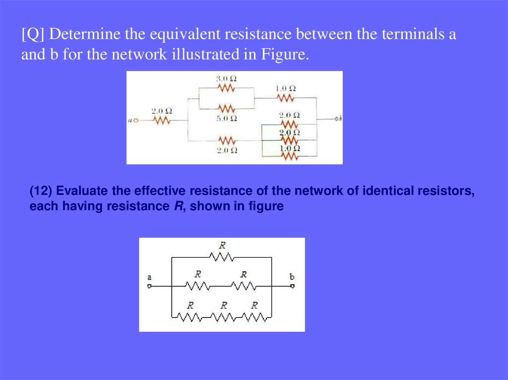
[Q] Determine the equivalent resistance between the terminals aand b for the network illustrated in Figure.
(12) Evaluate the effective resistance of the network of identical resistors,
each having resistance R, shown in figure
27.
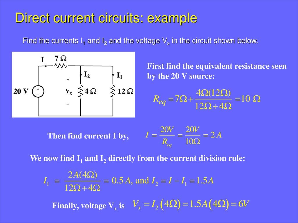
Direct current circuits: exampleFind the currents I1 and I2 and the voltage Vx in the circuit shown below.
I
7W
+
20 V
+
_
Vx
I2
I1
4W
12 W
_
Then find current I by,
First find the equivalent resistance seen
by the 20 V source:
4W(12W)
Req 7W
10 W
12W 4W
20V 20V
I
2A
Req
10W
We now find I1 and I2 directly from the current division rule:
I1
2 A(4W)
0.5 A, and I 2 I I1 1.5 A
12W 4W
Finally, voltage Vx is Vx I 2 4W 1.5 A 4W 6V
28.
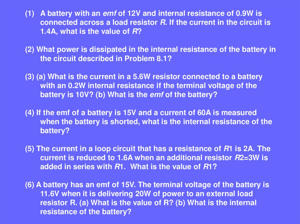
(1) A battery with an emf of 12V and internal resistance of 0.9W isconnected across a load resistor R. If the current in the circuit is
1.4A, what is the value of R?
(2) What power is dissipated in the internal resistance of the battery in
the circuit described in Problem 8.1?
(3) (a) What is the current in a 5.6W resistor connected to a battery
with an 0.2W internal resistance if the terminal voltage of the
battery is 10V? (b) What is the emf of the battery?
(4) If the emf of a battery is 15V and a current of 60A is measured
when the battery is shorted, what is the internal resistance of the
battery?
(5) The current in a loop circuit that has a resistance of R1 is 2A. The
current is reduced to 1.6A when an additional resistor R2=3W is
added in series with R1. What is the value of R1?
(6) A battery has an emf of 15V. The terminal voltage of the battery is
11.6V when it is delivering 20W of power to an external load
resistor R. (a) What is the value of R? (b) What is the internal
resistance of the battery?
29.
(7) A certain battery has an open-circuit voltage of 42V. A load resistance of12W reduces the terminal voltage to 35V. What is the value of the
internal resistance of the battery?
(8) Two circuit elements with fixed resistances R1 and R2 are connected in
series with a 6V battery and a switch. The battery has an internal resistance of
5W, R1= 32W, and R2=56W. (a) What is the current through R1 when the
switch is closed? (b) What is the voltage across R2 when the switch is closed?
(9) The current in a simple series circuit is 5.0A. When an additional resistance
of 2.0W is inserted, the current drops to 4.0 A. What was the resistance
of the original circuit?
(10) Three resistors (10W, 20W, and 30W) are connected in parallel. The
total current through this network is 5A. (a) What is the voltage drop
across the network (b) What is the current in each resistor?