


 industry
Similar presentations:


")


Apparatus of installations with fluidized layer of pulverized catalyst. Introduction
1. Apparatus of installations with fluidized layer of pulverized catalyst
Al-Farabi Kazakh national universityDepartment of physical chemistry,catalysis and petrochemistry
Apparatus of installations with fluidized layer
of pulverized catalyst
Performed by: Abdrassilova A.K.
Abik N.A.
Kurmangaliyeva A.B.
Otynshiyev Y.B.
Checked by Pavlenko V.V.
Almaty, 2019
2. Plan
• Introduction;• Main features of the process;
• Conclusion;
3.
Main features of the processThe advantages of this type of cracking compared to cracking, which
uses a ball catalyst, are:
- possibility of simple regulation within wide limits of degree of transformation
of raw materials and circulation of the catalyst;
- intensive mixing in the reactor and regenerator, eliminating local overheating
and providing high heat transfer coefficients;
- lower energy costs for catalyst transport;
- simpler designs of the main devices.
The disadvantage of cracking in a fluidized bed is that due to the intensive
mixing of the raw material in the reactor is mixed with the reaction products and
regenerated catalyst in the regenerator with the coked catalyst, i.e. no backflow
and more complete regeneration processing of a catalyst.
4.
Cracking in the fluidized bed occurs at a temperature of 460-510 °C and anexcess pressure of 0.18 MPa. The flow rate of the catalyst in the fluidized bed is 0.30.75 m / s, and 1m3 of the mixture contains 400-660 kg of catalyst.
There are four main schemes of the reactor unit:
• The scheme with a double rise of the catalyst, when the regenerator is located
above the reactor and the catalyst is transported in the diluted phase. The process
is carried out at an overpressure of 0.15...0.3 MPa in the reactor and 0.5...1.0 MPa
in the regenerator. The regenerator is placed at such a height relative to the reactor
that the weight of the catalyst in the discharge riser provides overcoming the
pressure in the reactor. Under this condition, the catalyst is transported
continuously.
• Scheme with two-fold rise of the catalyst at the location of the reactor and the
regenerator at the same level. The reactor unit operates at the same pressure in
both devices, which leads to an increase in energy consumption for air
compression.
5.
• Scheme with the location of the reactor and regenerator on the same level. Thecatalyst is transported in a dense phase under the action of the weight
difference in the descending and ascending branches, taking into account the
catalyst column inside the apparatus. The amount of circulating catalyst is
regulated by changing its density in the lifting risers, for which the amount of
water vapor or air supplied to the risers is varied.
• Scheme of a coaxial arrangement of the reactor and regenerator and single
lifting of catalyst in the diluted phase. According to this scheme, the reactor
can be placed above or below the regenerator in a single unit.
6.
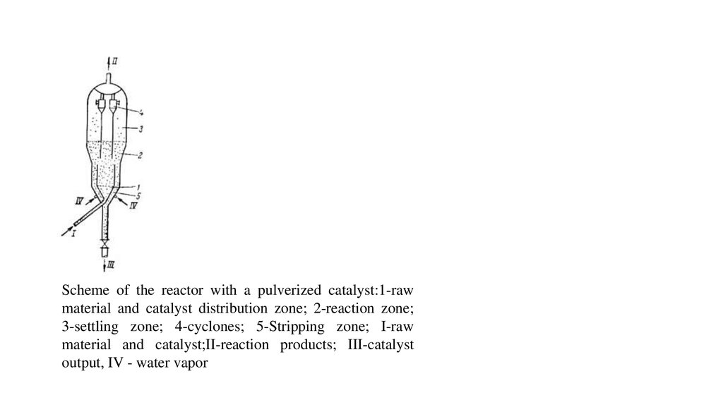
Scheme of the reactor with a pulverized catalyst:1-rawmaterial and catalyst distribution zone; 2-reaction zone;
3-settling zone; 4-cyclones; 5-Stripping zone; I-raw
material and catalyst;II-reaction products; III-catalyst
output, IV - water vapor