


")


 electronics
Similar presentations:


")


M4 - modicon m340. Аналоговое решение
1. M4 - MODICON M340 : Аналоговое решение
DiagnosticF
C
B
A
E
Language interface
D
BMX AMO 0210
BMX ART 0414
BMX AMI 0410
Generalities
M4 – Analog setting – 2006/06/06
2. A – Общее представление
Analog module – 2006/02/272
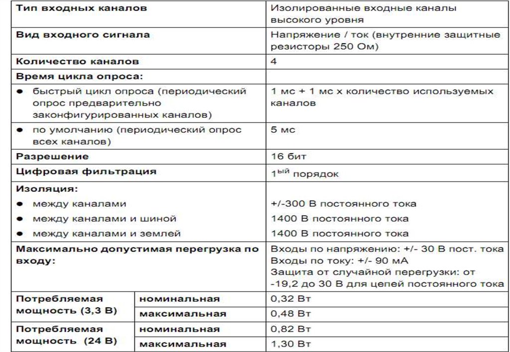
3. Модуль аналогового ввода BMX AMI 0410
Характеристика:Аналоговые модули имеют стандартную конструкцию и
представлены двумя типами модулей ввода :
4 канала в модуле BMX AMI 0410
Модуль BMX AMI 0410 предоставляет следующие
возможности:
1. +/-10 V
2. 0..10 V
3. 0..5 V / 0..20 mA
4. 1..5 V / 4..20 mA
5. +/- 5 V +/- 20 mA
BMX AMI 0410
Analog module – 2006/02/27
3
4.
Analog module – 2006/02/274
5.
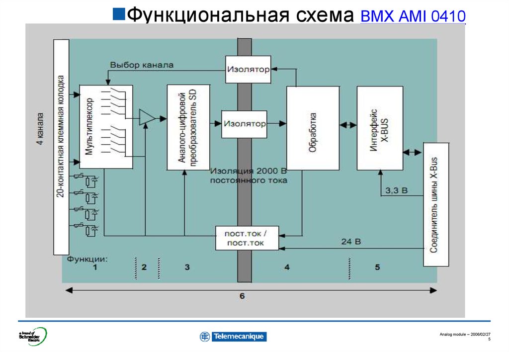
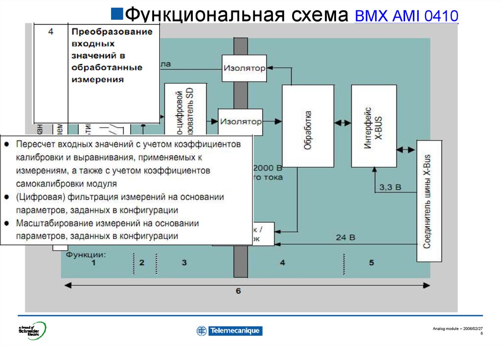
Функциональная схема BMX AMI 0410Analog module – 2006/02/27
5
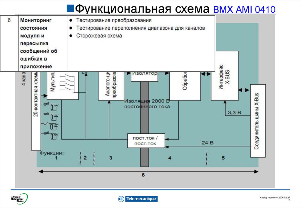
6.
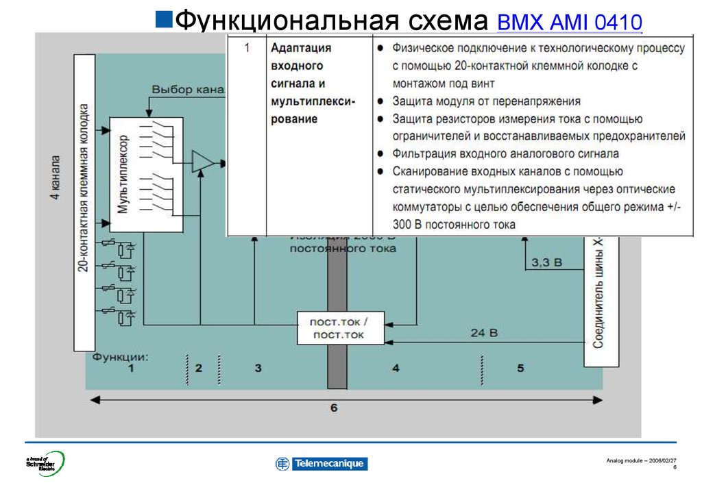
Функциональная схема BMX AMI 0410Analog module – 2006/02/27
6
7.
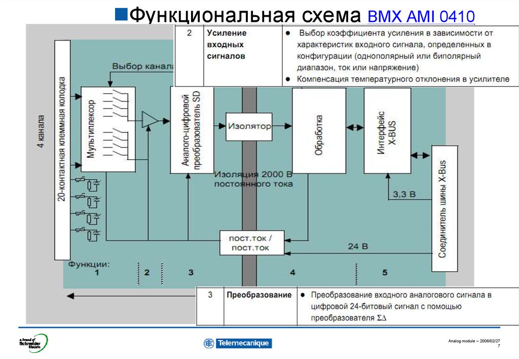
Функциональная схема BMX AMI 0410Analog module – 2006/02/27
7
8.
Функциональная схема BMX AMI 0410Analog module – 2006/02/27
8
9.
Функциональная схема BMX AMI 0410Analog module – 2006/02/27
9
10.
Функциональная схема BMX AMI 0410Analog module – 2006/02/27
10
11. Модуль аналогового ввода
Параметры BMX ART 0414 :Эти модули стандартного формата и представлены модулями двух
типов
измерительным устройством высокоуровневых сигналов.:
BMX ART 0414
4 - канальный модуль BMX ART 0414
BMX ART 0414 имеет изолированные входы. Каждый канал
имеет следующие характеристики :
1. Термопары B, E, J, K, L, N, R, S, T, U
2. Резисторы 0 – 400 Ohms ( 2/3 wires, 4 wires)
3.
0 – 3850 Ohms ( 2/3 wires, 4 wires)
4. +/-40mV, +/-80mV, +/-160mV, +/-320mV, +/640mV, 1280mV
5. Pt100 / Pt1000 (CEI or JIS ) ( 2/3 wires, 4 wires)
6. Ni100 / Ni 1000 (CEI or JIS ) ( 2/3 wires, 4
wires)
7. Cu 10
( 2/3 wires, 4 wires)
Analog module – 2006/02/27
11
12. Модуль аналогового вывода
Параметры:Модуль стандартного формата представлен одним модулем:
2 канала BMX AMO 0210
BMX AMO 0210 имеет два изолированных канала вывода.
Каждый канал имеет следующие характеристики:
1. Напряжение +/-10 V
2. Ток 0..20 mA
3. Ток 4..20 mA
BMX AMO 0210
Analog module – 2006/02/27
12
13. Модуль аналогового ввода
Moduleavailable
in the
launch
L12A.
Параметры:
Аналоговые модули стандартного формата представлены модулями
двух типов:
8 каналов BMX ART 0814
BMX ART 0414 module is a multi-range acquisition device with four inputs
isolated from each other. This module offers the following ranges for each
input,according to the selection made at configuration:
BMX ART 0814
RTD IEC Pt100/Pt1000 in 2,3 or 4 wires
US/JIS Pt100/Pt1000 in 2, 3 or 4 wires
Cu10, Ni100/Ni1000 in 2, 3 or 4 wires
thermocouple B, E, J, K, L, N, R, S, T, U
Voltage +/- 40 mV at +/- 1.28 V.
Analog module – 2006/02/27
13
14. Analog output module
Moduleavailable
in the
launch
L12A.
At a Glance :
Analog modules are standard format modules, this offer is made up of one
output Input module :
2 Analog Output and 4 Analog Input for the BMX AMM 0600 module
BMX AMM 0600
- 2 analog output not isolated from one other. It offers the following
ranges for each output:
Voltage +/-10 V
Current 0..20 mA and 4..20 mA
- 4 analog input offers the following range for each input:
+/-10 V,0..10 V,
0..5 V / 0..20 mA,
1..5 V / 4..20 mA,
+/- 5 V +/- 20 mA
Analog module – 2006/02/27
14
15. BMX AMI 0410 BMX ART 0414 BMX AMO 0210
Analog Module HardwareDescription
1
Module and channels state.
1
20-pin connector
2
-BMX AMI 0410
-BMX AMO 0210
40-pin connector
3
- BMX ART 0414
The display in front of the module allows
a quick diagnostic of the module, it is
shared in two part :
3
2
General information
State of the I/Os
Analog module – 2006/02/27
15
16. Display of Analog Module States
BMX AMI 0410BMX ART 0414
BMX AMO 0210
Display of Analog Module States
LEDs
RUN
ERR
I/O
0
1
2
3
Operationnal mode OK
Module out of service
Channel not configured
S
Internal fault
Not calibrated
BMX AMO 0210 only =>
BMX ART 0414 only =>
On
Communication fault with
CPU
S
Module not configured
S
Fault over range
S
S
S
S
Sensor fault
F
F
F
F
Quick Flashing
Slow Flashing
Off
Analog module – 2006/02/27
16
17. BMX AMI 0410 BMX ART 0414 BMX AMO 0210
Specific functionSensor Alignment
Процесс "выравнивания" состоит из устранения систематического смещения,
характерного для конкретного датчика в районе некоторой специфичной
рабочей точки.
XXX.ALIGNMENT_OFFSET
Данная операция компенсирует ошибки, связанные с процессом.
-Замена модуля не требует повторной настройки выравнивания.
-Однако, при замене датчика или при изменении значения рабочей точки датчика
требуется новая настройка выравнивания.
Преобразованное значение:
Линия преобразования
после выравнивания
Линия преобразования до
выравнивания
5150
5000
Входное значение
5V or 1000°c
Analog module – 2006/02/27
17
18. B – BMX AMI 0410
Analog module – 2006/02/2718
19. BMX AMI 0410: Hardware
Analog module – 2006/02/2719
20. BMX AMI 0410
Module typeGeneral Characteristics
BMX AMI 0410
Voltage and current input ( Internal resistor protected
until +/- 30Vdc)
Input
4
Channel number
periodic acquisition for the declared channels used
1 ms + 1 ms for each channel used
16 bits
Resolution
1st Order
Numeric filter
Isolation
4 Analog isolated input high level
Between channel
+/- 300 Vdc
Between channel and bus
2000 Vdc
Between channel anf ground
2000 Vdc
Max tension
+ / - 30 Vdc
Max Current
+ / - 30 mA
Analog module – 2006/02/27
20
21. BMX AMI 0410
measure Characteristics+/-10 V, 0..10 V, 0..5 V / 1..5 V,
+/- 5 V
0..20 mA, 4..20 mA, +/- 20 mA
+ / - 11,4V
+ / - 30 mA
0,35 mV
0,92 µA
Internal resistor
-
250 Ohms
Resistor occurancy
-
0.1% - ( 25 ppm/°C)
0,05 % de Full Scale
0,1 % de Full Scale
0,15 % de Full Scale
0,3 % de Full Scale
15 ppm / °c
30 ppm / °c
Measurement range
Max value
Resolution ( 16 bits )
Measurement error:
1. at 25°C
2. Maximum in the range (0..60°C)
Drift in temperature
Analog module – 2006/02/27
21
22. BMX AMI 0410
WiringCOM 0
2
1
IN_Voltage
Channel 0
NC
4
3
IN_Current
channel 0
NC
6
5
NC
COM 1
8
7
IN_Voltage
Channel 1
NC
10
9
IN_Current
channel 1
COM 2
12
11
IN_Voltage
Channel 2
NC
14
13
IN_Current
Channel 2
NC
16
15
NC
COM 3
18
17
IN_Voltage
Channel 1
NC
20
19
IN_Current
Channel 1
Analog module – 2006/02/27
22
23. BMX AMI 0410
Wiring+
Example
COM 0
2
1
IN_V Ch 0
NC
4
3
IN_I ch 0
NC
6
5
NC
COM 1
8
7
IN_V Ch 1
NC
10
9
IN_I Ch 1
COM 2
12
11
IN_V Ch 2
NC
14
13
IN_I Ch 2
V
-
+
-
The TERMINAL block is
provided with accessories
for Keying.
NC
16
15
NC
COM 3
18
17
IN_V Ch 1
NC
20
19
IN_I Ch 1
Analog module – 2006/02/27
23
24. BMX AMI 0410
WiringBMX AMI 0410
At a Glance :
The TELEFAST ABE-7CPA410 accessory is a base unit used for the
connection of sensors. It has the following functions :
BMX FCA xx0
Supply, channel by channel, the 4 to 20 mA sensors with a
protected 24 V voltage, limited in current to 25 mA, while
maintaining isolation between the channels.
Protect current reading resistors that are integrated in
TELEFAST against overvoltage.
ABE7CPA410
Analog module – 2006/02/27
24
25. BMX AMI 0410
WiringBMX AMI 0410
BMX FCA xx0
ABE7CPA410
Analog module – 2006/02/27
25
26. Подключение через блоки быстрого монтажа TELEFAST
Analog module – 2006/02/2726
27. Использование датчиков, имеющих потенциал относительно земли
Analog module – 2006/02/2727
28. BMX AMI 0410
WiringAnalog module – 2006/02/27
28
29.
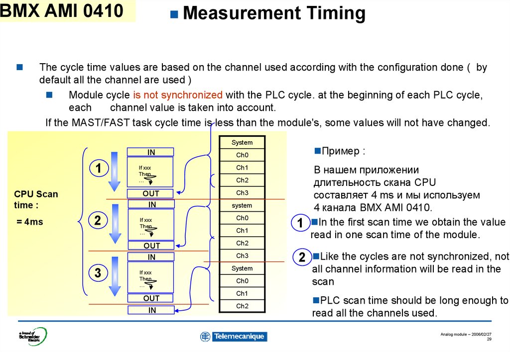
BMX AMI 0410Measurement
Timing
The cycle time values are based on the channel used according with the configuration done ( by
default all the channel are used )
Module cycle is not synchronized with the PLC cycle. at the beginning of each PLC cycle,
each
channel value is taken into account.
If the MAST/FAST task cycle time is less than the module's, some values will not have changed.
System
IN
1
CPU Scan
time :
= 4ms
If xxx
Then..
…
OUT
IN
2
If xxx
Then..
…
OUT
IN
3
If xxx
Then..
…
OUT
IN
Пример :
Ch0
Ch1
Ch2
Ch3
system
Ch0
Ch1
1
В нашем приложении
длительность скана CPU
составляет 4 ms и мы используем
4 канала BMX AMI 0410.
In the first scan time we obtain the value
read in one scan time of the module.
Ch2
Ch3
System
Ch0
Ch1
Ch2
2
Like the cycles are not synchronized, not
all channel information will be read in the
scan
PLC scan time should be long enough to
read all the channels used.
Analog module – 2006/02/27
29
30. BMX AMI 0410: Software
Analog module – 2006/02/2730
31. BMX AMI 0410
ConfigurationScale for 0 to
100%
The mathematical formula used is as follows:
mesF( n ) =α x mesF( n-1) + ( 1 – α ) x valg ( n )
The range used
Check
Above/Below
overflow limit
The module
be used
: 4
Normal
cycle can
: In this
case in
the
Channels
be :scanned,
selected
Normal will
cycle
In this case
the 4 or
Channelsnot.
will be use.
FastCycle
Cycle: :InInthis
thiscase
casewe
wewill
willselect
scan
Fast
onlythe
thechannel
selectedused
channel
Analog module – 2006/02/27
31
32. BMX AMI 0410
Debugscreen
The debug screen displays the following parameters :
left
Symbol
used for
the channel
Forced or
Unforced a
value
The value
read
The filter
used
The value of
the offset
Analog module – 2006/02/27
32
33. C – BMX ART 0414
Analog module – 2006/02/2733
34. BMX ART 0414/814: Hardware
Analog module – 2006/02/2734
35. Описание функций
Analog module – 2006/02/2735
36. Описание функций
Analog module – 2006/02/2736
37. BMX ART 0414
Module typeGeneral Characteristics
BMX ART 0414
Input
4 Analog isolated input
RTD, thermocouple, voltage and resistor
4
Channel number
400 ms if one channel use RTD
200 ms if we use only the Thermocouple
periodic acquisition
15 bits + sign
Resolution
1st order
Numeric filter
Cold junction compensation without TELEFAST
Channel 0 configured in RTD
Channel 0 configured in Termocouple and a RTD (2
wires) connected also on the channel 0.
Cold junction compensation with a TELEFAST
(ABE 7CPA 412)
Isolation
Specific input dedicated for the cold junction
compensation if we use the telefast ABE 7CPA 412 (
with the sensor integrated )
Between channel
750 Vdc
Between channel and bus
1500 Vdc
Between channel anf ground
750 Vdc
Analog module – 2006/02/27
37
38. BMX ART 0414
measure Characteristics: Voltage
+/- 40mV, +/- 80mV, +/- 160mV,
+/- 320mV, +/- 640mV, +/- 1280mV,
400 Ohms ( 2 or 3 wires )
3850 Ohms ( 2 or 3 wires )
Max value
+ / - 102 %
+ / - 100 %
Resolution
V range / 2 exp 14
V range / 2 exp 14
Measurement range
Internal resistor
Resistor occurancy
Measurement error:
1. at 25°C
2. Maximum in the range (0..60°C)
Drift in temperature
10 M ohms
0,05 % de Full Scale
0,15 % de Full Scale
0,12 % de Full Scale
0,2 % de Full Scale
30 ppm / °c
25 ppm / °c
Analog module – 2006/02/27
38
39. BMX ART 0414
Measurement rangemeasure Characteristics :
RTD
Pt100
Pt1000
CEI : -200 + 850°C
US/JIS : -100 +450°C
Ni100
-100 + 260°C
Ni1000
-60 + 180°C
0.1 °C
Resolution
Detection type
Measurement error:
1. at 25°C
2. Maximum in the range (0..60°C)
Cu10
Open circuit / Out range value
+/- 1 °C
+/- 2 °C
+/- 1 °C
+/- 2 °C
+/- 4 °C
+/- 4 °C
+/- 1 °C
+/- 1 °C
+/- 1 °C
+/- 1 °C
Analog module – 2006/02/27
39
40. BMX ART 0414
Measurement rangeMeasurement range
Resolution
Detection type
Measurement error:
1. at 25°C
2. Maximum in the range (0..60°C)
Measure Characteristics :
Thermocouple
B
E
J
K
L
-130
+1820°C
-270
+1000°C
-200 +760°C
-270 +
1370°C
-200 + 900°C
N
R
S
T
U
-270
+1300°C
-50 +1665°C
-50 + 1665°C
-270 + 400°C
-200 + 600°C
0.1 °C
Open circuit
+/-3 °c ( J,K,E,T,U) +/-5°c ( S,R,B,N,L )
+/-5 °c ( J,K,E,T,U) +/-8°c ( S,R,B,N,L )
This error is given with the TELEFAST Cold junction compensation
Eg : If we use the PT100 input on the channel 0 the error will be divise by 2
Analog module – 2006/02/27
40
41. BMX ART 0414
WiringCold junction
connection when
using
TELEFAST
NC
40
DTC
CJ+
39
18
CJ0
CJ-
38
17
MS-
MS+
37
16
EX-
EX+
36
15
NC
NC
35
14
NC
NC
34
EX- EX+
13
NC
NC
33
MS- MS+
current generator
12
MS-
MS+
32
EX+
NC
thermocouple
input
10
EXNC
31
9
NC
NC
29
8
NC
NC
28
7
MS-
MS+
27
6
EX-
EX+
26
5
NC
NC
25
4
NC
NC
24
3
NC
NC
23
2
MS-
MS+
22
1
EX-
EX+
21
20
NC
19
11
30
Analog module – 2006/02/27
41
42. BMX ART 0414
Cold junctionWiring
NC
40
DTC
CJ+
39
18
CJ0
CJ-
38
17
MS-
MS+
37
16
EX-
EX+
36
15
NC
NC
35
14
NC
NC
34
13
NC
NC
33
12
MS-
MS+
32
11
EX+
NC
31
10
EXNC
9
NC
NC
29
8
NC
NC
28
7
MS-
MS+
27
6
EX-
EX+
26
5
NC
NC
25
4
NC
NC
24
3
NC
NC
23
2
MS-
MS+
22
1
EX-
EX+
21
20
NC
19
connection when
using TELEFAST
Thermocouple
RTD 2 Wires
30
RTD 3 Wires
RTD
4 Wires
Analog module – 2006/02/27
42
43. BMX ART 0414
WiringBMX ART 0414
BMX FCA xx2
Cold junction connection is
provided by a specific device
in SUBD0
ABE7CPA412
( pin 21, 22, 23, 24 )
Analog module – 2006/02/27
43
44. BMX ART 0414
COLDJUNCTION
Compensation:
The module give three methods of Cold junction compensation.
1.
The external compensation of the module is performed in the TELEFAST
ABE-7CPA412 accessory.
2.
It is possible to increase the precision of the compensation by using a 3-wire Pt100
probe directly connected to channel 0 on the module or connected to the
TELEFAST terminal blocks. Channel 0 is thus dedicated to the cold junction
compensation of channels 1, 2 and 3.
3.
It is equally possible, to maintain channel 0 as a thermocouple input by using a 2wire Pt100 probe.
The wiring would then look like this:
Termocouple
Channel 0
RTD ( 2 wires )
Analog module – 2006/02/27
44
45.
Why we need a coldjunction compensation with
the thermocouple ?
A thermocouple is made with the
association with two metallic
conductor
This association provide a FEM
according with the temperature.
This temperature e(θ,0) is
known if the cold junction θa egal
0°c. But in our case the cold
junction is never egal to 0°C so
we must measure and apply a
correction called :
cold junction compensationThis
compensation is applied
according with the formula :
e(θ,0) = e(θ, θa) + e(θa,0)
20
NC
NC
40
19
DTC
CJ+
39
18
CJ0
CJ-
38
17
MS-
MS+
16
EX-
θaEX+
37
36
15
NC
NC
35
14
NC
NC
34
13
NC
NC
33
12
MS-
MS+
32
11
EX+
NC
31
10
EXNC
9
NC
NC
29
8
NC
NC
28
7
MS-
MS+
27
6
EX-
EX+
26
5
NC
NC
25
4
NC
NC
24
3
NC
NC
23
2
MS-
MS+
22
1
EX-
EX+
21
Cold junction
connection
Thermocouple
θ
30
Analog module – 2006/02/27
45
46.
What is the difference between :- 2 wires / 3 wires / 4 wires
RTD ?
4
wires :: In
In this
this case
case the
current
2 wires
we use
the
3
generator
same wireand
for :the measure are
separate one wire is used for
the current
current generator
andgenerator
for the measure
The measure is given without error.
andit’s mandatory to use
For this wiring
exactly thethe
same
resistor for the three
measure
wires.
so the measure is given with an error
The
provideofathe
specific
due module
to the resistor
wire used to
algorithmic
to
calculate
the
resistor of
provide the current.
the wire and compense automatically
Useerror
this wiring
a short wires
the
due towith
the resistor
NC
40
DTC
CJ+
39
18
CJ0
CJ-
38
17
MS-
MS+
37
16
EX-
EX+
36
15
NC
NC
35
14
NC
NC
34
13
NC
NC
33
12
MS-
MS+
32
EX+
NC
31
20
NC
19
11
t
10
EXNC
9
NC
NC
29
8
NC
NC
28
7
MS-
MS+
27
6
EX-
EX+
26
5
NC
NC
25
4
NC
NC
24
3
NC
NC
23
2
MS-
MS+
22
1
EX-
EX+
21
t
t
i
i
RTD 2 Wires
30
i
i
RTD 3 Wires
i
RTD 4 Wires
i
Analog module – 2006/02/27
46
47. BMX ART 0414: Software
Analog module – 2006/02/2747
48. BMX ART 0414
ConfigurationConfiguration
Type of
measure
This
function
is dedicated
to eliminate
Selecting
where
the cold junction
is a perturbation coming from
the
power supply .
realized
Rule :
If the electrical supply network = 60hz =>selecting 60 hz (Ex: US)
If the electrical supply network = 50hz =>selecting 50 hz (Ex: Fr)
We use or not the channel .
Remenber : 1 channel RTD used Scantime 400ms
Only thermocouples used Scantime 200ms
Analog module – 2006/02/27
48
49. BMX ART 0414
ConfigurationThe mathematical formula used is as follows:
mesF( n ) =α x mesF( n-1) + ( 1 – α ) x valg ( n )
Scale
asked
Overflow automatically
Scale
calculed
asked according with the
Scale
Overflow automatically
calculated according to the
scaling values
Analog module – 2006/02/27
49
50. Значения степени фильтрации для TSX AEY 414 (Premium)
Analog module – 2006/02/2750
51. BMX ART 0414
Debugscreen
The debug screen displays the following parameters :
Symbol
used for
the channel
Foreced or
Unforced a
value
The value
read
The filter
used
The value of
the offset
Analog module – 2006/02/27
51
52. D – BMX AMO 0210
Analog module – 2006/02/2752
53. BMX AMO 0210: Hardware - модуль аналогового вывода
BMX AMO 0210: Hardware модуль аналогового выводаAnalog module – 2006/02/27
53
54. Функциональная схема модуля вывода
Analog module – 2006/02/2754
55.
Analog module – 2006/02/2755
56. BMX AMO 0210
General CharacteristicsBMX AMO 0210
BMX AMO 0210
Module type
2 Analog isolated output high level
Voltage and current output
output
2
Channel number
Response time
Less than 1ms
Resolution
15 bits + Signe
Internal power supply
Power supply for Output
Short circuit and overload
Protected
Isolation
Between channel
1400 Vdc
Between channel and bus
2000 Vdc
Between channel anf ground
2000 Vdc
Measurement error:
1.at 25°C
2.Maximum in the range (0..60°C)
0,15% de Full Scale
0,25 % de Full Scale
Analog module – 2006/02/27
56
57. BMX AMO 0210
Measure Characteristics+/-10 V
0..20 mA, 4..20 mA,
Max value
+ / - 11,25V
- 0.4 mA / 24 Ma (+/-20%)
Resolution
0,68 mV
0,6 µA
1 KΏ mini
600 Ώ max
Short circuit
Open circuit
Measurement range
Load impedance
Detection
Overflow control
ERR
ERR
hard
+/-10V
soft
Nominal range
soft
hard
-11 250
-11 000
-10 000
10 000
11 000
11 250
0..20 mA
-2000
-1000
0
10 000
11 000
12 000
4 .. 20 mA
-1600
-800
0
10 000
10 800
11 600
Analog module – 2006/02/27
57
58. BMX AMO 0210
WiringNC
NC
COM 0
COM 0
NC
NC
NC
NC
NC
The TERMINAL block is
provided with accessories
for keying
2
NC
1
2
4
3
OUT ch 0
4 U_I 3
6
5
NC
6
8
1
NC 0
NC
1
NC
2
NC
1
NC
4
NC
1
NC
6
COM 1
1
COM 1
8
NC
NC 2
0
+
OUT channel 0
Voltage
- _Current
5
NC
7
NC
9
NC
11
NC
13
NC
15
NC
NC
7
8
NC
9
10
1
1
1
3
1
5
1
7
1
9
NC
1
NC
12
NC
14
16
NC
OUT ch 1
18 U_I17
20
NC
19
-
+
OUT channel 1
Voltage _Current
NC
Analog module – 2006/02/27
58
59. BMX AMO 0210: Software
Analog module – 2006/02/2759
60. BMX AMO 0210
ConfigurationA user defined scaling
factor
and
High / Low overflows
Module refresh
may be selected
The range
selected in FAST task
or
in MAST task
Analog module – 2006/02/27
60
61. BMX AMO 0210
ConfigurationConfiguration
Control or not
the wiring
Select FALLBACK this action
will be use if :
1.
2.
3.
CPU in STOP mode
Cold start
Communication fault
Analog module – 2006/02/27
61
62. BMX AMO 0210
Debugscreen
The debug screen displays the following parameters :
left
Symbol
used for
the
channel
Forced
or
Unforced
a value
The value
Write
Fallback
value used
on fault
The value for the
alignement
Analog module – 2006/02/27
62
63. E – Language interface
Analog module – 2006/02/2763
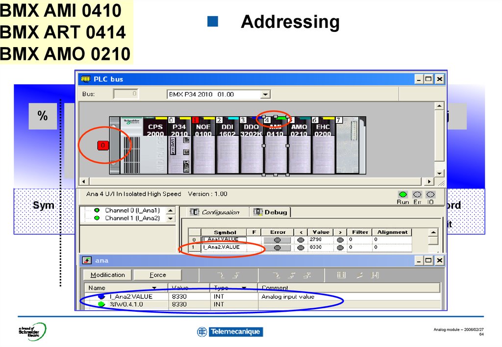
64.
BMX AMI 0410BMX ART 0414
BMX AMO 0210
%
I, Q,
M, K
Sym
X, W, D
r
Addressing
m
c
i
j
channel
word
word
rank
bit
F
Object type
rack
module
position
Analog module – 2006/02/27
64
65. BMX AMI 0410 BMX ART 0414 BMX AMO 0210
IODDT on the analog moduleThree separed IODDT are provided
with in order to manage all the
Analog functionnalities:
1. BMX IODDT Analog Input
2. BMX IODDT Temperature Input
3. BMX IODDT Analog Output
Analog module – 2006/02/27
65
66. F – Analog modules diagnostics
Analog module – 2006/02/2766
67. BMX AMI 0410
Diagnosticscreen
The debug screen provides information to diagnose a problem.
The Error touch
provide a direct
access to a easy
diagnostic
If the fault is a over
range these lamps
provide if the value
is over or under the
limit
left
left
In this example the
fault is due to a
overflow
Analog module – 2006/02/27
67
68. BMX ART 0414
Diagnosticscreen
The debug screen provides information to diagnose a problem.
left
The Error touch
provide a direct
access to a easy
diagnostic
IfIfthe
thefault
faultis
isaaover
over
range
rangethese
theselamps
lamps
provide
provide ififthe
thevalue
value
is
isover
over or
orunder
underthe
the
limit
limit
In this example the
fault is due to a
overflow
Analog module – 2006/02/27
68
69. BMX AMO 0210
Diagnosticscreen
The debug screen provides information to diagnose a problem.
left
The Error touch
provide a direct
access to a easy
diagnostic
In this example the
fault is due to a
SHORT CIRCUIT
Analog module – 2006/02/27
69
70. Analog offer
Analog module – 2006/02/2770