


 physics
 electronics
Similar presentations:


 & Compressor Dehydrator")


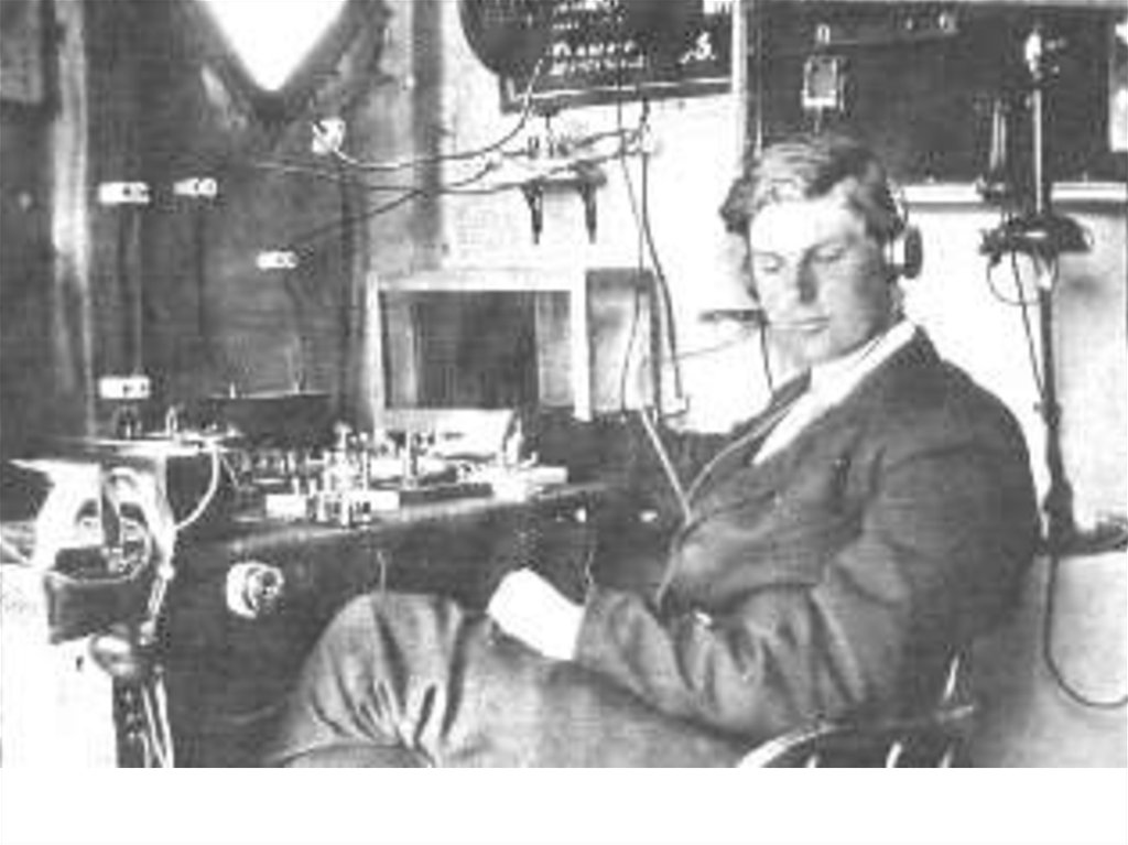
Low-Band Receive Antennas
1. Low-Band Receive Antennas
How to hear that great DX that you’remissing on 40, 80 and 160!
Al Penney
VO1NO / VE3
2. Tonight’s Topics…
Introduction
Receiving Basics
RX Loops
Elongated Terminated Loops
–
–
–
–
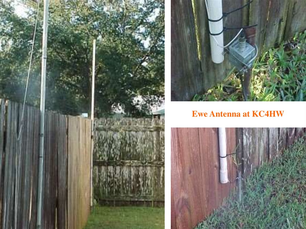
EWE Antenna
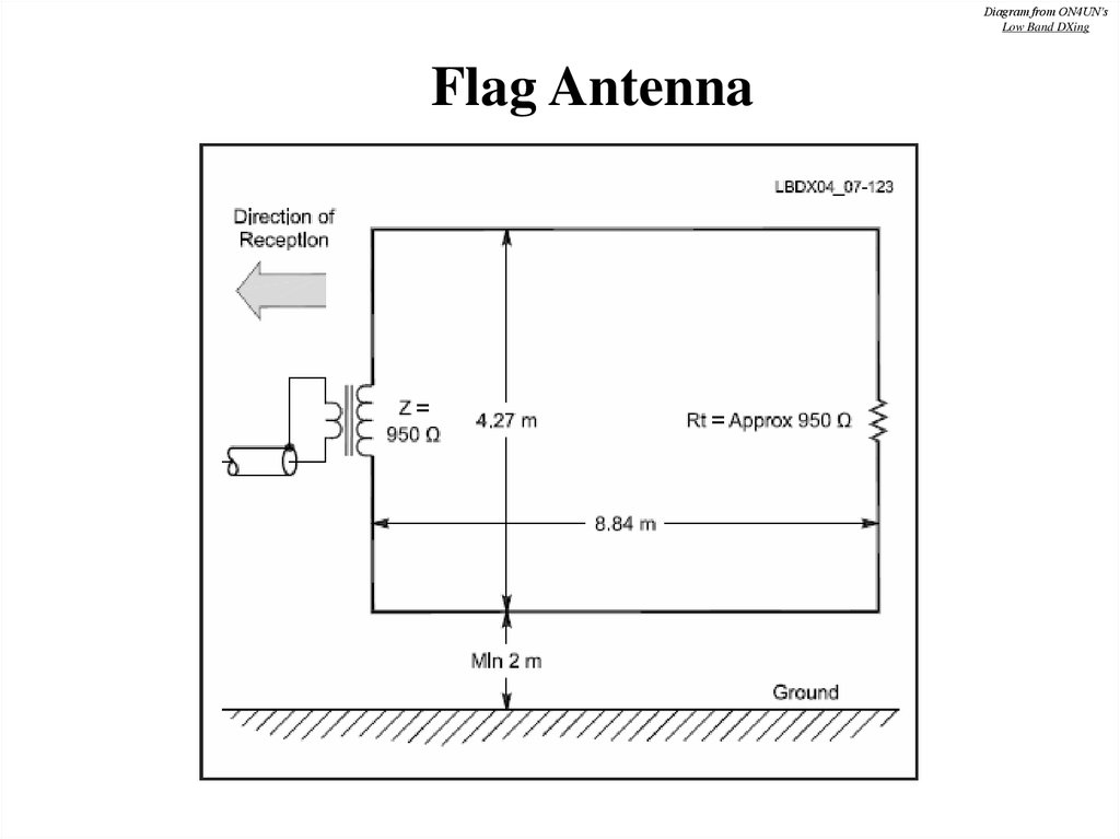
Flag Antenna
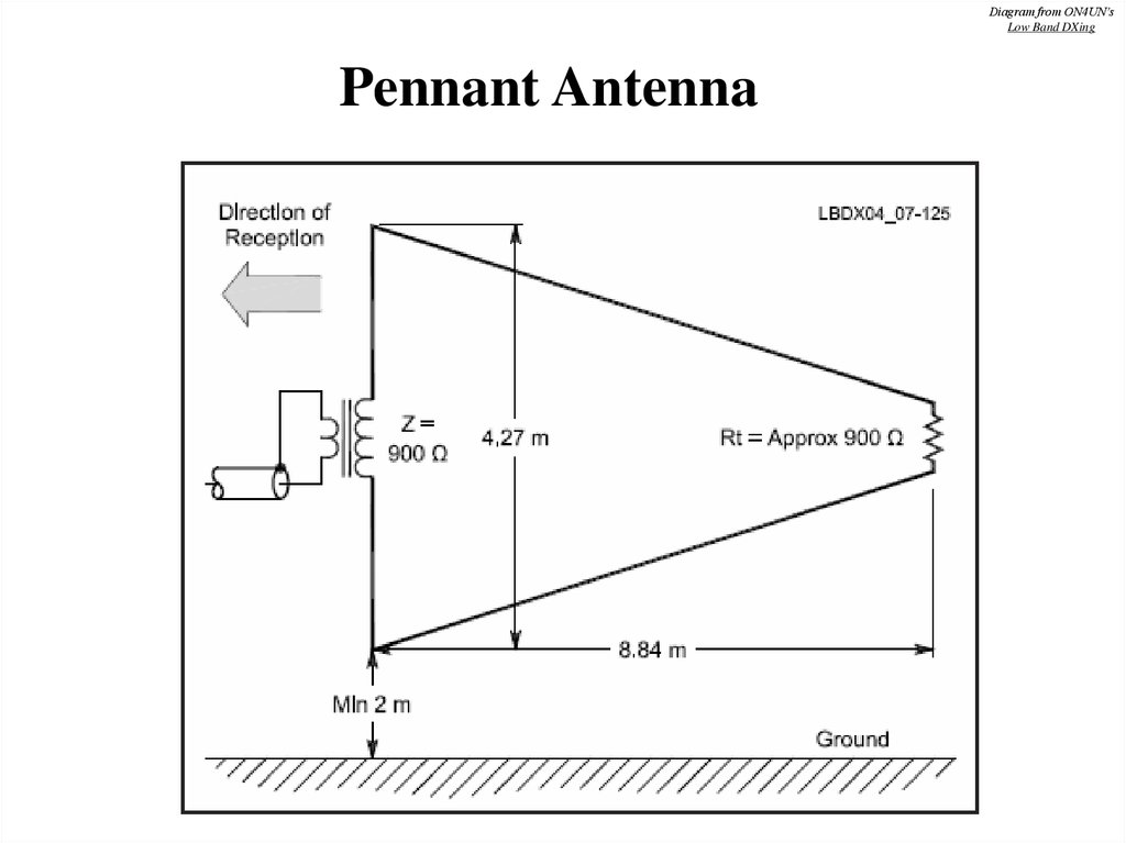
Pennant Antenna
K9AY Loop
• Beverages
3.
4. Why do we need separate TX and RX antennas?
• Because, they have different requirements:– TX antennas need to deliver strongest possible
signal into target area compared to other antennas.
– Efficiency and gain are most important factors.
– RX antennas need to have best Signal to Noise
Ratio (SNR) – gain and efficiency are not
necessary.
5.
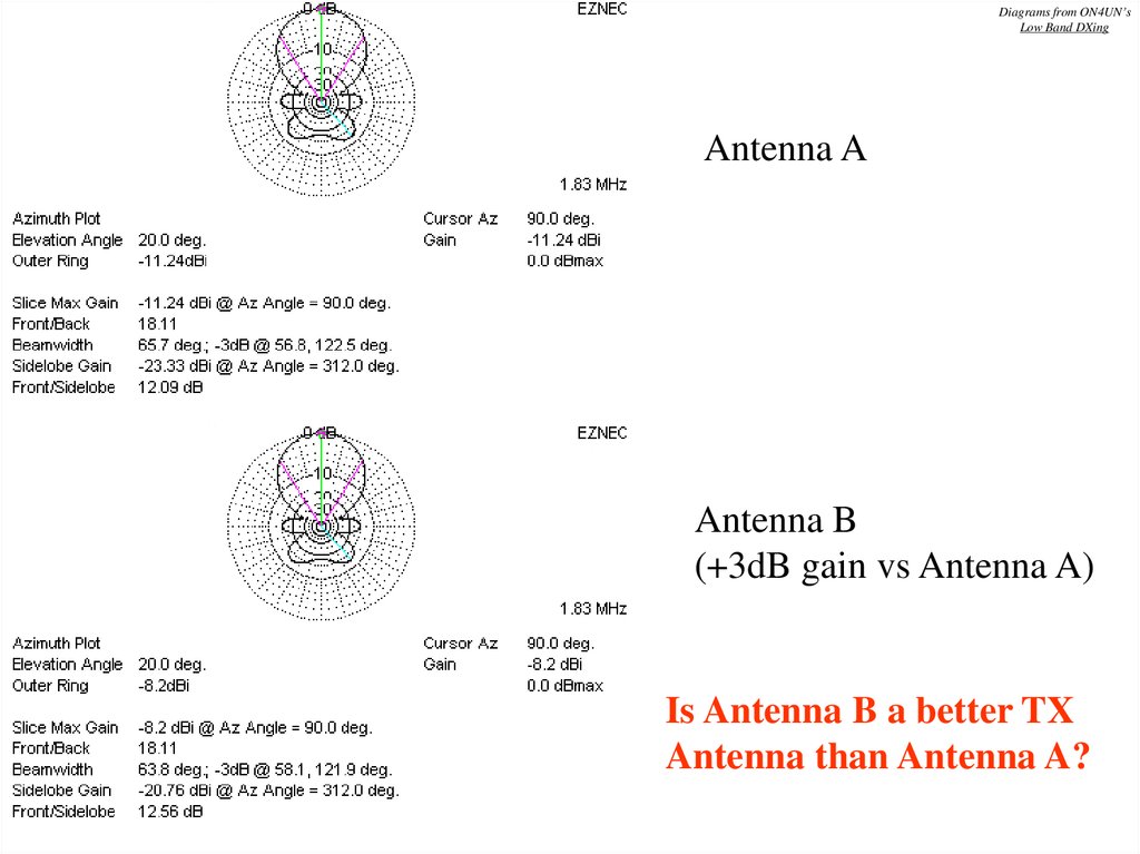
Diagrams from ON4UN’sLow Band DXing
Antenna A
Antenna B
(+3dB gain vs Antenna A)
Is Antenna B a better TX
Antenna than Antenna A?
6.
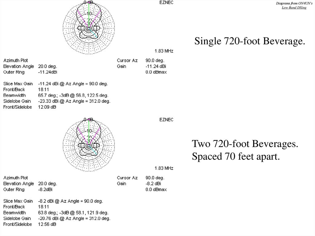
Diagrams from ON4UN’sLow Band DXing
Single 720-foot Beverage.
Two 720-foot Beverages.
Spaced 70 feet apart.
7.
• Gain single Beverage:-11.2 dBi
• Gain two Beverages (70-ft sp): -8.2 dBi
• So, a pair of Beverages (with 70-ft spacing)
has 3 dB gain over a single Beverage.
• But, has anything actually been gained in
terms of Signal/Noise ratio?
8. NO – nothing has been gained!
• The pattern is still practically identical– Front/Back is the same
– Front/Side is within 0.47dB
• Unwanted noise is external to the antenna.
Because the directivity of the two antenna systems
is the same, the Signal/Noise ratio is exactly the
same for both.
• We must use Directivity when comparing RX
Antennas, not gain.
9. How much Negative Gain can we tolerate with RX antennas?
• Modern receivers are very sensitive.• If you can easily hear an increase in
background noise when switching from a
dummy load to an RX antenna under
quietest conditions, then gain is sufficient.
• Minus10 to minus 20 dBi Gain is generally
fine for most occasions.
10. Noise
• The sum of all unidentified signals(thunderstorms, man-made, cosmic etc.).
• Requires its own presentation!
• RX antennas reduce noise through:
–
–
–
–
Directivity
Null placement
Noise canceling devices
Height
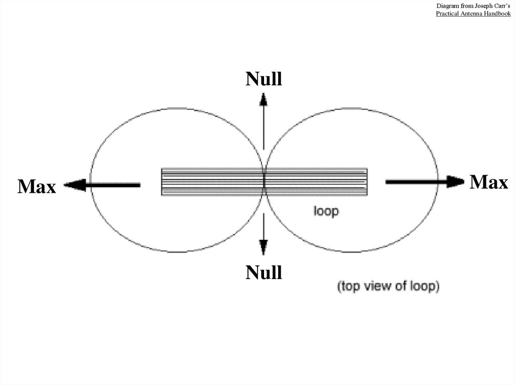
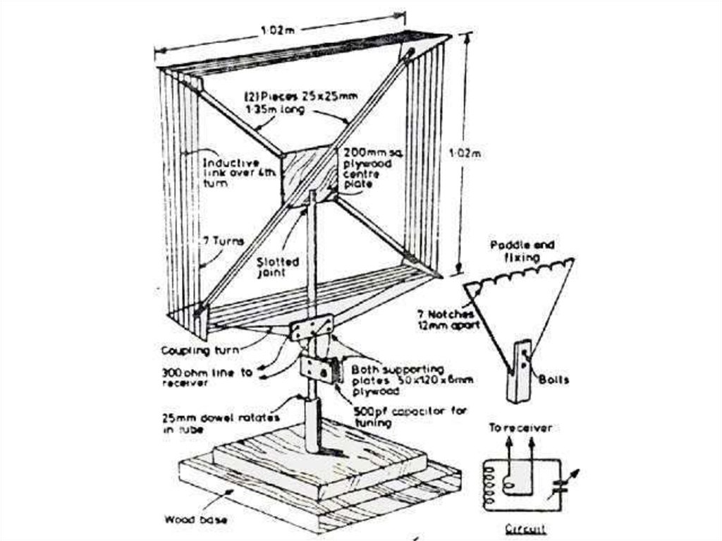
11. Receive Loop Antennas
12.
Diagram from Joseph Carr’sPractical Antenna Handbook
Null
Max
Max
Null
13.
14.
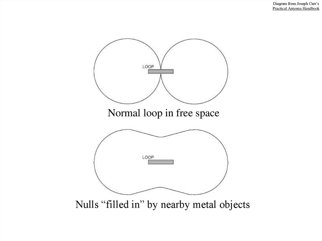
Diagram from Joseph Carr’sPractical Antenna Handbook
Normal loop in free space
Nulls “filled in” by nearby metal objects
15.
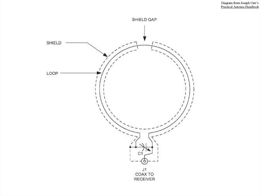
Diagram from Joseph Carr’sPractical Antenna Handbook
16.
Diagram from Joseph Carr’sPractical Antenna Handbook
17.
Diagram from Joseph Carr’sPractical Antenna Handbook
18. Receive Loops Summary
• Pros– Small, lightweight
– Easy to build
– Sharp null in 2
directions
• Cons
– Poor sensitivity
– Broad RX pattern
– Often next to noise
source in shack
Receive loops can be a useful tool in some
situations, but are probably better suited for
SWL and BCB/LF Beacon DX’ing.
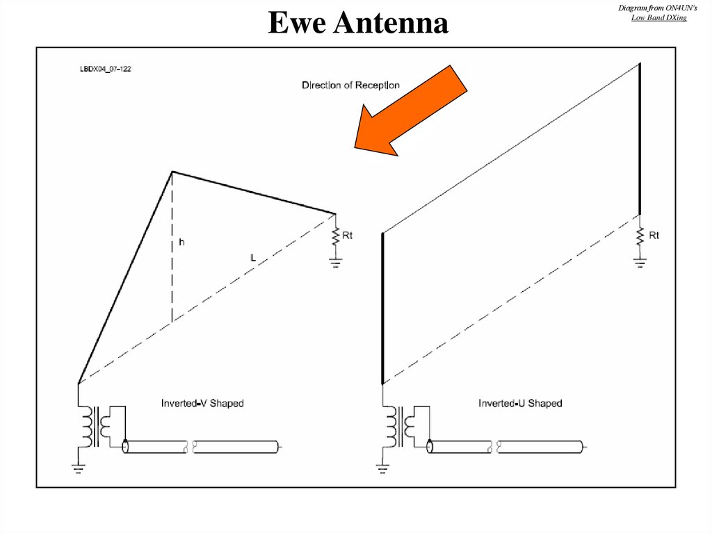
19. Elongated Terminated Loops
• Include Ewe, Flag, Pennant and K9AY• Terminated loop produces a cardioid pattern
• Depth and angle of null depend on loop shape
20. Theory of Operation
• Despite the shape, actually a pair of verticals• Feedline on top and bottom gives crossfire phasing
towards feedpoint when elements closer than ¼ Lambda
• Terminating resistor is equal to feedpoint impedance, and
ensures equal current throughout
• Thus, vertical elements have phase difference of 180 deg
plus electrical length of connecting wires (slightly more
than element spacing)
• This gives the cardioid pattern
Direction of Reception
Terminating Resistor
Matching X’fmer
Coax
21.
Ewe AntennaDiagram from ON4UN’s
Low Band DXing
22.
Ewe Antenna at KC4HW23.
Diagram from ON4UN’sLow Band DXing
Flag Antenna
24.
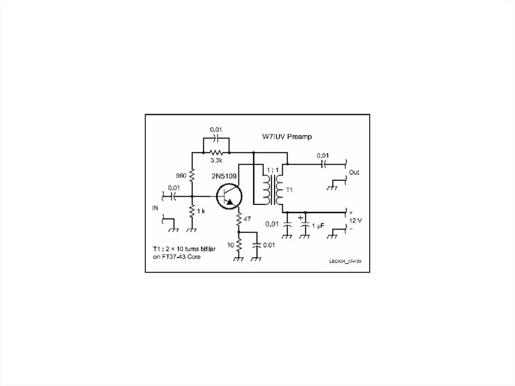
www.qsl.net/w7iuv/25.
Diagram from ON4UN’sLow Band DXing
Pennant Antenna
26.
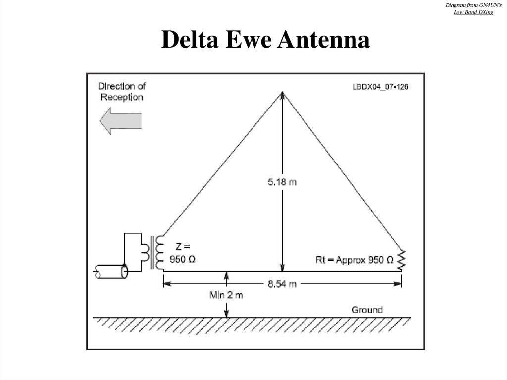
Diagram from ON4UN’sLow Band DXing
Delta Ewe Antenna
27.
Diagram from ON4UN’sLow Band DXing
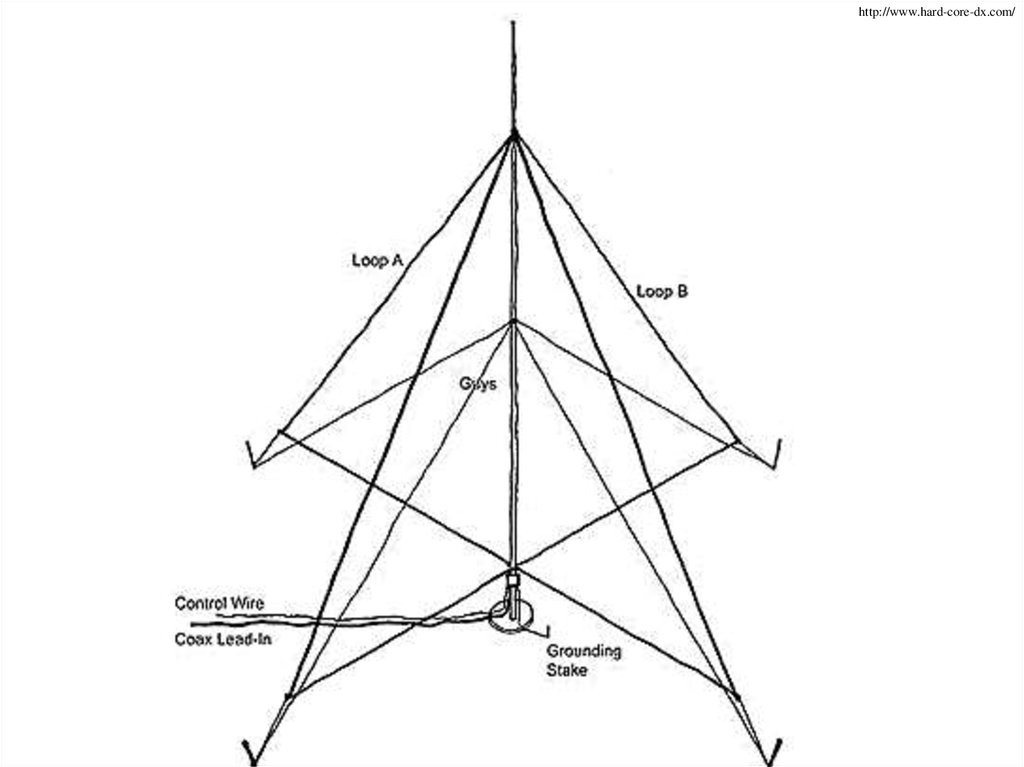
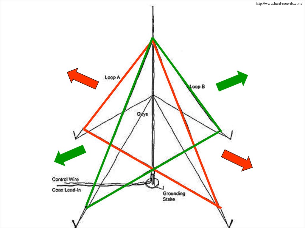
K9AY Antenna
28.
http://www.hard-core-dx.com/29.
http://www.hard-core-dx.com/30.
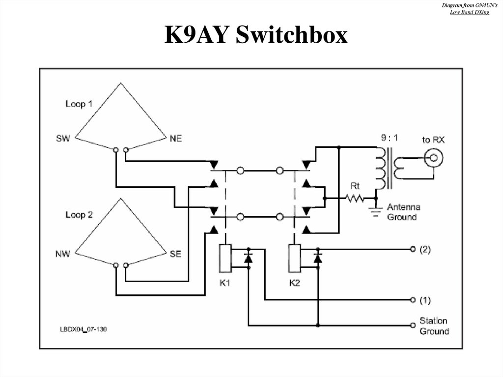
Diagram from ON4UN’sLow Band DXing
K9AY Switchbox
31.
Diagram from ON4UN’sLow Band DXing
K9AY Control Box
32.
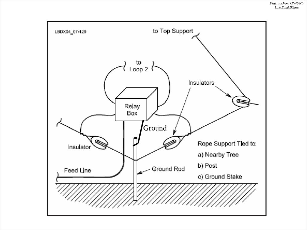
Diagram from ON4UN’sLow Band DXing
Ground
33.
Photo from ON4UN’sLow Band DXing
34.
Diagram from ON4UN’sLow Band DXing
35. Feeding Elongated Loops
• Impedances range from 500 Ohms in K9AY,to 950 Ohms in Deltas and Flags.
• Important characteristics:
– Lowest possible capacitive coupling between
primary and secondary windings.
– Low loss, as signals are weak
– Good SWR if you want to phase loops into an
array of loops
36.
Diagram from ON4UN’sLow Band DXing
I use binocular cores made from
#73 material. Separate windings
ensure low coupling, and good
balance. Other designs are
possible.
Transformation
High-Z
Low-Z
500 Ω to 75 Ω
2 passes (1 turn) 5 passes
500 Ω to 50 Ω
2 passes (1 turn) 6 passes
950 Ω to 75 Ω
2 passes (1 turn) 7 passes
37.
Diagram fromwww.w8ji.com
38. Elongated Loop Summary
• Pros– Small footprint
– Simplicity
– Can be phased to
improve performance
– Much better than
listening to a vertical!
• Cons
– Insensitive, may
require a preamp
– Directivity not as good
as a Beverage
– Feedline prone to noise
pickup
Although not as good as Beverage antennas,
Elongated Loops offer good performance
for people who don’t have much room.
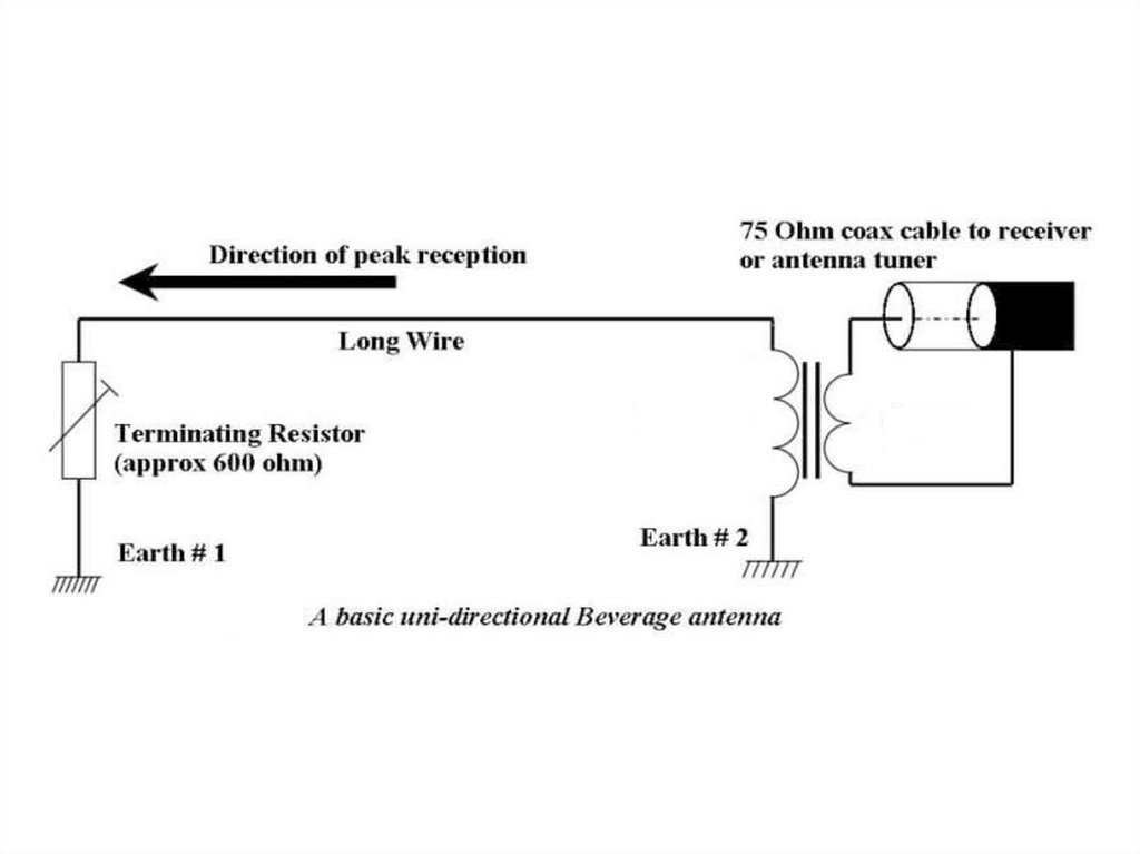
39. The Beverage Antenna!
40.
41.
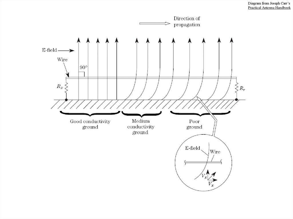
Diagram from Joseph Carr’sPractical Antenna Handbook
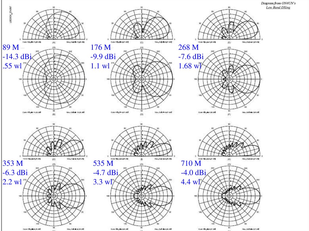
42. Influence of Length
• Following slide shows EZNEC results for aBeverage with following characteristics:
–
–
–
–
–
2 meters high
Over good ground
600 Ohm termination
0.55 to 4.4 wavelength
160 M band
43.
Diagram from ON4UN’sLow Band DXing
89 M
-14.3 dBi
.55 wl
353 M
-6.3 dBi
2.2 wl
176 M
-9.9 dBi
1.1 wl
535 M
-4.7 dBi
3.3 wl
268 M
-7.6 dBi
1.68 wl
710 M
-4.0 dBi
4.4 wl
44.
45. How High?
• Not as critical as many think• General rule:
–
–
–
–
Higher Beverages produce higher output
Higher Beverages have larger side-lobes
Higher Beverages have a higher elevation angle
Higher Beverages have a wider 3-dB forward lobe
• Laying on ground to 6 meters high is acceptable
• 1.5 x Antler Height is good idea!
• 2.5 meters is a good compromise
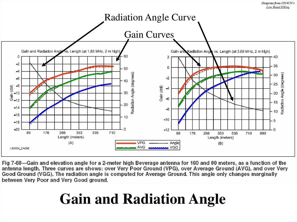
46. Ground Quality
• The better the ground, the lower the output• Ground quality has little impact on radiation
angle
• The poorer the ground, the less pronounced the
nulls between the different lobes
• Directivity remains almost constant
• Beverage does not work well over salt water
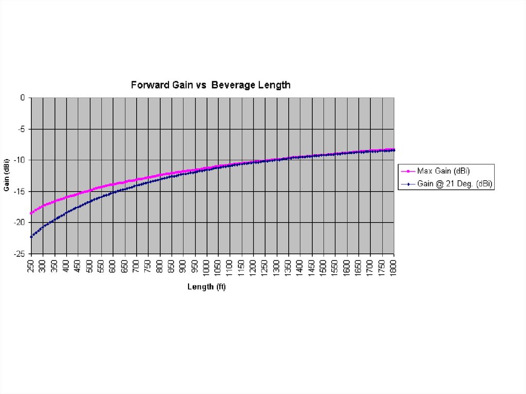
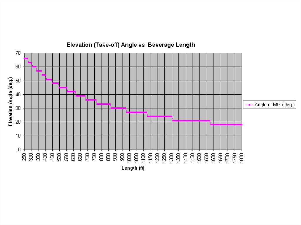
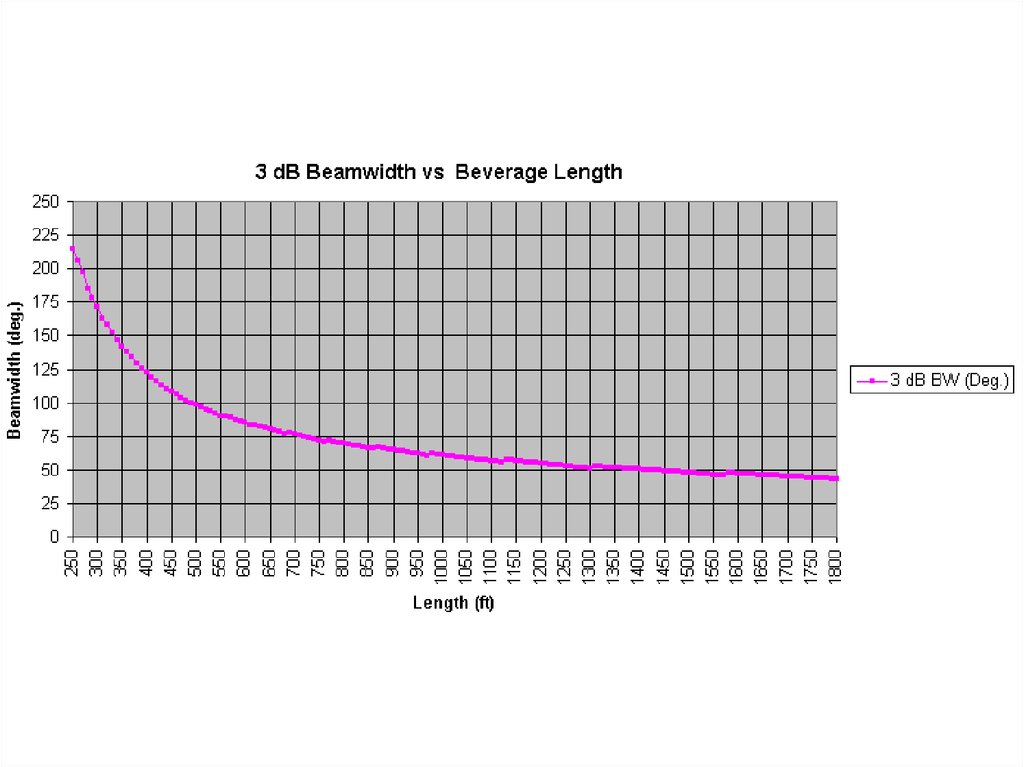
47.
Diagram from ON4UN’sLow Band DXing
Radiation Angle Curve
Gain Curves
Gain and Radiation Angle
48. Wire
• Inefficient antenna anyway, so size not criticalas long as it is physically strong enough
• Insulated, not insulated – doesn’t matter
• Pre-stretch soft-drawn copper wire
• Copper-clad and aluminum wire also okay
49. Theoretical Surge Impedance
Z = 138 log 4hd
Where:
h = height of wire
d = wire diameter (in same units)
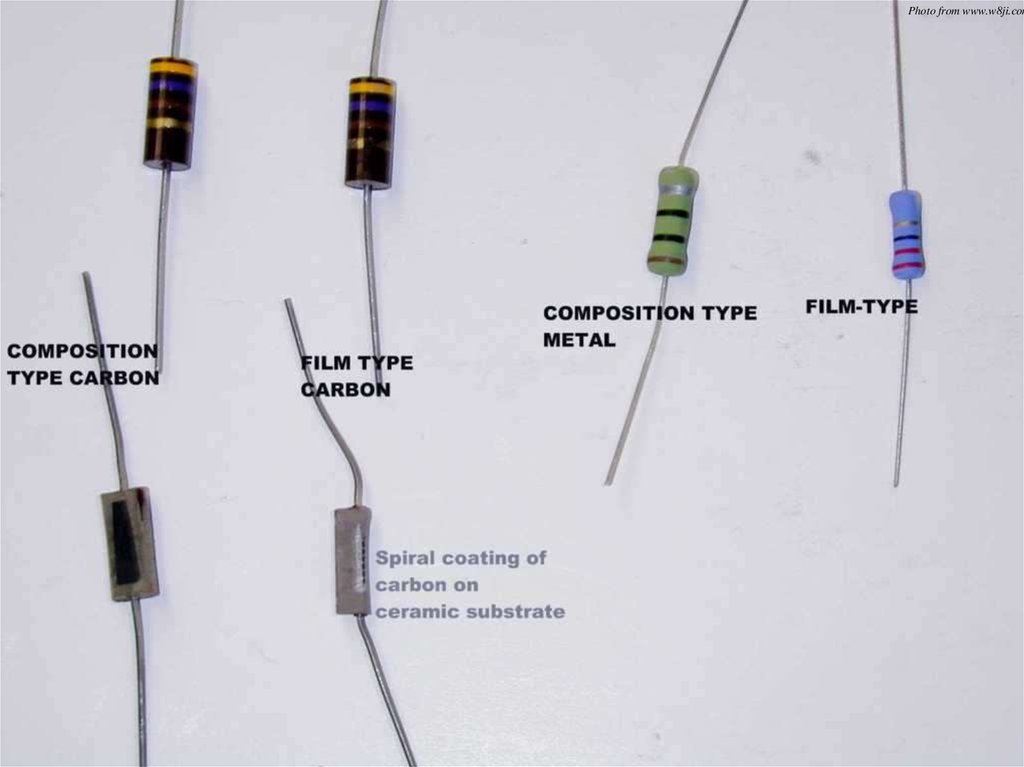
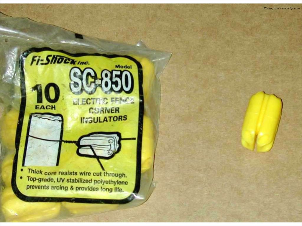
50. Termination Resistor
Photo from ON4UN’sLow Band DXing
Termination Resistor
• Should be non-inductive
• Antenna will pick up TX power and
lightning surges, so use 2 watt resistor
• Metal Film and Carbon Film cannot handle
surges
• Use Carbon Composition
• Use a Spark Gap
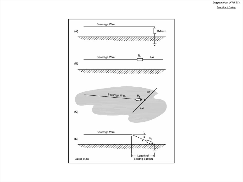
51.
Photo from www.w8ji.com52.
Diagram from ON4UN’sLow Band DXing
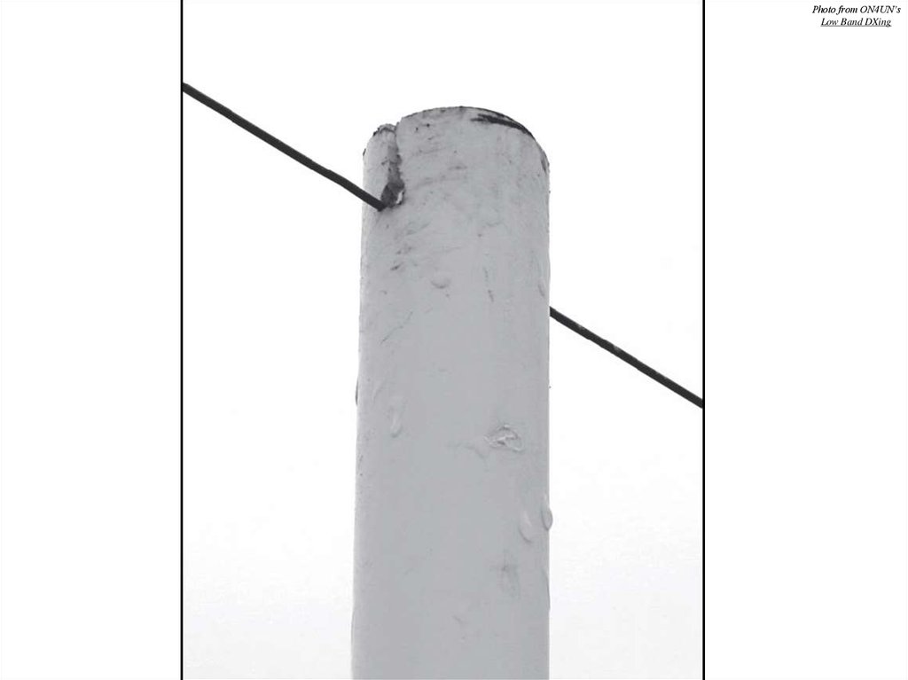
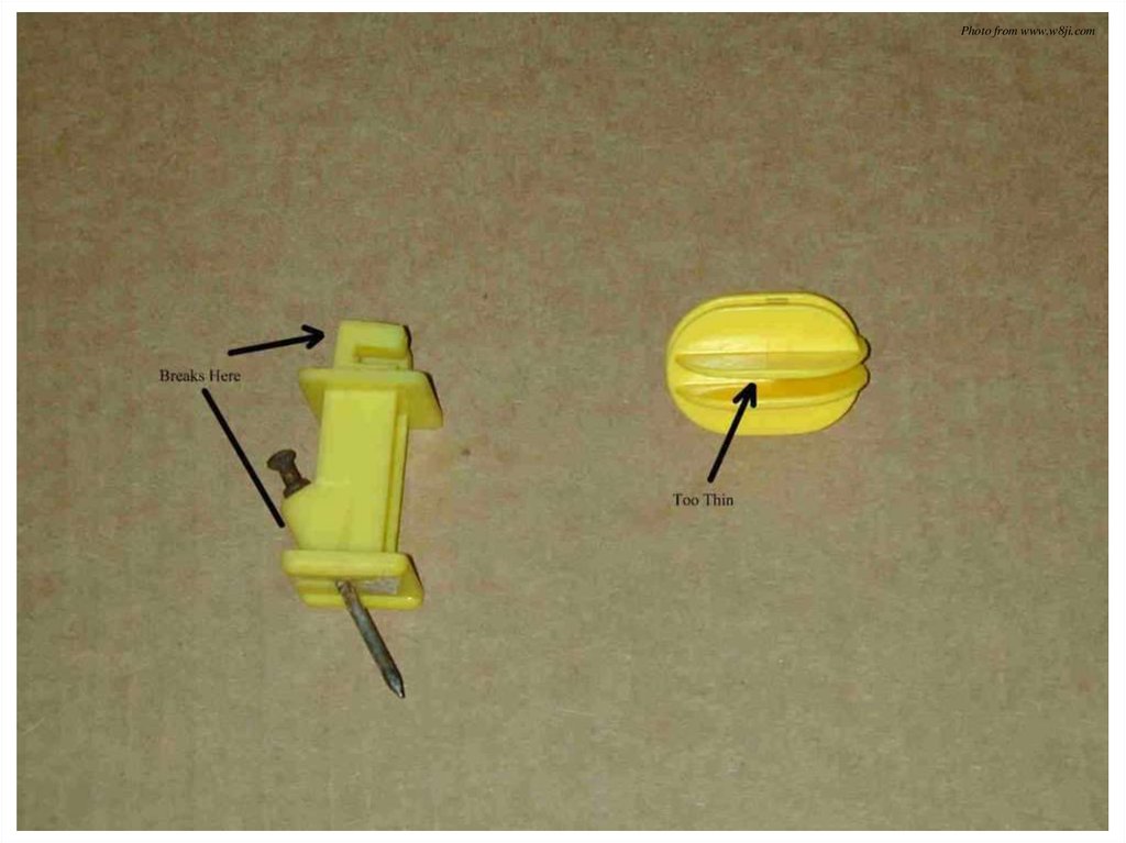
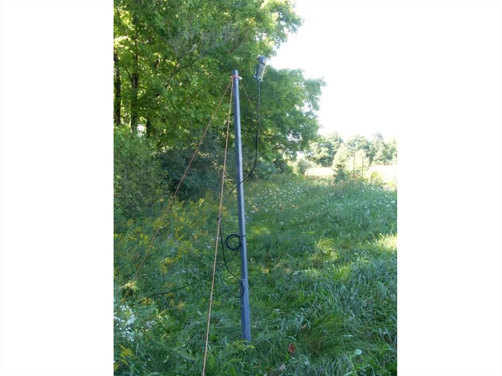
53. Supports
• Metal, non-metallic – doesn’t matter as long asantenna is insulated
• Poles, fence posts, trees, sheds, misbehaving
children – whatever is available
• Do not wrap wire around an insulator
• Try to keep it straight and level, but minor
variations are okay
54.
55.
Photo from ON4UN’sLow Band DXing
56.
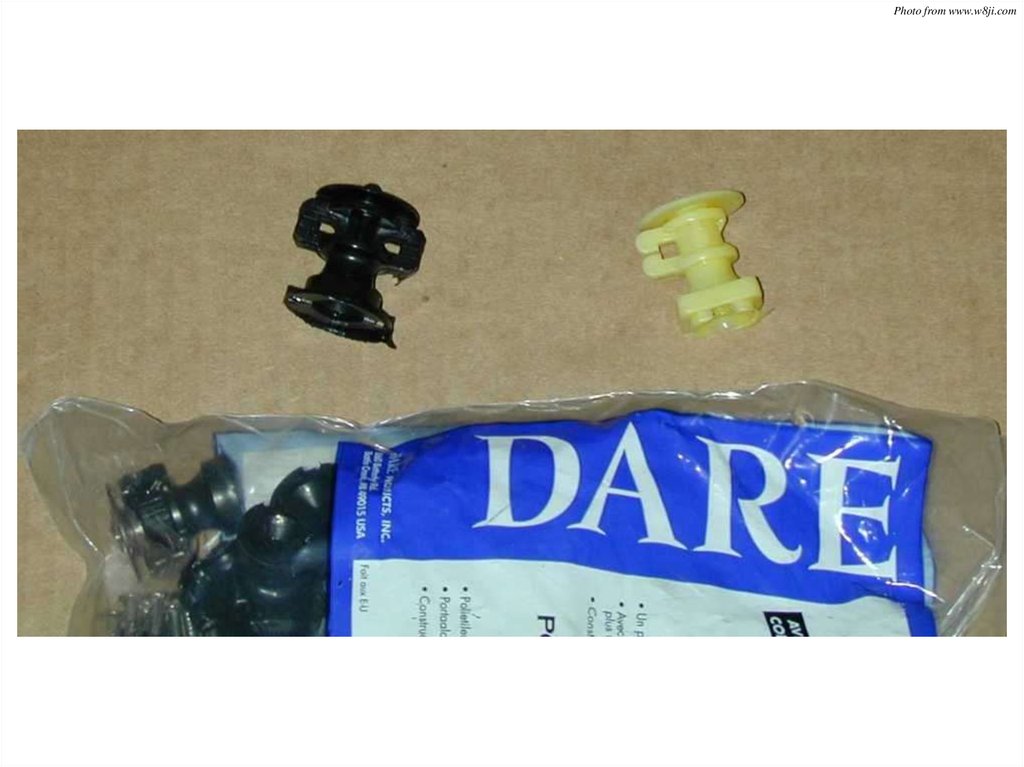
Photo from www.w8ji.com57.
Photo from www.w8ji.com58.
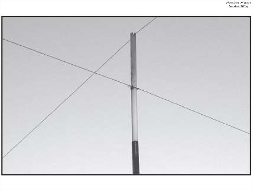
Photo from www.w8ji.com59. Parallel and Crossing Beverages
• Separate parallel Beverages by distanceequal to their height above ground
• Separate by at least 10 cm when crossing
• Do not run close to parallel conductors
(fences, telephone poles etc.)
60.
Photo from ON4UN’sLow Band DXing
61.
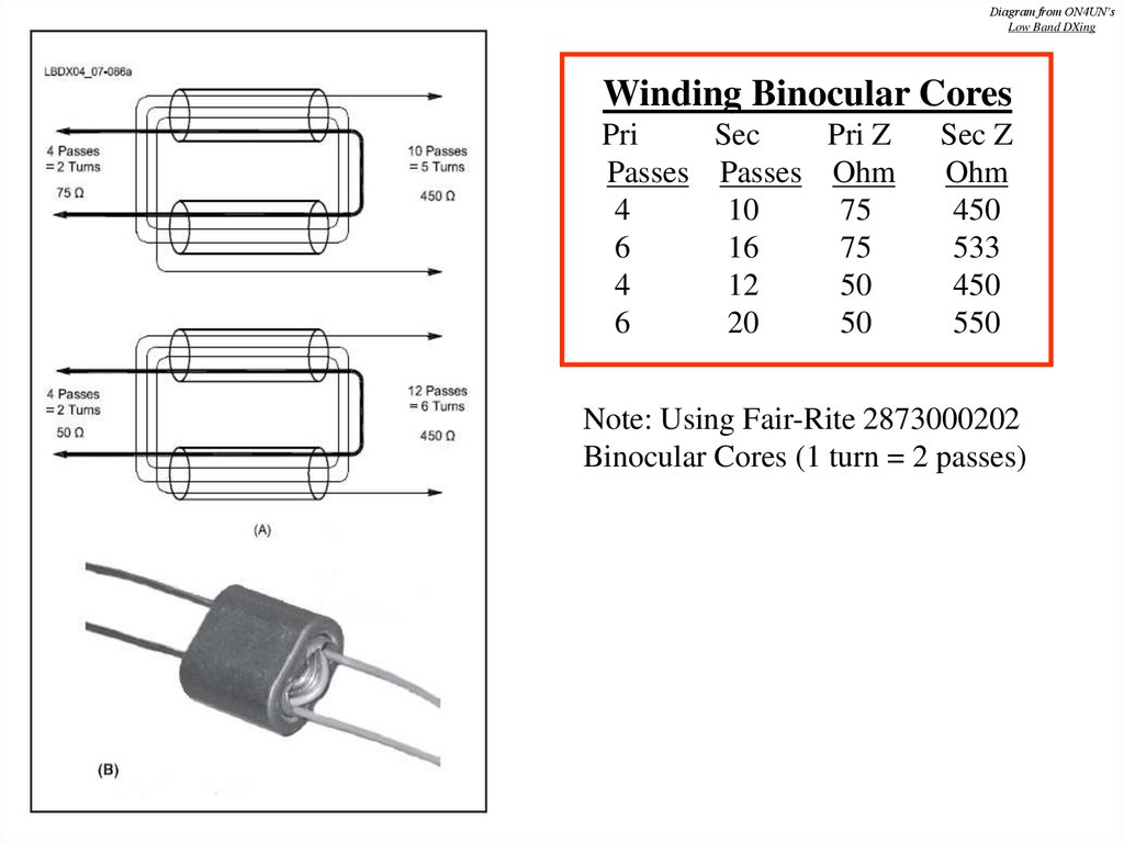
62. Matching the Beverage Antenna
• Several different core material/turnscombinations available
• Separate primary/secondary windings advisable
• I prefer Type 73 Binocular Cores as
recommended by W8JI
63.
Diagram from ON4UN’sLow Band DXing
Winding Binocular Cores
Pri
Sec
Pri Z
Passes Passes Ohm
4
10
75
6
16
75
4
12
50
6
20
50
Sec Z
Ohm
450
533
450
550
Note: Using Fair-Rite 2873000202
Binocular Cores (1 turn = 2 passes)
64. Coax
• Can use 50 or 75 Ohm cable• I prefer 75 Ohm cable
–
–
–
–
Works very well (ensure it is good quality cable)
Cheap!
Easy to attach connectors in the field
Easily identifiable as part of RX system – will not
accidentally transmit into it
– Did I mention that it is cheap?
65. Grounds
• One 8-foot ground rod may suffice• Will probably need two or more to stabilize the
ground system
• Can supplement it with a number of short radials
to form capacitance hat to earth
• On coax end of antenna, do not ground the coax
braid
• Ensure the coax braid ground is no closer than 5
meters to the ground attached to the transformer
66.
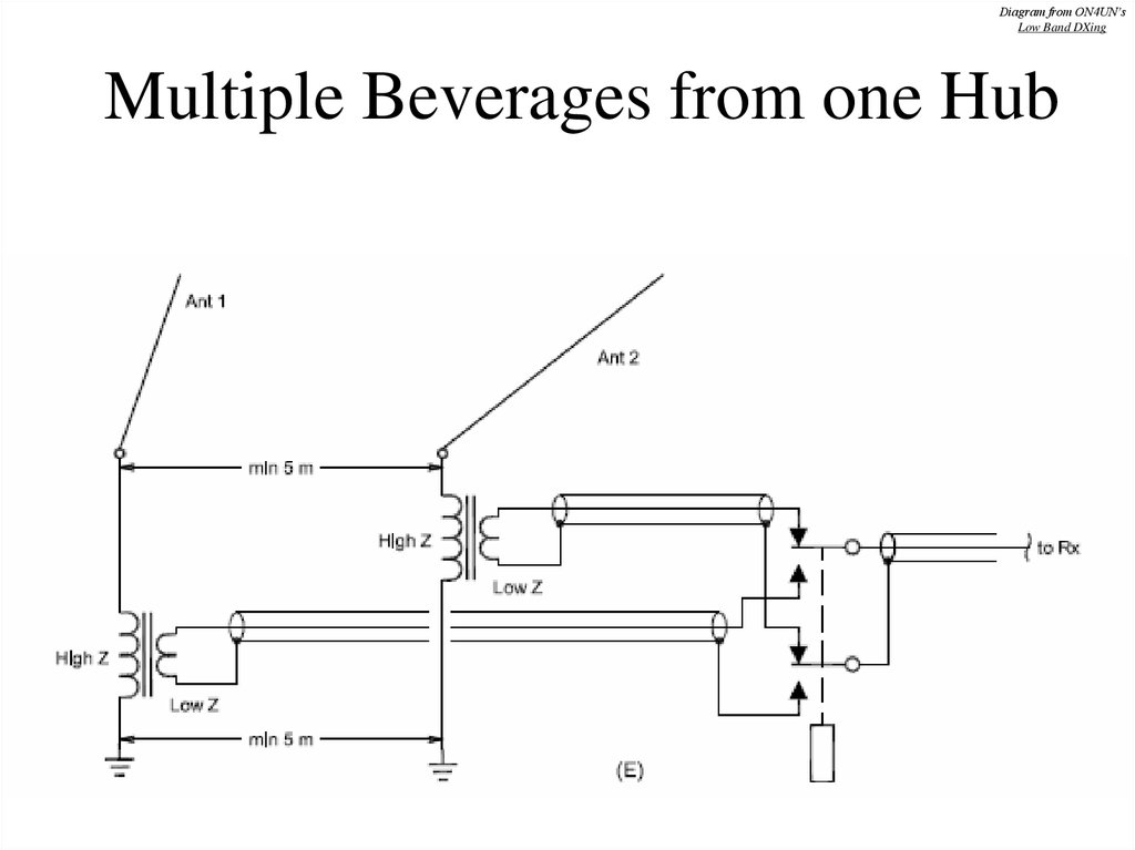
Diagram from ON4UN’sLow Band DXing
Multiple Beverages from one Hub
67.
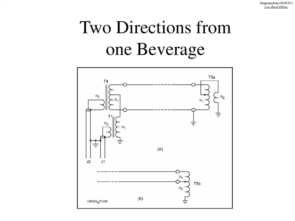
Diagram from ON4UN’sLow Band DXing
Two Directions from
one Beverage
68.
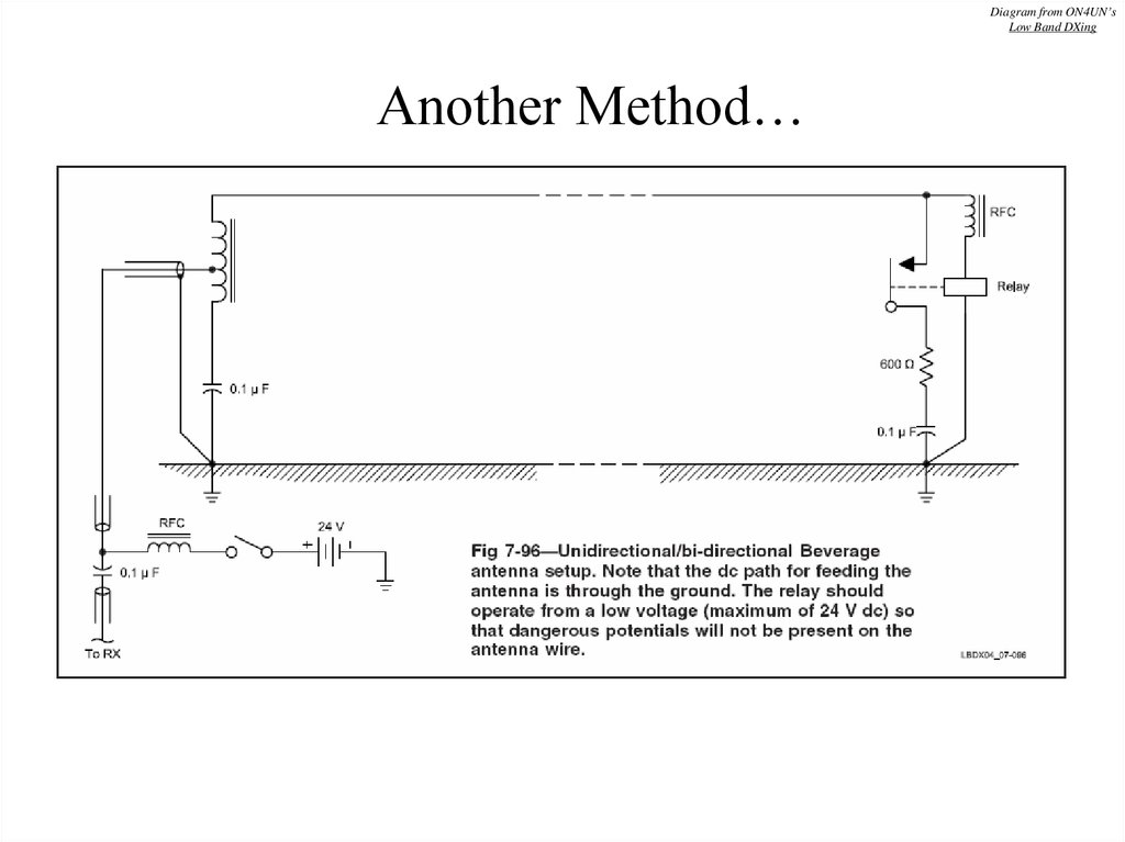
Diagram from ON4UN’sLow Band DXing
Another Method…
69. Phasing Beverage Antennas
• To improve directivity without using longantennas, can phase individual Beverages
• Two methods:
– Broadside
– End-Fire (or Staggered)
• Each has its own advantages
70. Broadside Phasing
• Narrows frontal lobe• Front/Back remains
the same
• Fed in phase
• Multiband
• Require wide spacing
• 0.5 wl spacing good
• 0.67 wl excellent!
To RX
Beverage
Coax
Splitter
0.5 to 0.67 wavelength
Coax
Beverage
RX Direction
71. End-Fire Phasing
Diagram from ON4UN’sLow Band DXing
End-Fire Phasing
• Greatly improves
Front/Back directivity
• Front lobe remains
much the same
• Spacing 5 meters
• Stagger NMT 0.5 wl
• 20 m for 40 – 160m ant
• 30 m if only 80 – 160m
72.
Photo from ON4UN’sLow Band DXing
73.
Diagrams from ON4UN’sLow Band DXing
• Broadside Phasing
• End-Fire Phasing
74. Crossfire Phasing
Diagram from ON4UN’sLow Band DXing
Crossfire Phasing
• Simple end-fire feed
system developed by W8JI
• Usable over several octaves
• Termination value = twice
that of single Bev
• 16:1 matching transformer
used (900 Ohms)
• (X – S)/2 = Y2
• Y1 = X – Y2
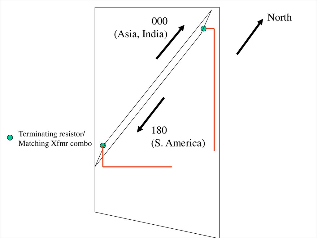
75. Beverage Antennas at VO1NO/VE3
5 acres near Merrickville
Dimensions ~ 650 x 320 feet
8 directions using end-fire phased Beverages
Control Box in shack, with 3 switchboxes in field
76.
77.
78.
79.
000(Asia, India)
Terminating resistor/
Matching Xfmr combo
180
(S. America)
North
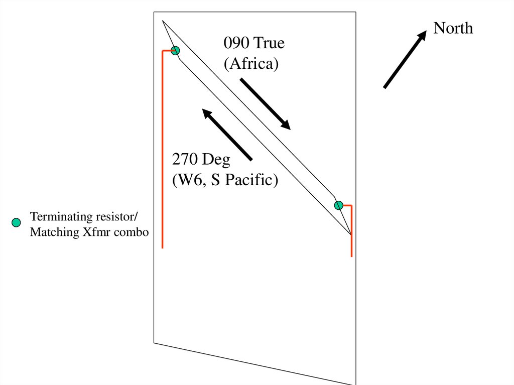
80.
090 True(Africa)
270 Deg
(W6, S Pacific)
Terminating resistor/
Matching Xfmr combo
North
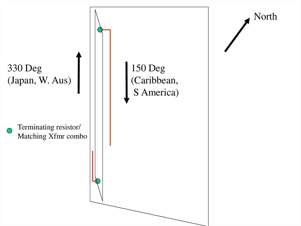
81.
North330 Deg
(Japan, W. Aus)
Terminating resistor/
Matching Xfmr combo
150 Deg
(Caribbean,
S America)
82.
North225
(W. Coast, NZ)
Terminating resistor/
Matching Xfmr combo
Signal combiner
045
(Europe, N. Africa)
83.
NorthTerminating resistor/
Matching Xfmr combo
84. Property too small?
Diagram from ON4UN’sLow Band DXing
Property too small?
• Try a BOG (Beverage On Ground)
–
–
–
–
–
Termination ~ 200 to 300 Ohms
Need a 4:1 matching transformer
Use ferrite beads to decouple feedline
May require a preamp
Beverage’s first antennas were laid on the ground
85.
Example of an urban beverage installation86. For more Information…
• The “Bible”!!• Also check the website of
Tom Rauch, W8JI:
– http://www.w8ji.com
• Try the Topband Reflector as
well:
– http://lists.contesting.com/_top
band/
• Joseph Carr’s book also has
lots of good stuff.