


")


 software
Similar presentations:


Welcome to Technical Training Induction
1. Welcome to Technical Training Induction
2. OBJECTIVE
By the end of this course you will have completed the followingModules to an acceptable level assessed by the trainer
• Laser Safety
• Electronic Imaging
• Safe Lifting
• Laptop Skills
• Electrical competence
• Electro Static Discharge
• Basic Xerography
• Colour Theory
• Toner Types
• Customer Handling Skills
3. Basic Xerography
4.
Agenda• Course Objective
• The Xerographic Process
• Charging
• Photoreceptors
• Charging Devices
• Exposing
• Development
• Transfer
• Fusing
• Cleaning
• Questions & Answers
4
5.
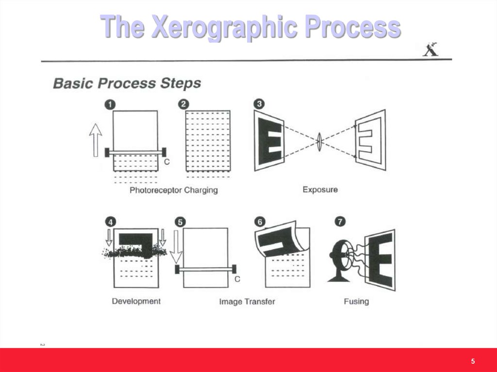
The Xerographic Process5
6.
ChargingPreparing the photoreceptor for accepting the image
6
7.
78.
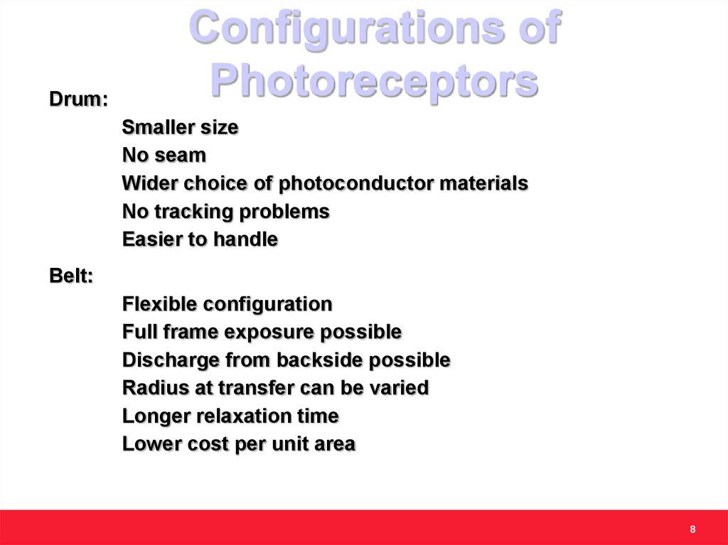
Drum:Configurations of
Photoreceptors
Smaller size
No seam
Wider choice of photoconductor materials
No tracking problems
Easier to handle
Belt:
Flexible configuration
Full frame exposure possible
Discharge from backside possible
Radius at transfer can be varied
Longer relaxation time
Lower cost per unit area
8
9.
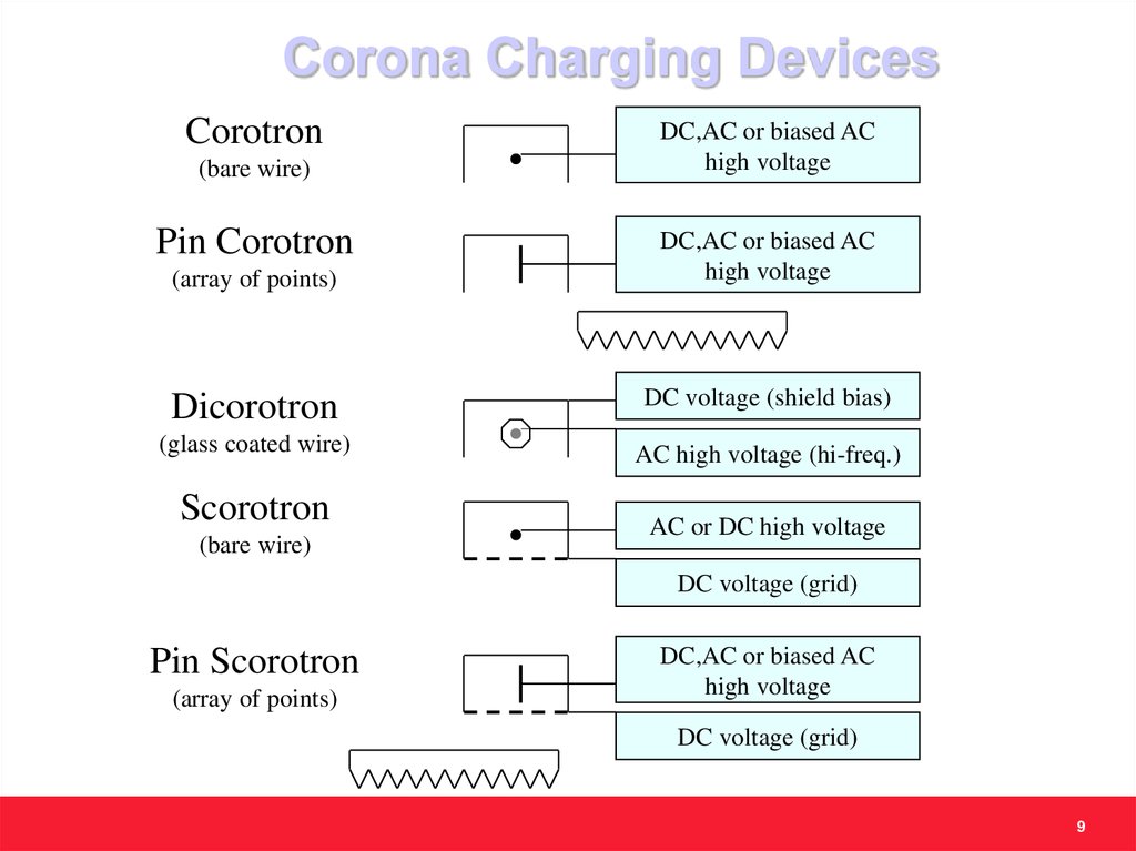
Corona Charging DevicesCorotron
(bare wire)
Pin Corotron
(array of points)
DC,AC or biased AC
high voltage
DC,AC or biased AC
high voltage
Dicorotron
DC voltage (shield bias)
(glass coated wire)
AC high voltage (hi-freq.)
Scorotron
(bare wire)
AC or DC high voltage
DC voltage (grid)
Pin Scorotron
(array of points)
DC,AC or biased AC
high voltage
DC voltage (grid)
9
10.
Bias Charging Roll10
11.
Bias Charging Roll – Pros & consAdvantages:
Size
Low Ozone emissions
Lower power requirements
Disadvantages:
Limited extensibility to higher process speeds
Uniform charging requires AC
Adds to power supply
AC decreases conventional PR life
11
12.
ExposingCapturing the latent image on the photoreceptor
12
13.
Imaging Devices13
14.
Photoreceptor Discharge MechanismPhoton
- - - - - -
- - - - - -
CTL
CTL
CGL
CGL
Substrate
Substrate
-+
(2)
(1)
- - - - - CTL
- - - -
-
CTL
-+
CGL
CGL
Substrate
Substrate
(3)
(4)
14
15.
DevelopmentToning the latent image
15
16.
DevelopmentTwo Main Schemes:
• Single Component Development (SCD)
Toner only
• Two Component Development (TCD)
Developer (Toner & Carrier)
• Materials
Toner size 5 to 15 mm
Carrier size 35 to 150 mm
Theory of Operation:
• Electric charge is created on the toner via friction (SCD) or
interaction with carrier (TCD)
• Charged toner is deposited on the latent image on PR
16
17.
Background remainscharged
17
18.
1819.
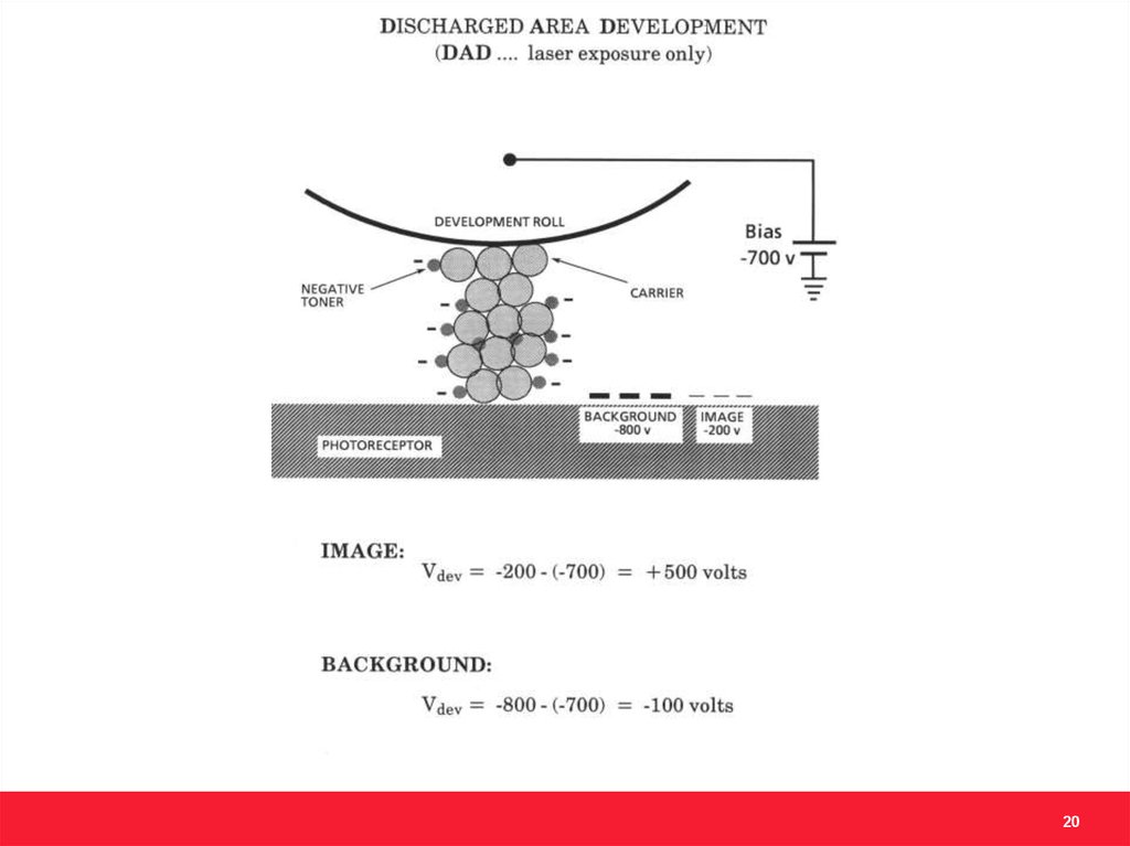
Why DAD?Only the area that needs to be developed is
exposed and discharged
• Lower exposure power requirements
• Lasers / LED bars vs. exposure lamps
• Less optical fatigue on photoreceptor
• Extends life
19
20.
2021.
Examples:Hodaka, A297, 1012, etc.
Several low-end printers
21
22.
Common Two ComponentDevelopment Techniques
22
23.
Magnetic Brush DevelopmentRoll Trim
S
N
Develop
N
Pick up
S
N
Sleeve
Roughened or ribbed
Magnets
The conductivity of the carrier determines whether the mag
brush is insulative, semi-conductive, or conductive
23
24.
Examples:Lakes Family,
Tigris, Nuvera
24
25.
TransferMoving the toned image to paper
25
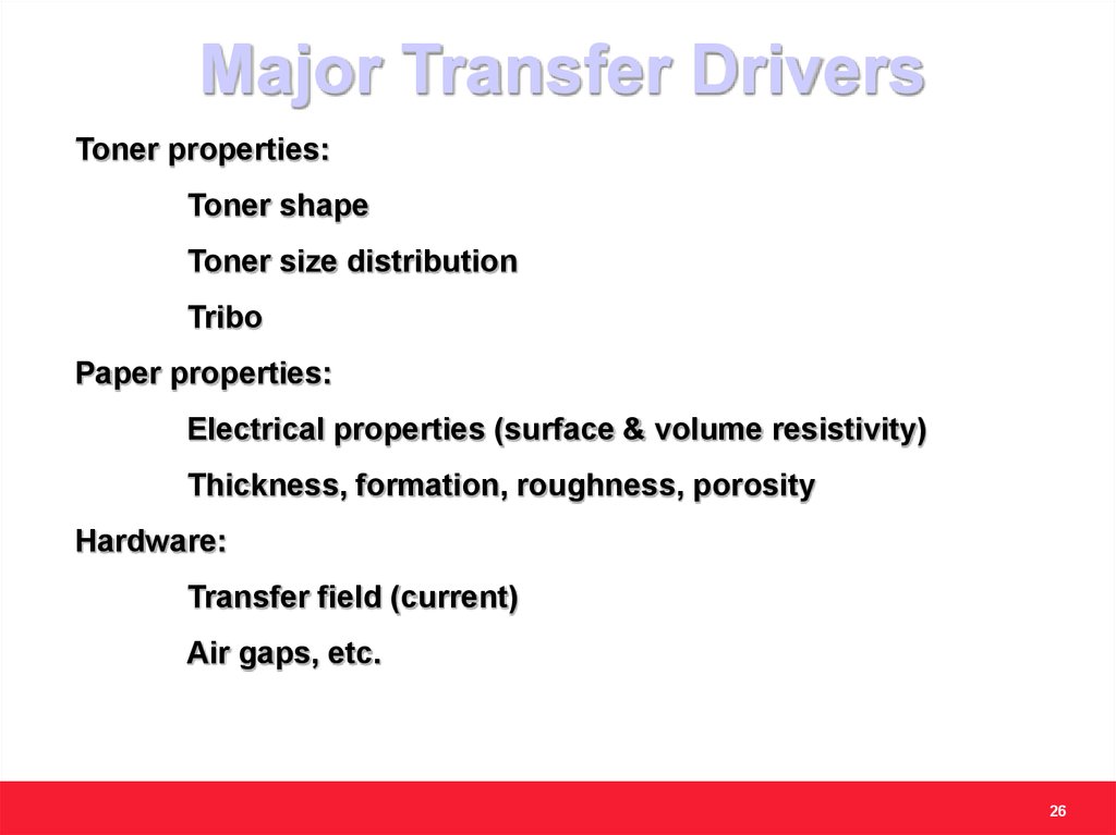
26.
Major Transfer DriversToner properties:
Toner shape
Toner size distribution
Tribo
Paper properties:
Electrical properties (surface & volume resistivity)
Thickness, formation, roughness, porosity
Hardware:
Transfer field (current)
Air gaps, etc.
26
27.
Common TransferSystems
• Corona
• Biased Transfer Roll
• Transfer Belt
• Charged Transfer Roll (CTR)
• Intermediate Transfer Belt
• Acoustic Transfer Assist (ATA)
27
28.
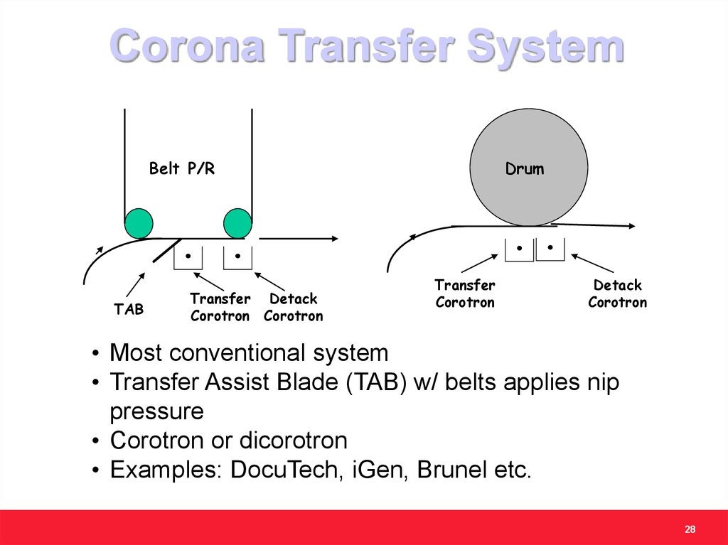
Corona Transfer SystemBelt P/R
TAB
Transfer Detack
Corotron Corotron
Drum
Transfer
Corotron
Detack
Corotron
• Most conventional system
• Transfer Assist Blade (TAB) w/ belts applies nip
pressure
• Corotron or dicorotron
• Examples: DocuTech, iGen, Brunel etc.
28
29.
Corona System: Theory ofOperation
++++++++
Idy
o
V
Transfer
Corotron
o
Detack
Idy
• Fields created by charge density deposited onto paper by
transfer corotron
• After transfer of toner, charge on the paper neutralized by
detack corotron
29
30.
Biased Transfer RollSystem
Belt P/R
BTR
Drum
Detack
BTR
Detack
• Used in most desktop printers
• Conformable nip
• Low ozone and high current efficiency
30
31.
BTR system: Theory ofOperation
P/R Drum
BTR
Fields created by charge density on the bias roll
(due to the BTR potential) and by charge deposited onto
paper from the BTR.
31
32.
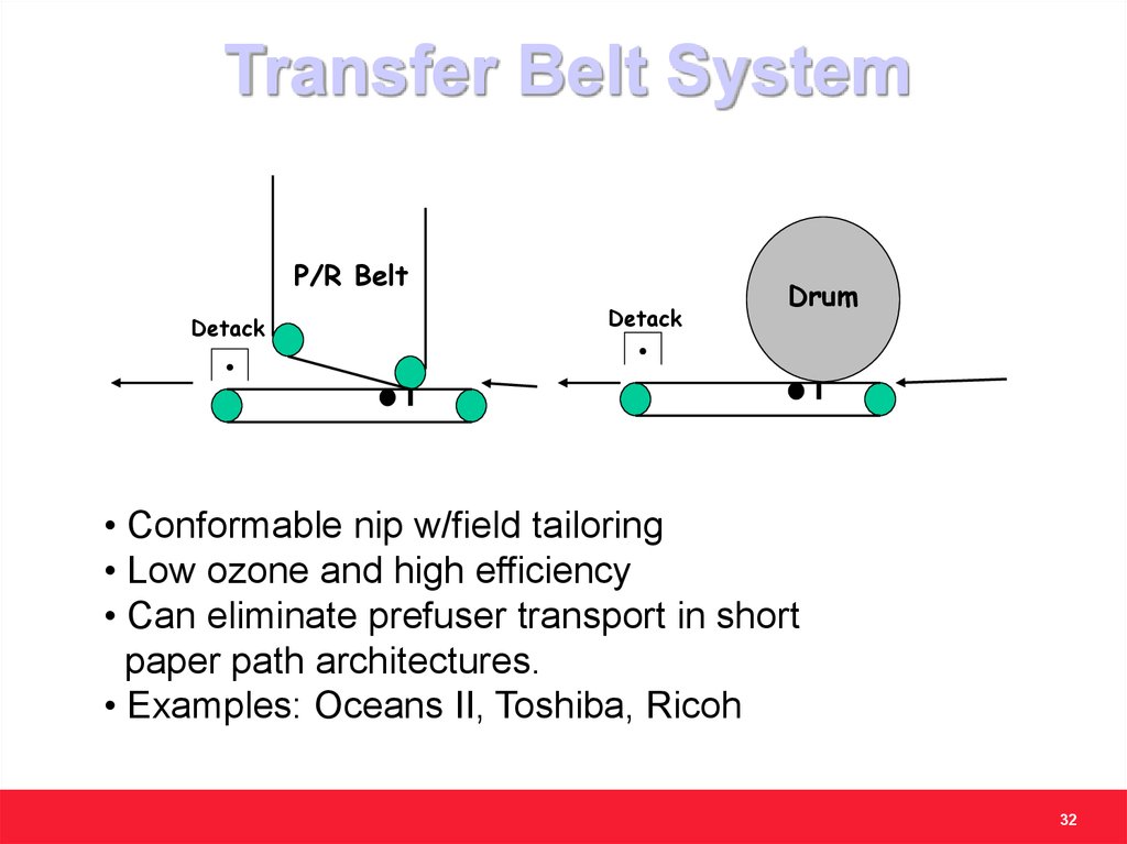
Transfer Belt SystemP/R Belt
Detack
Detack
Drum
• Conformable nip w/field tailoring
• Low ozone and high efficiency
• Can eliminate prefuser transport in short
paper path architectures.
• Examples: Oceans II, Toshiba, Ricoh
32
33.
CTR System.
Fuser
PR Drum
CTR Film
Rotary
Development
Unit
Example: Majestik family
• Full process color achieved by developing and transferring one
color at a time on to paper
• Cons
• Four passes per print - low productivity
• Limited substrate applicability
33
34.
Intermediate Belt TransferSystem
Intermediate
Transfer Belt
BTR
BTR
Paper
In
2nd
BTR
BTR
BTR
Paper
Out
Fuser
•System approach – build colors on intermediate belt
•Dual conformable nip transfers with BTR’s
•Low ozone and high current efficiency
•Examples: Sfida family, Imari-MF family, Ricoh
34
35.
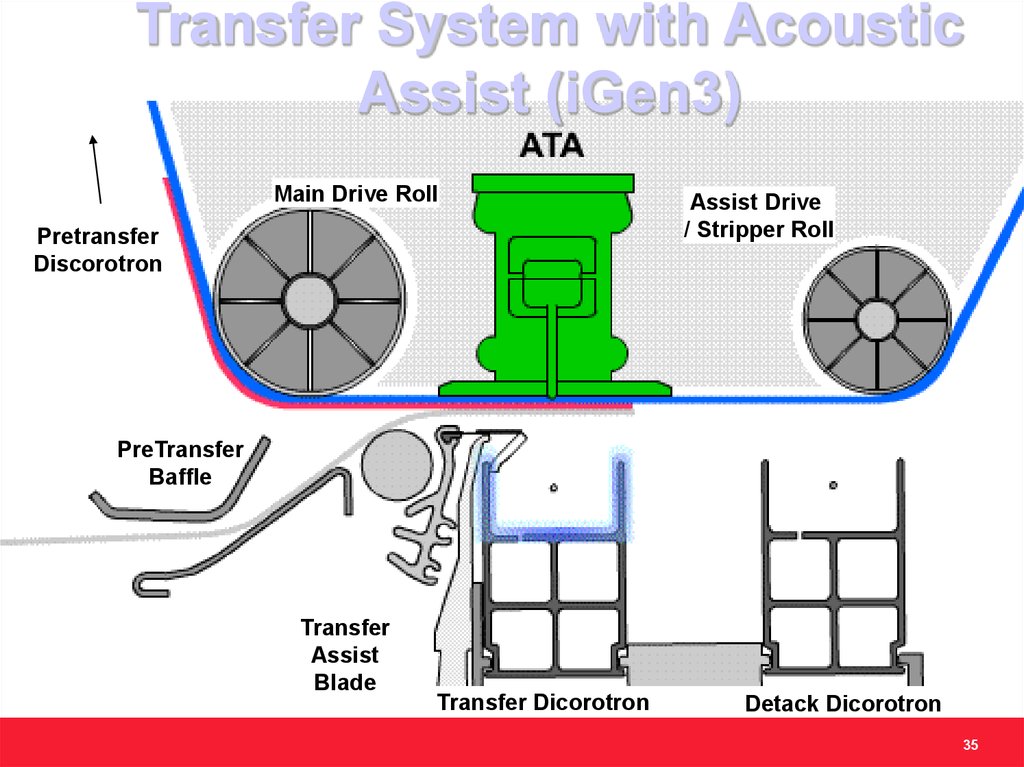
Transfer System with AcousticAssist (iGen3)
Main Drive Roll
Pretransfer
Discorotron
Assist Drive
/ Stripper Roll
PreTransfer
Baffle
Transfer
Assist
Blade
Transfer Dicorotron
Detack Dicorotron
35
36.
FusingFixing the image to paper
36
37. Common Fusing Techniques
e. g. Delphaxe. g. Fujitsu
e. g. Xeikon
e. g. Xerox and
many others
37
38.
Most-Common Fuser Type - Roll3 distinct types—all based on a roll pair comprised
of “hard” and “soft” rolls
Pressure
Stripping
assist
Ttoner(top)
Ttoner(bottom)
Formation of nip (dwell)
requires at least one
rubberized roll
Dwell
38
39.
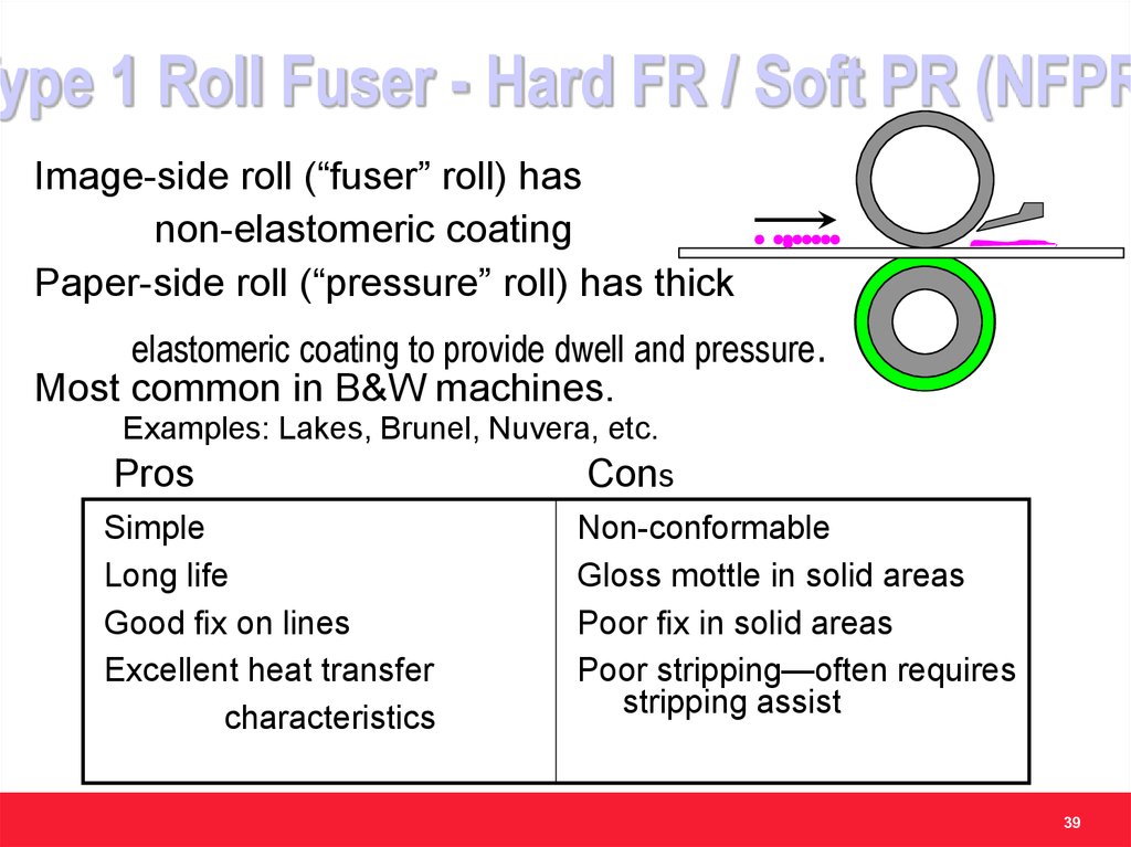
Type 1 Roll Fuser - Hard FR / Soft PR (NFPRImage-side roll (“fuser” roll) has
non-elastomeric coating
Paper-side roll (“pressure” roll) has thick
elastomeric coating to provide dwell and pressure.
Most common in B&W machines.
Examples: Lakes, Brunel, Nuvera, etc.
Pros
Cons
Simple
Long life
Good fix on lines
Excellent heat transfer
characteristics
Non-conformable
Gloss mottle in solid areas
Poor fix in solid areas
Poor stripping—often requires
stripping assist
39
40.
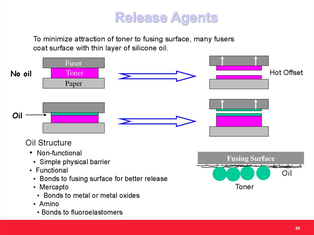
Release AgentsTo minimize attraction of toner to fusing surface, many fusers
coat surface with thin layer of silicone oil.
No oil
Fuser
Toner
Paper
Hot Offset
Oil
Oil Structure
• Non-functional
• Simple physical barrier
• Functional
• Bonds to fusing surface for better release
• Mercapto
• Bonds to metal or metal oxides
• Amino
• Bonds to fluoroelastomers
Fusing Surface
Oil
Toner
40
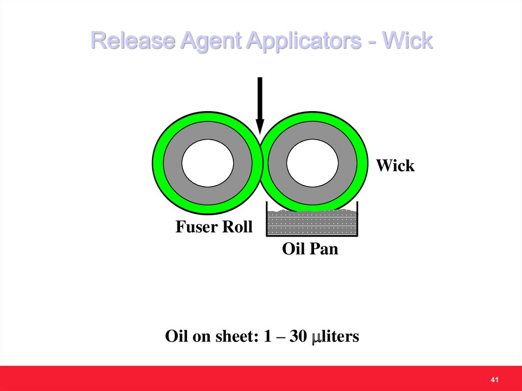
41.
Release Agent Applicators - WickWick
Fuser Roll
Oil Pan
Oil on sheet: 1 – 30 mliters
41
42.
Release Agent Applicators - Donor RollFuser Roll
Donor Roll
Metering Blade
Pick-up Roll
Oil Pan
Pressure Roll
Oil on sheet: 1 – 10 mliters
42
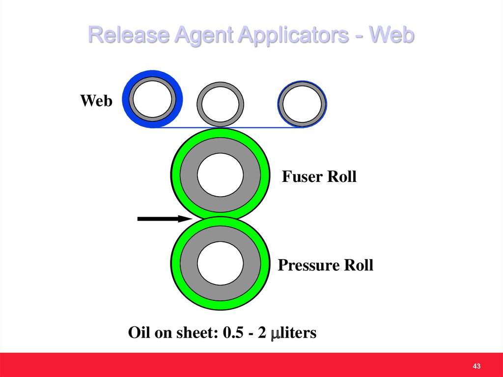
43.
Release Agent Applicators - WebWeb
Fuser Roll
Pressure Roll
Oil on sheet: 0.5 - 2 mliters
43
44.
Release Agent Issues• Undesirable feel
• Inability to write on the print or to stick
“Post-it” notes
• Impact on projection efficiency
• Additional hardware, service, and
consumables cost
• The trend is to use wax in the toner
formulation to avoid the above stated issues
44
45.
StrippingStripping aids are required in non-stripping
fusers for robustness.
Stripping Finger
Issue: Unacceptable print
quality due to stripping finger
marks
Air knife
Stripper
Issue: cost of parts and air
supply
45
46. Imari-MF Family (Free Belt Nip Fuser)
Fuser RollH/Roll
Pad
Paper
Loa
d
Belt
Pressure
Pad
Load
Belt
Guide
Guide
47.
EraseRemoving the charge from the photoreceptor
47
48.
Erase• Erase is the process of eliminating any
electric memory of the previous image from
the PR surface
• A combination of uniform light exposure and
uniform charge exposure is used
• Light exposure is provided by an exposure
lamp
• The remaining electric charge is neutralized
using a corona device
48
49.
CleaningRemoving the residues from the photoreceptor
49
50. Types of Residual Materials
TonerPaper Debris
Fibers
Fillers:
Talc, Kaolin (clays), etc.
Adhesives (e.g. ream wrapper glue, labels)
Carrier Beads
Machine Wear Debris
Airborne Fibers, Adhesives, Etc.
50
51. Methods of Cleaning Toner
Mechanical ForcesBlade
Multi – Blades
Mechanical Brush
Foam Roll
Web
Electrostatic Forces
Electrostatic Brush
Magnetic Forces
Magnetic Brush (a.k.a., mag brush)
51
52. Methods of Cleaning Other Residuals
Disturber BrushesPaper
fibers and debris
Films from toner additives
Comets from toner additives
Spots Blades
Spots
52
53.
CommonCleaning
Systems
53
54. Blade Cleaner
BladeCritical Parameters:
Blade Angle
Force
Examples: Majestik, Imari-MF, etc.
Photoreceptor
Cons:
Pros:
Simple Design P/R Wear
Random failures
Low Cost
Unsuitable for spherical toners
55. Mechanical Brush Cleaner
Flicker Barmaterial chosen for
tribo charging
of brush
Rotation
against p/r
high speed
Fiber Brush
non-conducting
P/R
Example: 9000 family
56. Magnetic Brush Cleaner
Electrostatic Detoning Rollhigher bias than mag brush
Examples: 1075 / 1090
++
V
N
S
Auger
S
Rotation
+V
N
N
Magnetic Brush
conductive carrier,
formed on shell rotating
around stationary
magnets
S
P/R
Pros: Effective cleaning
Cons: Cost and life
S
N
against p/r
low speed
57. Electrostatic Brush Cleaner
Detoning Air Flowmoderate flows
Auger
++
V
Flicker Bar
material chosen for
wear resistance
+V
Fiber Brush
conductive fiber
Rotation
against p/r
moderate
speed
P/R
Pros: Effective cleaning even for spherical toners
Cons: Cost
58. TONER
59.
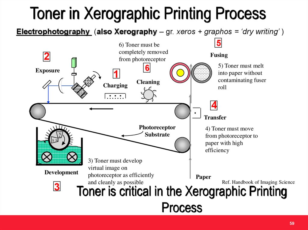
Toner in Xerographic Printing ProcessElectrophotography (also Xerography – gr. xeros + graphos = ‘dry writing’ )
6) Toner must be
completely removed
from photoreceptor
2
Exposure
1
Charging
5
Fusing
5) Toner must melt
into paper without
contaminating fuser
roll
6
Cleaning
4
Transfer
Photoreceptor
Substrate
N
S
S N
Development
3
3) Toner must develop
virtual image on
photoreceptor as efficiently
and cleanly as possible
4) Toner must move
from photoreceptor to
paper with high
efficiency
Paper
Ref. Handbook of Imaging Science
Toner is critical in the Xerographic Printing
Process
59
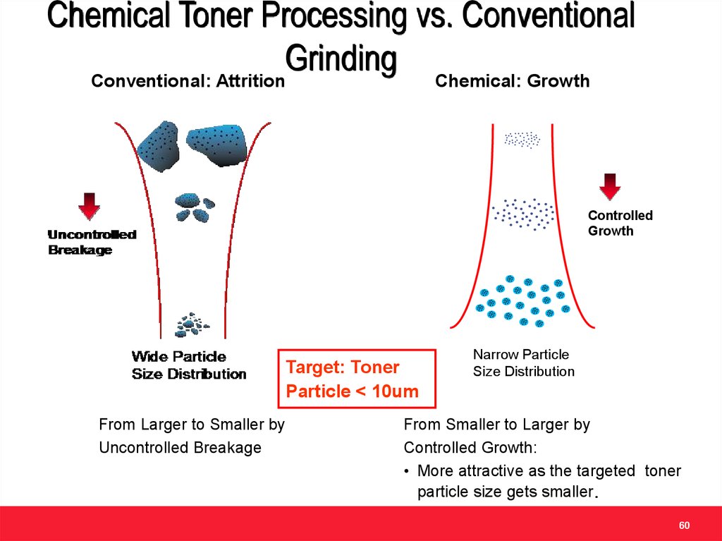
60.
Chemical Toner Processing vs. ConventionalGrinding
Conventional: Attrition
Chemical: Growth
Controlled
Growth
Target: Toner
Particle < 10um
From Larger to Smaller by
Uncontrolled Breakage
Narrow Particle
Size Distribution
From Smaller to Larger by
Controlled Growth:
• More attractive as the targeted toner
particle size gets smaller.
60
61.
Particles from Chemical/EA vs ConventionalToner
Processing
Conventional (old)
Chemical (new)
Wax
Latex
Pigment
1.1
1
Number Differential
1
Volume Differential
0.8
0.9
Number Differential
0.7
0.8
Normalized Count
Normalized Count
1.1
Volume Differential
0.9
0.6
0.5
0.4
0.3
0.7
0.6
0.5
0.4
0.3
0.2
0.2
0.1
0.1
0
1
10
Diameter (um)
100
0
1
10
100
Diameter (um)
• Irregular shape
• Rounded particles
• Wider distribution
• Uniform size distribution
• No structure control
• Enables toner structure
61
62.
Chemical vs. Conventional TonerProcessing
EA Toner Processing
Conventional Toner Processing
Polymerization
Monomer
& Initiator
Resin
Water
& Surfactant
Pigment
Emulsion
Polymerization
Pigment
Melt Mixing
Grinding/Jetting
Aggregation
Particle Formation
Washing/Drying
Classification
Coarse / Fine
Dry Mechanical Process
• high mechanical energy for grinding
• very sensitive to particle size
• easy recycling
Additive Blending
& Packaging
Toner
Wet Chemical Process
• requires washing & drying
• low sensitivity to particle size
• less emissions
62