


 electronics
Similar presentations:

 Image Formation Processing")


")


MMSE MIMO detection : problem definition UMTS coexists with illegal GSM
1.
MMSE MIMO detection : problem definitionUMTS coexists with illegal GSM
Problem definition:
The GSM interference contributes to the cells
belonging to a neighbor sites and hence full MMSE via 6
antennas is not allowed because of the limited interNodeB interface throughput (10Mbps)
GSM
interference
e
rfac
BTS
inte
UE
ps
Mb
10
10
Mb
ps
int
er f
ace
BTS
BTS
2.
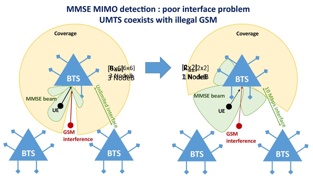
MMSE MIMO detection : poor interface problemUMTS coexists with illegal GSM
Coverage
Coverage
[6x6]
3 NodeB
BTS
[2x2]
1 NodeB
BTS
MMSE beam
e
rfac
nte
ps i
e
rfac
inte
UE
GSM
interference
BTS
Mb
ited
lim
UE
10
Un
MMSE beam
GSM
interference
BTS
BTS
BTS
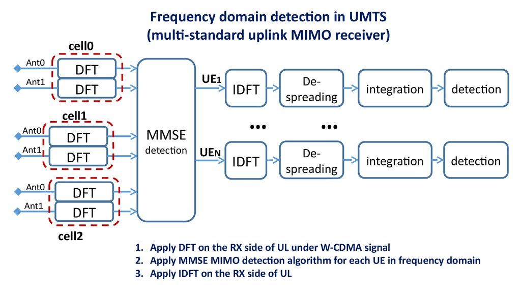
3.
cell0Ant0
Ant1
Frequency domain detection in UMTS
(multi-standard uplink MIMO receiver)
DFT
DFT
UE1
…
cell1
Ant0
Ant1
Ant0
Ant1
DFT
DFT
MMSE
detection
IDFT
UEN
IDFT
Despreading
integration
detection
integration
detection
…
Despreading
DFT
DFT
cell2
1. Apply DFT on the RX side of UL under W-CDMA signal
2. Apply MMSE MIMO detection algorithm for each UE in frequency domain
3. Apply IDFT on the RX side of UL
4.
Frequency domain MMSE MIMO detectionFor each subcarrier the MMSE MIMO detection in 6 antennas UL case is based on
the equation:
,
(6x1) – weight vector, (6x6) – autocorrelation matrix of input signal, (6x1) – channel estimation
vector, (6x1) – input signal vector, (scalar complex value) - detected signal.
From the Sherman-Morrison formula can be derived:
(6x6) – interference plus noise matrix which is responsible for an interference suppression, i.e.
interference rejection combining (IRC), while (6x1) represents the direction to the user, i.e. maximum
ratio combining (MRC), - SINR (scalar value), is the N-of-users per cell.
5.
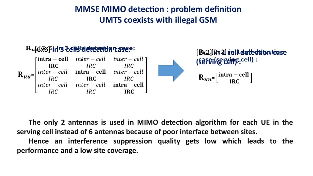
MMSE MIMO detection : problem definitionUMTS coexists with illegal GSM
[6x6] in 3 cells detection case:
=
[2x2] in 1 cell detection case
(serving cell) :
=
The only 2 antennas is used in MIMO detection algorithm for each UE in the
serving cell instead of 6 antennas because of poor interface between sites.
Hence an interference suppression quality gets low which leads to the
performance and a low site coverage.
6.
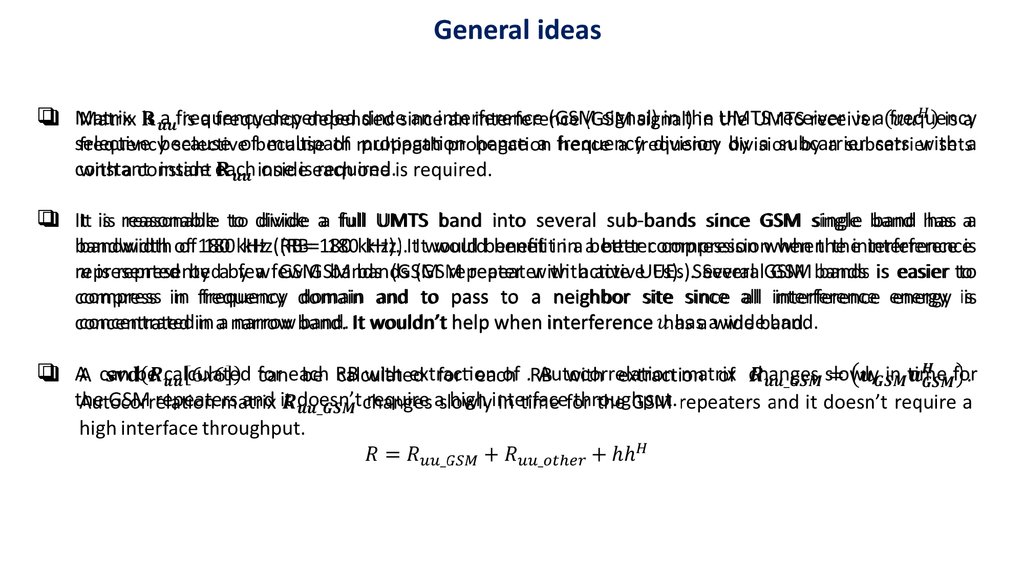
General ideasMatrix is a frequency depended since an interference (GSM signal) in the UMTS receiver is a frequency
selective because of multipath propagation hence a frequency division by a subcarrier sets with a
constant inside each one is required.
It is reasonable to divide a full UMTS band into several sub-bands since GSM single band has a
bandwidth of 180 kHz (RB= 180 kHz). It would benefit in a better compression when the interference is
represented by a few GSM bands (GSM repeater with active UEs). Several GSM bands is easier to
compress in frequency domain and to pass to a neighbor site since all interference energy is
concentrated in a narrow band. It wouldn’t help when interference has a wide band.
A can be calculated for each RB with extraction of . Autocorrelation matrix changes slowly in time for
the GSM repeaters and it doesn’t require a high interface throughput.
7.
Method 1 : frequency domain compressioncompromise: max power/max correlation/max compression
GSM interference is the main concern in the UMTS receiver. Hence in the neighbor NodeB the only RBs
inside each antenna are interesting which have the features:
1.
2.
3.
A high correlation coefficient of between the serving cell and the neighbor NodeB;
A high power of interference;
Instant correlation properties correspond to the pre-calculated matrix.
The RBs with at least one different feature from the list (1-3) are not considered for transmission to the
serving cell since it wouldn't increase a performance on the serving cell. Also another one feature is
desired:
4. If signals and are equal in conditions (1-3) then that one is preferable which has a less compression
noise power (that who closer to the approximation).
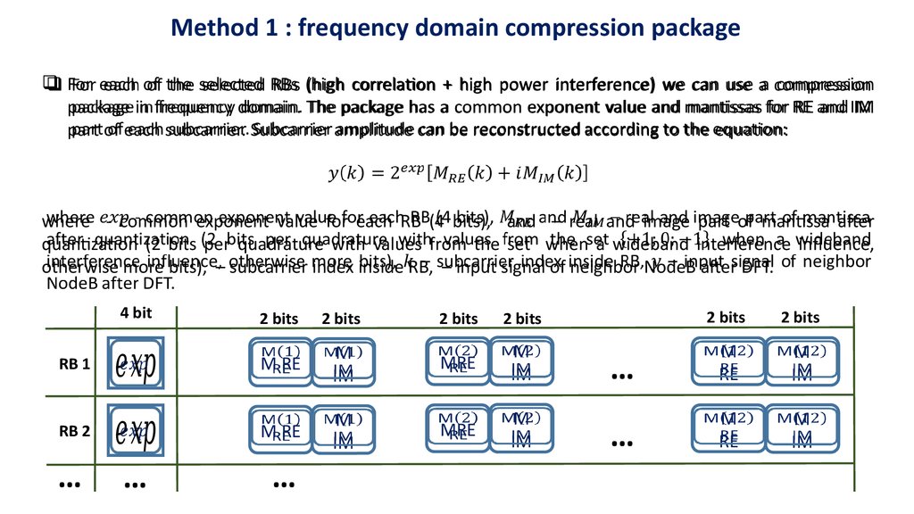
8.
Method 1 : frequency domain compression packageFor each of the selected RBs (high correlation + high power interference) we can use a compression
package in frequency domain. The package has a common exponent value and mantissas for RE and IM
part of each subcarrier. Subcarrier amplitude can be reconstructed according to the equation:
where - common exponent value for each RB (4 bits), and – real and image part of mantissa after
quantization (2 bits per quadrature with values from the set when a wideband interference influence,
otherwise more bits), – subcarrier index inside RB, – input signal of neighbor NodeB after DFT.
4 bit
2 bits
2 bits
2 bits
2 bits
2 bits
2 bits
MRE
M
IM
…
M
RE
M
IM
MRE
M
IM
…
M
RE
M
IM
RB 1
M RE
M
IM
RB 2
M RE
M
IM
…
…
…
9.
Method 1 : de-compression and detectionOn the serving cell the data from the neighbor NodeB are represented by a set of the selected
compressed RBs intended to suppress the GSM interference. For other RBs the multi-cell MMSE is less
efficient or inefficient at all and a common two antennas detection is considered.
Finally the number of antennas on the serving cell in MMSE detection process is different for each RB
and depend on the content of interface information. Detection matrixes examples:
[2x2] in 1 serving cell detection case
=
[6x6] in 3 cells detection case
=
[4x4] in 3 cells (4 antennas) detection case
=
[4x4] in 2 cells detection case
=
10.
Method 2 : Compressive sensing (introduction)Compressive sensing algorithm is applied under the neighbor NodeB signals :
,
where vector - compressed signal samples, vector – input signal samples, – a
transformation. A common MMSE solution is applicable in a common approximation
task and looks like:
For example, could be a DFT or a DCT, DWT and so on.
Example: in DFT (Method 1) under the occupied RBs the looks like:
- a set of used RBs indexes
11.
Method 2 : Compressive sensingThe vector of the GSM interference signal from the neighbor NodeB can be
decomposed into a weighted sum of orthogonal vectors in an orthogonal basis:
Orthogonal vectors set can be divided into 2 subspaces: first subspace is highly
correlated with the desired signal in the serving cell, another one – highly orthogonal to
the desired signal in the serving cell:
Each UE in a CDMA system uses a different code to modulate their signal. The
separation of the signals is made by correlation of the received signal with the locally
generated code of the desired UE. If the signal matches the desired UE code then the
correlation function will be high and the system can extract it. For other UEs with code
the correlation is close to zero.
12.
Method 2 : Compressive sensingThe set represents codes of UEs in the serving cell, the set represents all the other orthogonal codes .
The subspace of interference in the neighbor NodeB is the most interesting for transmission over the
interface since it wouldn’t be suppressed by a CDMA receiver because of high correlation with desired
UEs codes.
With the assumption that the residual interference signal lives in a known subspace which is
orthogonal to the signal of interest, the signals can be removed without violating the restricted
isometry principal (RIP) with respect to the signal of interest. And only an overall power of makes a
sense.
Desired signal basis is known both in the serving cell and can be calculated in the neighbor NodeB as
well. Thereby only the complex coefficients and have to be passed to the serving cell for 3cells MMSE
detection. Recovered signal in the serving cell can be written in the form:
where - random amplitudes generated with power condition: