


 mechanics
Similar presentations:


3D modelling busway
1.
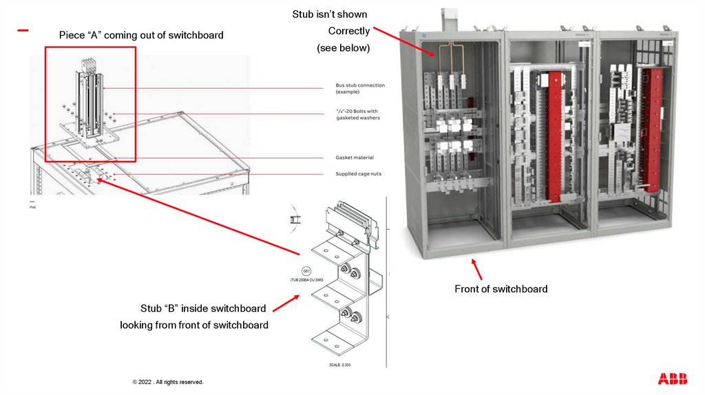
—Stub isn’t shown
Piece “A” coming out of switchboard
Correctly
(see below)
Front of switchboard
Stub “B” inside switchboard
looking from front of switchboard
© 2022 . All rights reserved.
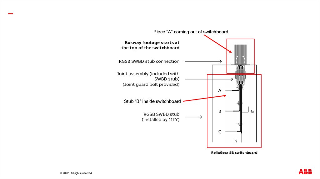
2.
—Piece “A” coming out of switchboard
Stub “B” inside switchboard
© 2022 . All rights reserved.
3.
—Should be regular piece of busway
Remove black plug outlets circled in red
See slide 5 for flat tee remarks
Plug-in unit should be rotated 180 degrees
Should be a box covering end of bus
Should have a joint with caps
And shields in here
© 2022 . All rights reserved.
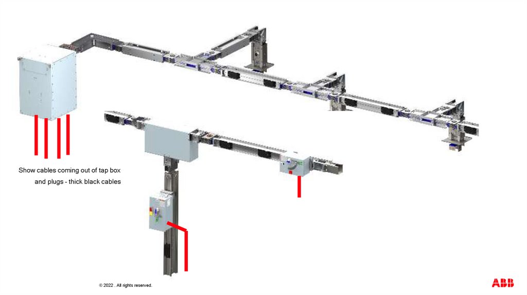
4.
—Show cables coming out of tap box
and plugs – thick black cables
© 2022 . All rights reserved.
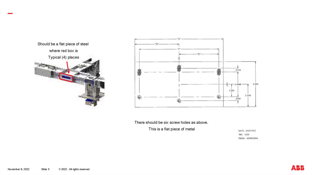
5.
—Should be a flat piece of steel
where red box is
Typical (4) places
There should be six screw holes as above.
This is a flat piece of metal
November 9, 2022
Slide 5
© 2022 . All rights reserved.
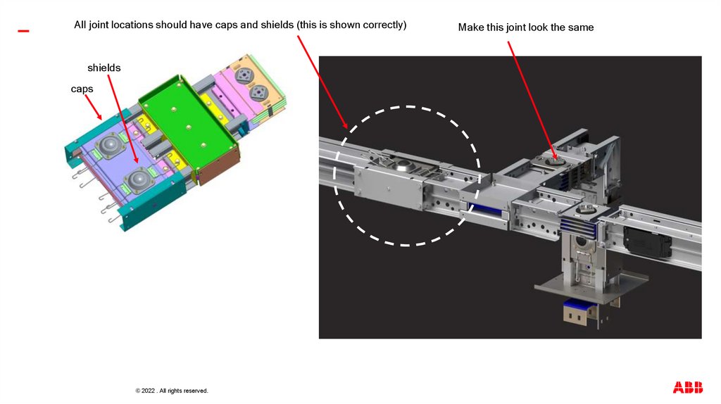
6.
—All joint locations should have caps and shields (this is shown correctly)
shields
caps
© 2022 . All rights reserved.
Make this joint look the same
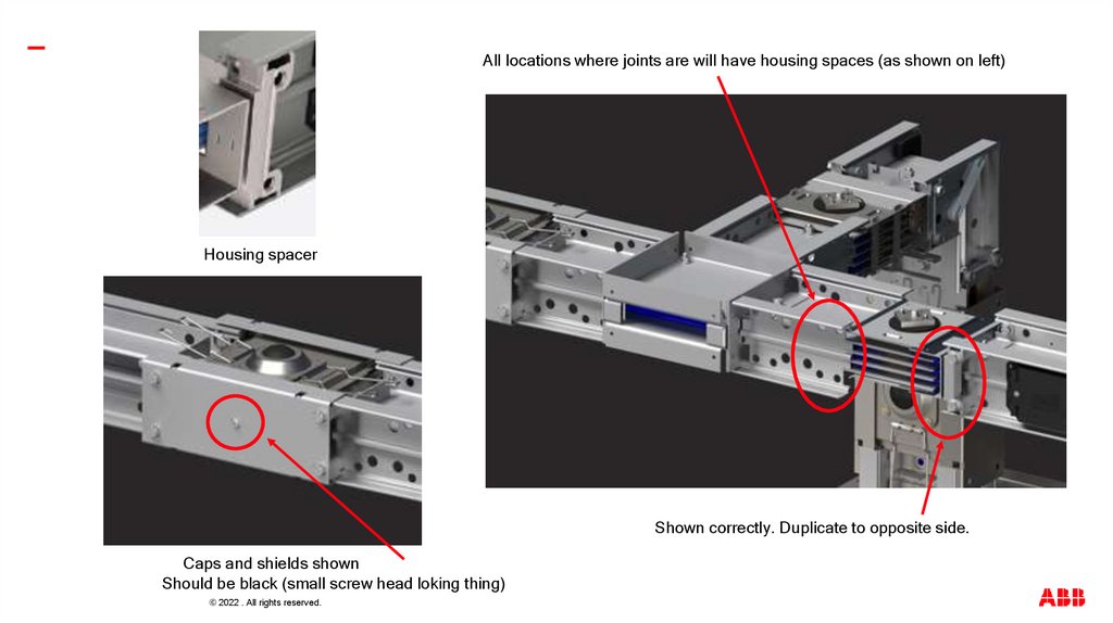
7.
—All locations where joints are will have housing spaces (as shown on left)
Housing spacer
Shown correctly. Duplicate to opposite side.
Caps and shields shown
Should be black (small screw head loking thing)
© 2022 . All rights reserved.
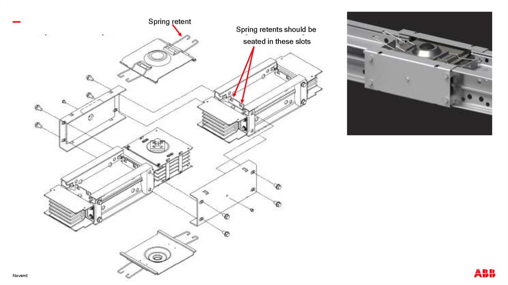
8.
—Spring retent
Spring retents should be
seated in these slots
November 9, 2022
Slide 8
© 2022 . All rights reserved.
9.
—Off white/light green on joint insulators where circled below
Important colors that should be shown in rendering
Blue epoxy (insulation) on bar ends.
This would only be shown during field install animation.
© 2022 . All rights reserved.
10.
Two joint bolt offerings we have-—
Standard offering (double headed break-off bolt)
Optional offering (joint guard bolt with Color indicating head).
We will likely showcase this during one of the animations as a zoom.
© 2022 . All rights reserved.