


 mechanics
Similar presentations:
 Engine")


Mechanical System
1.
GW4D20 ENGINEMECHANICAL SYSTEM
2.
Course Target1.GW4D20 Diesel Engine Parameter & Structure
2.GW4D20 Diesel Engine Assembly Operation
3.GW4D20 Diesel Engine Service Notice
2/62
3.
Topics一、GW4D20 Diesel Engine General Instruction
二、GW4D20 Diesel Engine Basic Parameter
三、GW4D20 Mechanical System
3/62
4.
Ⅰ.GW4D20 Diesel Engine General IntroductionGW4D20 diesel engine with turbocharger system is
developed by Great Wall Motors company itself with great
performance, 4 cylinders in-line, force coolant, ω-shaped
combustion chamber, 16 valves, double top-positioned
camshaft DOHC , inter-cooler, common rail fuel supply
system, VGT system with electronic control EGR valve,
powerful, well economic, high durability, low-temperature
start easy emission standard Euro Ⅳ、 Euro V。
4/62
5.
GW4D20 Engine FigureFront Side
VGT Turbo
Steering
Pump Pulley
Idler
pulley
Tensioner
Pulley Assy
Idler
pulley
Alternator
Compressor
5/62
6.
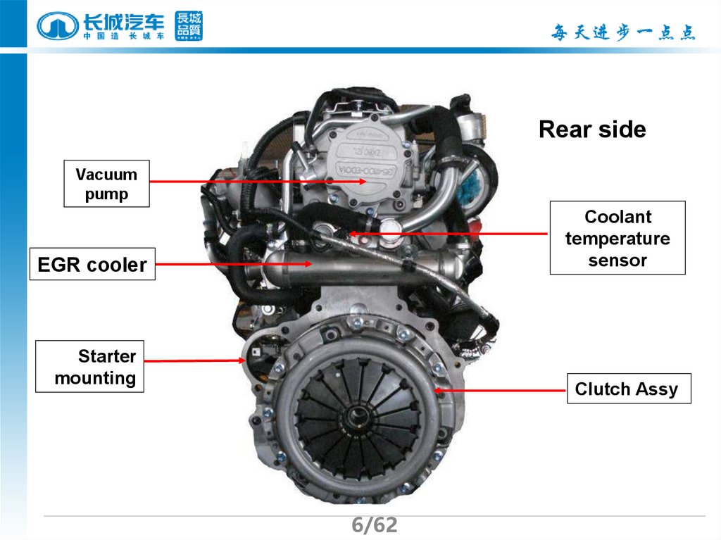
Rear sideVacuum
pump
Coolant
temperature
sensor
EGR cooler
Starter
mounting
Clutch Assy
6/62
7.
Left sideAir inlet
EGR valve
Highpressure
fuel pump
Knock sensor
Upper
cylinder
block
lower
cylinder
block
Water out
pipe
compressor
7/62
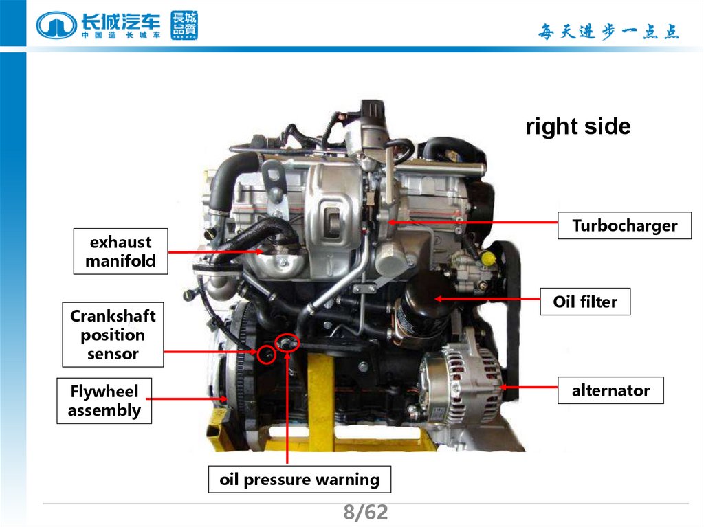
8.
right sideTurbocharger
exhaust
manifold
Oil filter
Crankshaft
position
sensor
alternator
Flywheel
assembly
oil pressure warning
8/62
9.
Top sideVacuum
regulator
Injector
Camshaft
position sensor
High
pressure
fuel rail
9/62
Rail pressure
sensor
10.
II. GW4D20 Diesel Engine ParametersItem
Technical specifications
Type
4 cylinder in-line, water cooling, common rail, 16
valves, DOHC, VGT, electronic controller EGR,
inter cooler
Combustion
chamber type
Necking ω shaped
Bore×stroke
83.1×92 mm
Compression
ratio
16.7∶1
Displacement
1.996 L
Working order
1—3—4—2
Rated power/rpm 110 4000 kw/r/min
Max. torque/rpm
310 1800 2800 N·m/r/min
10/62
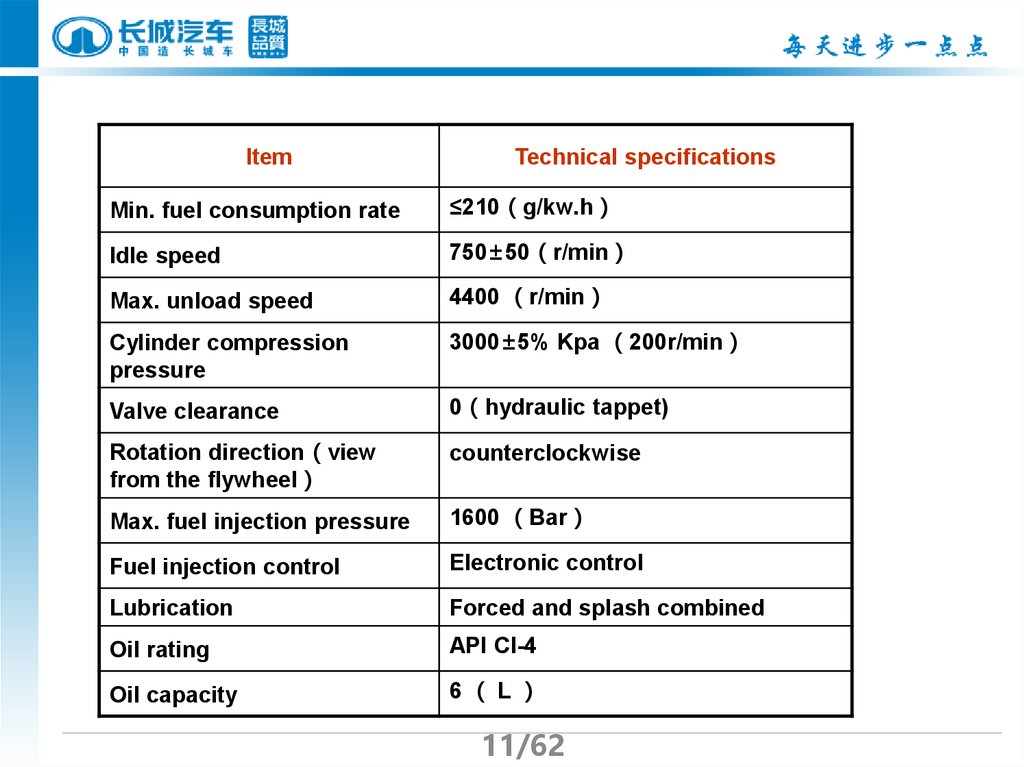
11.
ItemTechnical specifications
Min. fuel consumption rate
≤210 g/kw.h
Idle speed
750±50 r/min
Max. unload speed
4400 r/min
Cylinder compression
pressure
3000±5% Kpa 200r/min
Valve clearance
0 hydraulic tappet)
Rotation direction view
from the flywheel
counterclockwise
Max. fuel injection pressure
1600 Bar
Fuel injection control
Electronic control
Lubrication
Forced and splash combined
Oil rating
API CI-4
Oil capacity
6 L
11/62
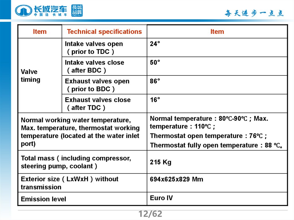
12.
ItemValve
timing
Technical specifications
Item
Intake valves open
prior to TDC
24°
Intake valves close
after BDC
50°
Exhaust valves open
prior to BDC
86°
Exhaust valves close
after TDC
16°
Normal working water temperature,
Max. temperature, thermostat working
temperature (located at the water inlet
port)
Normal temperature 80℃-90℃ Max.
temperature 110℃
Thermostat open temperature 76℃
Thermostat fully open temperature 88 ℃。
Total mass including compressor,
steering pump, coolant
215 Kg
Exterior size LxWxH without
transmission
694x625x829 Mm
Emission level
Euro IV
12/62
13.
GW4D20 other major component technicalspecifications
Technical specifications
Item
Starter
Alternator
turbochar
ger
12V
Volt
2 KW
Output power
14.5±0.3 V
Regulation voltage
rated currency
110A
Specification
VGT
210000 r/min
Max. speed
760 ℃
Max. continuous
working temperature
2800 r/min
Max. speed
Vacuum
pump
Battery
-90 kPa
Max. vacuum
Vacuum approach
time
Rated voltage
To reach up to 50kPa less than 5
s(400 r/min)
13/62
14V
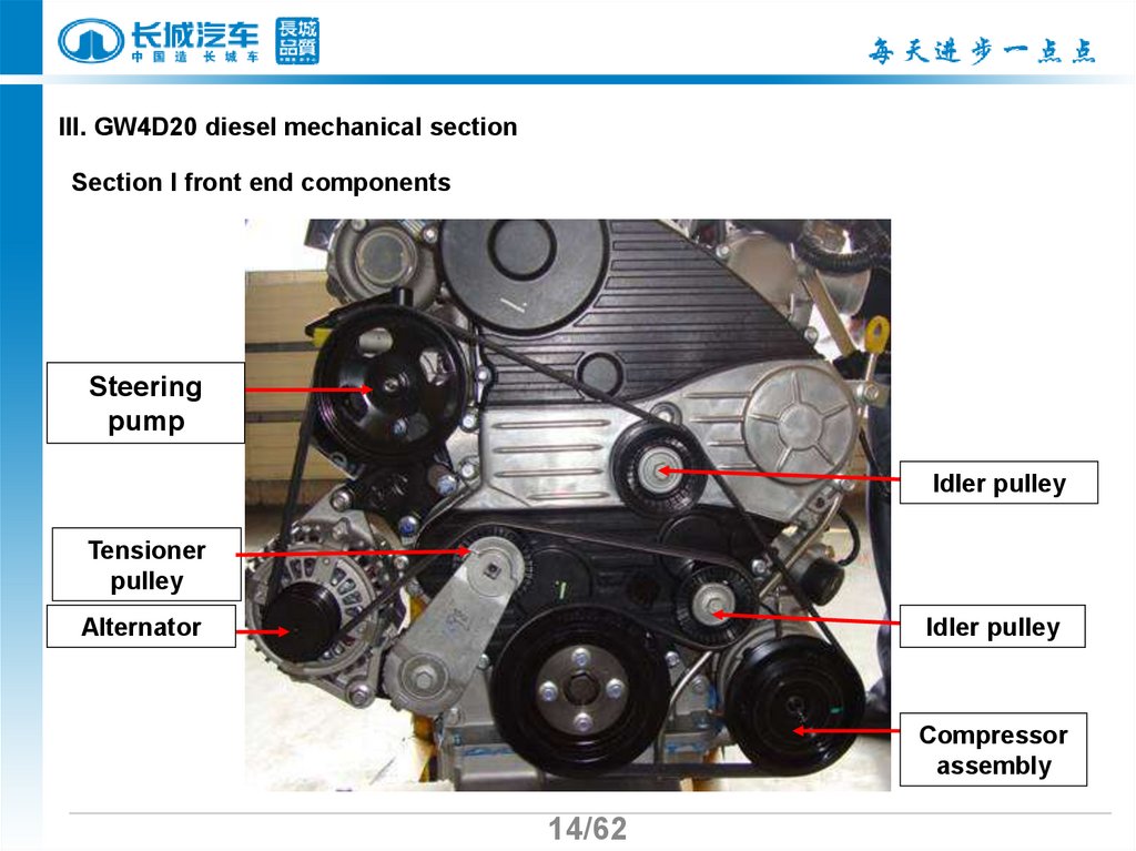
14.
III. GW4D20 diesel mechanical sectionSection I front end components
Steering
pump
Idler pulley
Tensioner
pulley
Alternator
Idler pulley
Compressor
assembly
14/62
15.
II. Notes in removing the alternator beltRemove the belt turn the tensioner clockwise with torque wrench
with on hand, put the tensioner to the bottom position; while
pushing out the belt on the idler pulley with the other hand, then
loose the tensioner and take the whole belt off.
Tensioner
stopper
15/62
16.
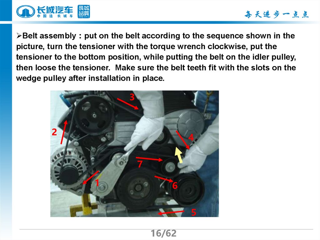
Belt assembly put on the belt according to the sequence shown in thepicture, turn the tensioner with the torque wrench clockwise, put the
tensioner to the bottom position, while putting the belt on the idler pulley,
then loose the tensioner. Make sure the belt teeth fit with the slots on the
wedge pulley after installation in place.
3
2
4
7
1
6
5
16/62
17.
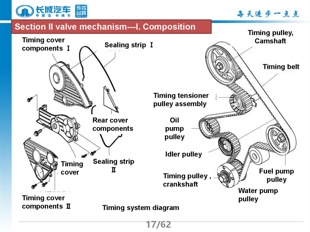
Section II valve mechanism---I. CompositionTiming cover
components Ⅰ
Sealing strip Ⅰ
Timing pulley,
Camshaft
Timing belt
Timing tensioner
pulley assembly
Rear cover
components
Oil
pump
pulley
Idler pulley
Timing
cover
Timing cover
components Ⅱ
Sealing strip
Ⅱ
Timing pulley ,
crankshaft
Timing
system diagram
正时系统示意图
17/62
Fuel pump
pulley
Water pump
pulley
18.
Timing systemTiming pulley
Camshaft
Timing belt
Timing tensioner
pulley
Pulley, Highpressure fuel
pump
Water pump
pulley
Oil pump pulley
Timing pulley
crankshaft
Timing idler pulley
18/62
19.
The features of timing system:There are totally 7 pulleys in the timing system, more pulleys are involved in
the transmission, big span in transmission, big tension in the transmission ;
To make sure that the timing teeth belt has enough tension, and avoid
jumping teeth, teeth fall off and compensation for the extending of timing belt,
the system adopts the automatic tension design. Because the tensioner pulley
is eccentric shaft bearings design, and the tensioner pulley suffers and offers
great tension, then it requires high performance for the component itself and
assembly.
19/62
20.
Timing tensioner pulleyTiming idler pulley
Notice:
Timing belt have
to be changed at
80000km
Timing belt
20/62
21.
II. timing pulley changeImportant notes in changing timing pulley:
environment must be clean
correct timing position
Correct tightening torque
The direction and sequence to put in the belt
Validate the timing
21/62
22.
1.check if the belt is good and take the timing pulley offCheck if scratch and wear and
missing teeth and oil and water are
on the belt
Loose the tightening bolt of the
tensioner, take off the tensioner
22/62
23.
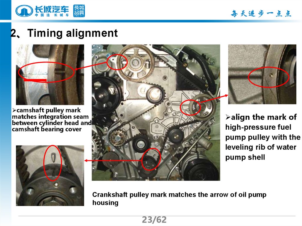
2、Timing alignmentcamshaft pulley mark
matches integration seam
between cylinder head and
camshaft bearing cover
align the mark of
high-pressure fuel
pump pulley with the
leveling rib of water
pump shell
Crankshaft pulley mark matches the arrow of oil pump
housing
23/62
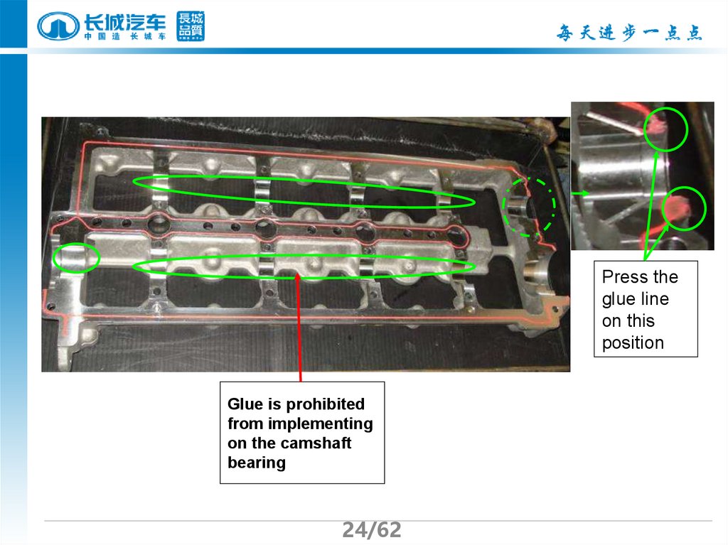
24.
Press theglue line
on this
position
Glue is prohibited
from implementing
on the camshaft
bearing
24/62
25.
3、Installing oftiming belt
Put the belt according to order 1-7 make
sure the belt contact with the pulley firmly
without loosing except the idler pulley.
6
Process
1 timing pulley ,crankshaft
7
2 idler pulley
3 oil pump pulley
5
4 water pump pulley
5 High-pressure fuel pump pulley
3
4
2
6 camshaft pulley
7 Timing tensioner
1
25/62
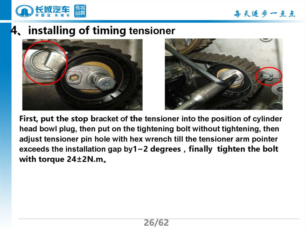
26.
4、installing of timing tensionerFirst, put the stop bracket of the tensioner into the position of cylinder
head bowl plug, then put on the tightening bolt without tightening, then
adjust tensioner pin hole with hex wrench till the tensioner arm pointer
exceeds the installation gap by1~2 degrees finally tighten the bolt
with torque 24±2N.m。
26/62
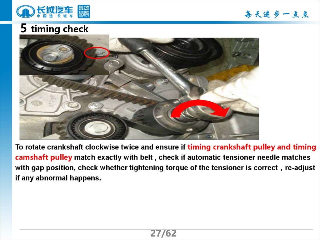
27.
5 timing checkTo rotate crankshaft clockwise twice and ensure if timing crankshaft pulley and timing
camshaft pulley match exactly with belt , check if automatic tensioner needle matches
with gap position, check whether tightening torque of the tensioner is correct re-adjust
if any abnormal happens.
27/62
28.
Chapter IIICylinder head
I cylinder head composition
Cylinder diesel GW4D20 is made of aluminum alloy there are water
jacket and intake & exhausting manifolds and lubrication gallery in the
cylinder , there are seat hole and flat surface for fuel injector &glow plug &
valve seat ring & hydraulic tappet & rocker arm & cylinder head cover.
The exhaust & Intake valves and valve guide and exhaust & Intake
camshaft assemblies and exhaust & Intake manifolds and rocker arm and
hydraulic tappet and fuel injector and glow plugs and high-pressure fuel rail
are assembled on the cylinder head.
28/62
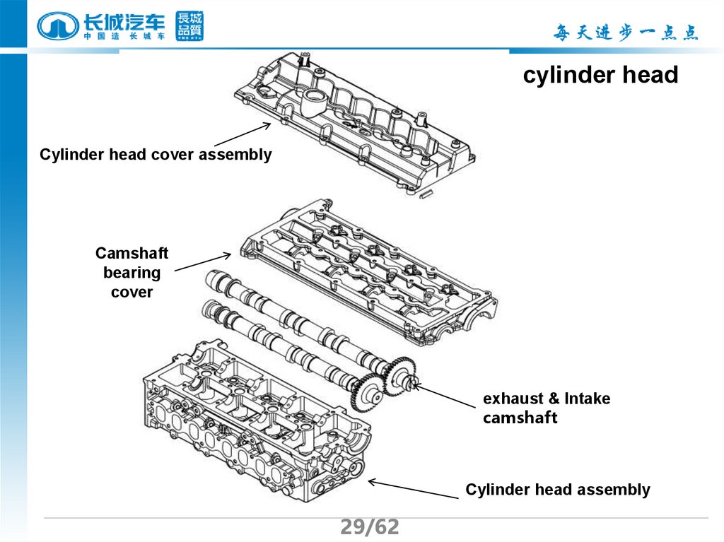
29.
cylinder headCylinder head cover assembly
Camshaft
bearing
cover
exhaust & Intake
camshaft
Cylinder head assembly
29/62
30.
Oil passageOil inlet
30/62
31.
glow plughole
Oil return
hole
Injector hole
31/62
Exhaust valve seat
Cylinder head bolts
Oil inlet
hole
Intake valve seat
water return hole(small cycle)-water inlet hole (big cycle)
32.
II camshaft and Intake & Exhaust valve componentsDouble Overhead Camshaft is used for GW4D20 diesel ,the DOHC
includes Intake & exhaust camshafts, each camshaft has 8 cams ,each cam
controls open/close of one valve.
Exhaust camshaft is the drive shaft , the intake camshaft is driven through the chain,
there is a signal panel installed in front of the intake camshaft, the front oil seal is
located at the exhaust camshaft side, the vacuum pump is at the read end of exhaust
camshaft.
Intake camshaft
exhaust camshaft
signal panel, camshaft
32/62
33.
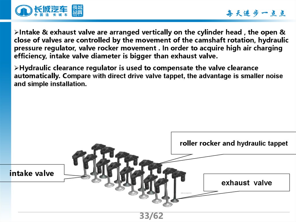
Intake & exhaust valve are arranged vertically on the cylinder head , the open &close of valves are controlled by the movement of the camshaft rotation, hydraulic
pressure regulator, valve rocker movement . In order to acquire high air charging
efficiency, intake valve diameter is bigger than exhaust valve.
Hydraulic clearance regulator is used to compensate the valve clearance
automatically. Compare with direct drive valve tappet, the advantage is smaller noise
and simple installation.
roller rocker and hydraulic tappet
intake valve
exhaust valve
33/62
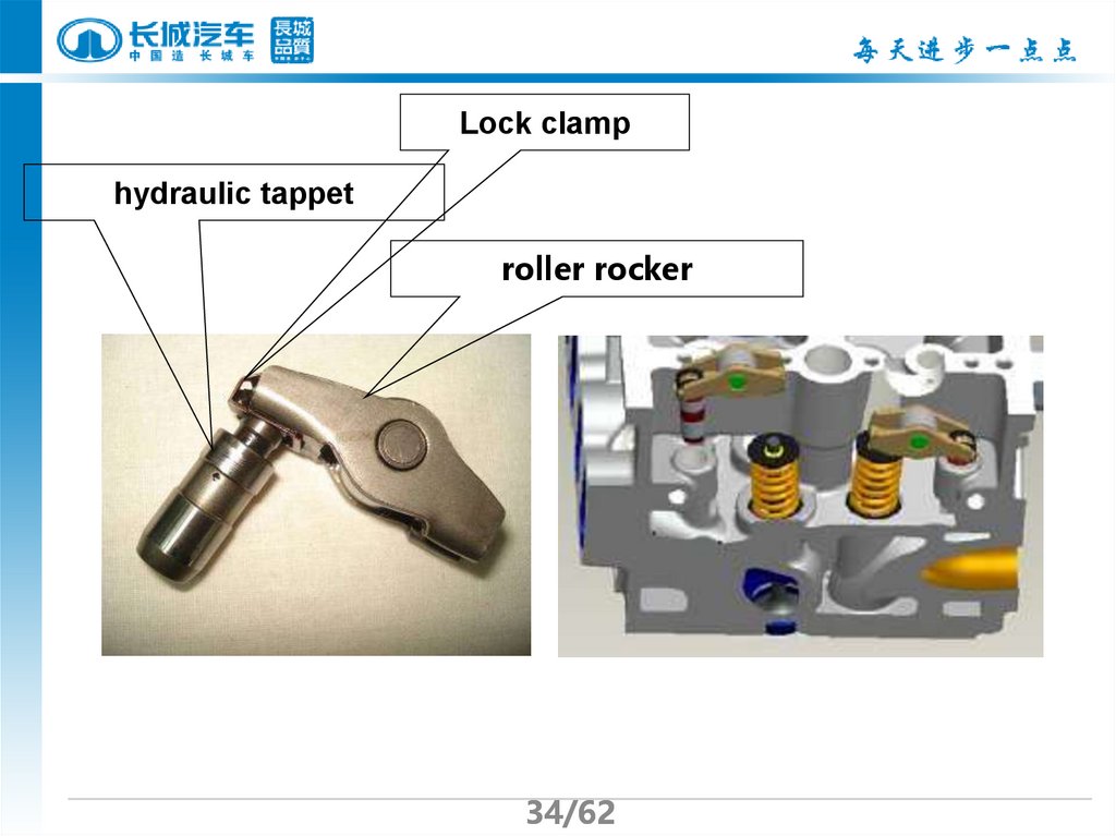
34.
Lock clamphydraulic tappet
roller rocker
34/62
35.
III notices in installation1. The water outlet pipe set at the read end of the cylinder head and
installation position are interference fit , outlet pipe assembly pressed into the
end to apply a round of sealant 962T on the pressing end of the water outlet set,
the sealant width is 3~5mm ,the thickness is 0.5mm. The water outlet pipe
connector must align with the mark on the cylinder head. Apply Loctite 262
sealant to the thread of the coolant temperature sensor to prevent from water
leaking.
coolant temperature
sensor
Mark for
alignment
Pressing end of water outlet pipe
35/62
36.
2. notices in intake & exhaust camshaft installationMark alignment align the” mark on the intake & exhaust camshafts,
while leveling with the upper coupling surface of the cylinder head;
Install the plug cover apply clean lubrication oil on the outer circle of the
rear plug cover of the intake camshaft, then put it into the rear plug cover hole,
then install the camshaft bearing cover. Make sure the plug cover hole is clean,
the plug cover is set in place, or it will cause poor sealant of the plug cover
and oil leakage.
Align the
marks
correctly
Put the plug
cover in place
36/62
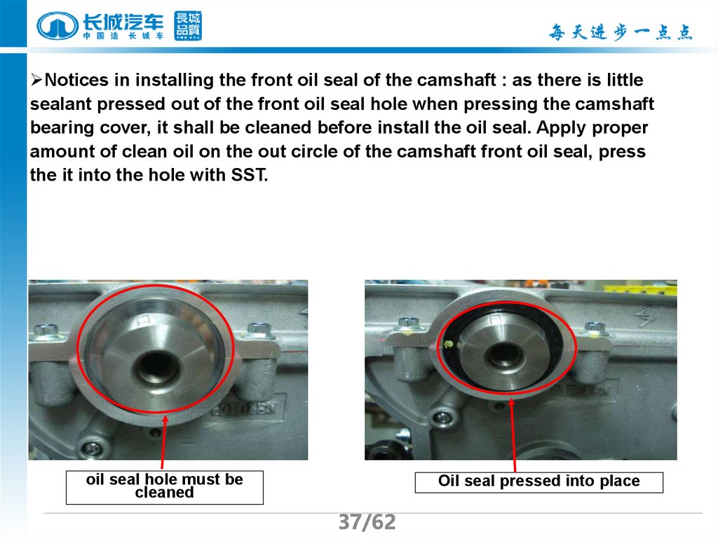
37.
Notices in installing the front oil seal of the camshaft : as there is littlesealant pressed out of the front oil seal hole when pressing the camshaft
bearing cover, it shall be cleaned before install the oil seal. Apply proper
amount of clean oil on the out circle of the camshaft front oil seal, press
the it into the hole with SST.
oil seal hole must be
cleaned
Oil seal pressed into place
37/62
38.
3.notices in applying the glue on the camshaft bearing coverClean the camshaft bearing cover, bearing and cylinder head coupling
surface with the carburetor detergent before apply the glue.
Apply one circile of loctite 510 anaerobic adhesive on the camshaft bearing
cover, the requirements are as follows:
①The glue application range is 0.8~1.2mm(Diameter)--outline border
position
②The glue application range is 0.4~0.6mm(Diameter)—middle position,
make sure apply the glue evenly, and avoid the sealant from pressing into
the engine inside.
③The glue lines within 10mm on the 5th intake camshaft hole shall be
pressed evenly, never smear it inside the hole.
④glue and impurity is not allowed to exist on the camshaft bearing and
round its edges, ensure the cleanness, or it may lead to camshaft stuck.
38/62
39.
4. Cylinder head tightening10
6
2
3
7
Rear-end
9
5
1
4
8
Use the Angle tightening method, screw up by three steps: the first is screw the
bolt to 50±N.m; the second is to turn spanner by 90°; the third is to turn the
spanner by another 120°
39/62
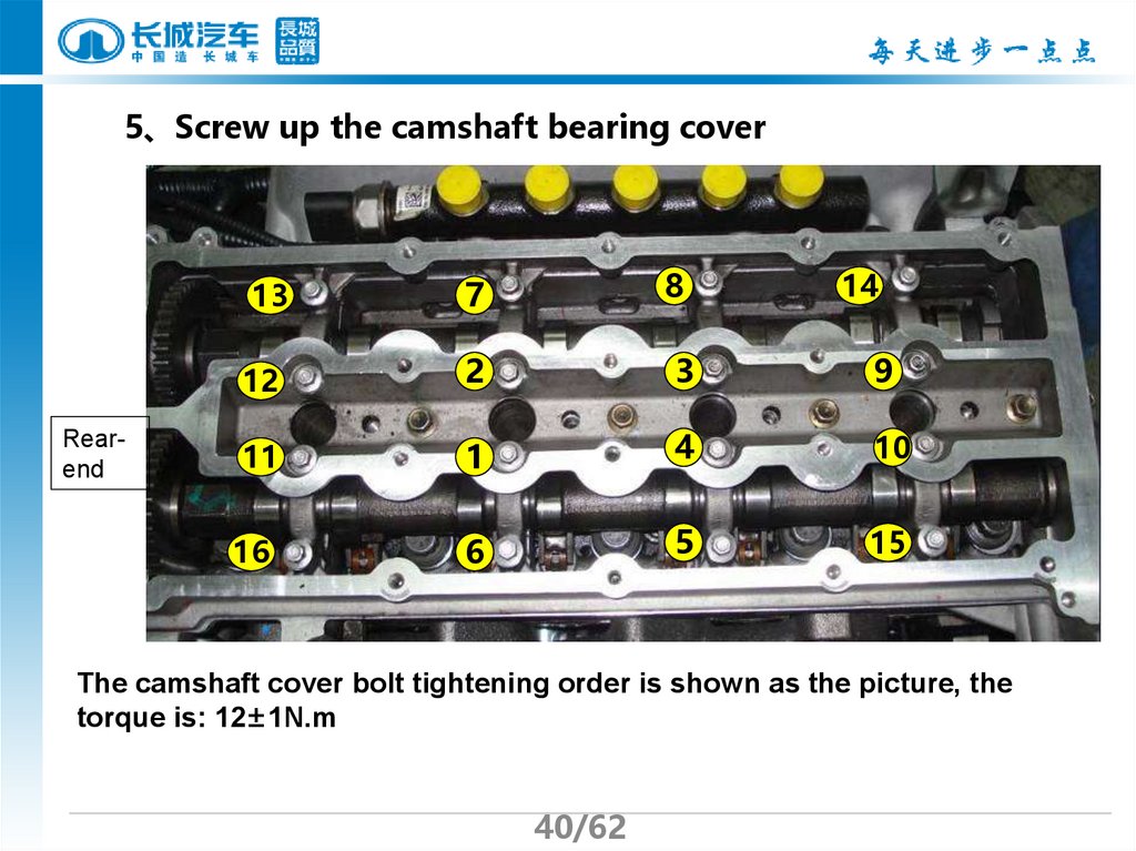
40.
5、Screw up the camshaft bearing cover7
8
12
2
3
9
11
1
4
10
6
5
15
13
Rearend
16
14
The camshaft cover bolt tightening order is shown as the picture, the
torque is: 12±1N.m
40/62
41.
Chapter IV the cylinder blockCylinder block feature
The cylinder of GW4D20 adopts
the equally split type structure, falls
into the upper and lower cylinder
block, the lower cylinder and the
main bearing cover is formed into
one part. In terms of the flat bottom
type cylinder block and short skirt
cylinder block, this structural design
strengthens the structural strength
a lot, then engine has enough
rigidity when generating explosive
pressure and outputting big torque.
41/62
The
upper
cylinder
block
The
lower
cylinder
block
42.
Piston coolingoil passage
Engine code is
here
Noliner
Non-liner structure design,
compact structure, small
cylinder bore deformation,
four cooling injectors are
installed on upper cylinder
block to cooling the pistons
to prevent overheating .
Starter location
The starter location is directly designed
on the cylinder block, at the left side of the
engine, the engine code is engraved on
left side, on the upper of engine left
support, engine code ruling is as follows:
42/62
GW4D20
Type code
☆ 201 10 0000 ☆
Star Year
0 Mth S/N
1 Star
No.
No. s No.
No.
43.
Rotor oil pump, oil pump andthe cylinder integrated into one
part, so the engine structure is
more compact.
Oil cooler
seat
Oil pump chamber
The oil filter is installed on the
right of the engine, oil filter and
the cooler adopts one integrity.
Align the locating gap on the
cooler with the convex mark on
the cooler seat properly.
Oil sensor
installation
location
Speed
sensor
installation
location
43/62
44.
II The cylinder bore and piston’s match methodCylinder block
size (Φ/mm)
Mark
Piston grouping
(Φ/mm)
Mark
Match
cylinder
clearance
(mm)
-0.081
-0.090
-0.071
-0.080
1
0.071 0.09
2
0.071 0.09
3
0.071 0.09
83.09 83.10
1
83.1
83.10 83.11
2
83.1
83.11 83.12
3
83.1 -0.061
-0.070
Piston
grouping
When assembling, piston and cylinder
grouping tags must be matched.
Cylinder
block
size
44/62
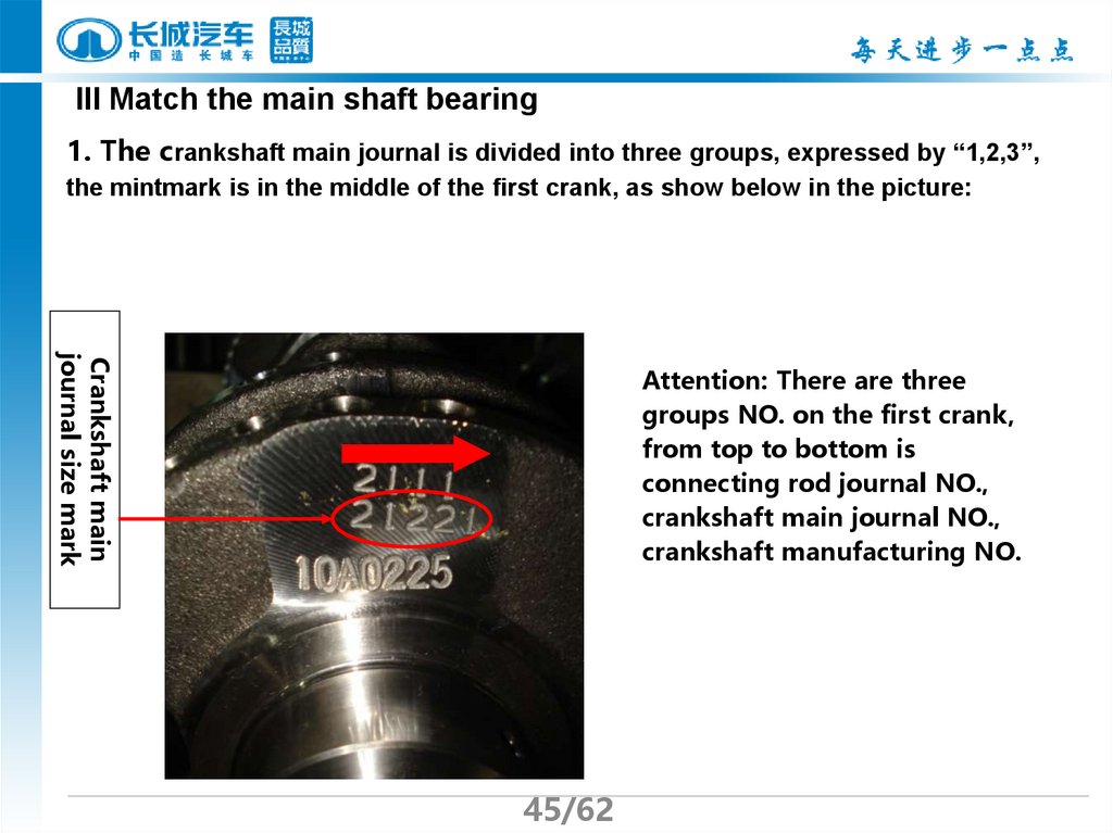
45.
III Match the main shaft bearing1. The crankshaft main journal is divided into three groups, expressed by “1,2,3”,
the mintmark is in the middle of the first crank, as show below in the picture:
Crankshaft main
journal size mark
Attention: There are three
groups NO. on the first crank,
from top to bottom is
connecting rod journal NO.,
crankshaft main journal NO.,
crankshaft manufacturing NO.
45/62
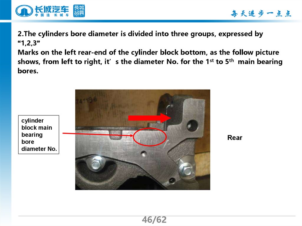
46.
2.The cylinders bore diameter is divided into three groups, expressed by“1,2,3”
Marks on the left rear-end of the cylinder block bottom, as the follow picture
shows, from left to right, it’s the diameter No. for the 1st to 5th main bearing
bores.
cylinder
block main
bearing
bore
diameter No.
Rear
46/62
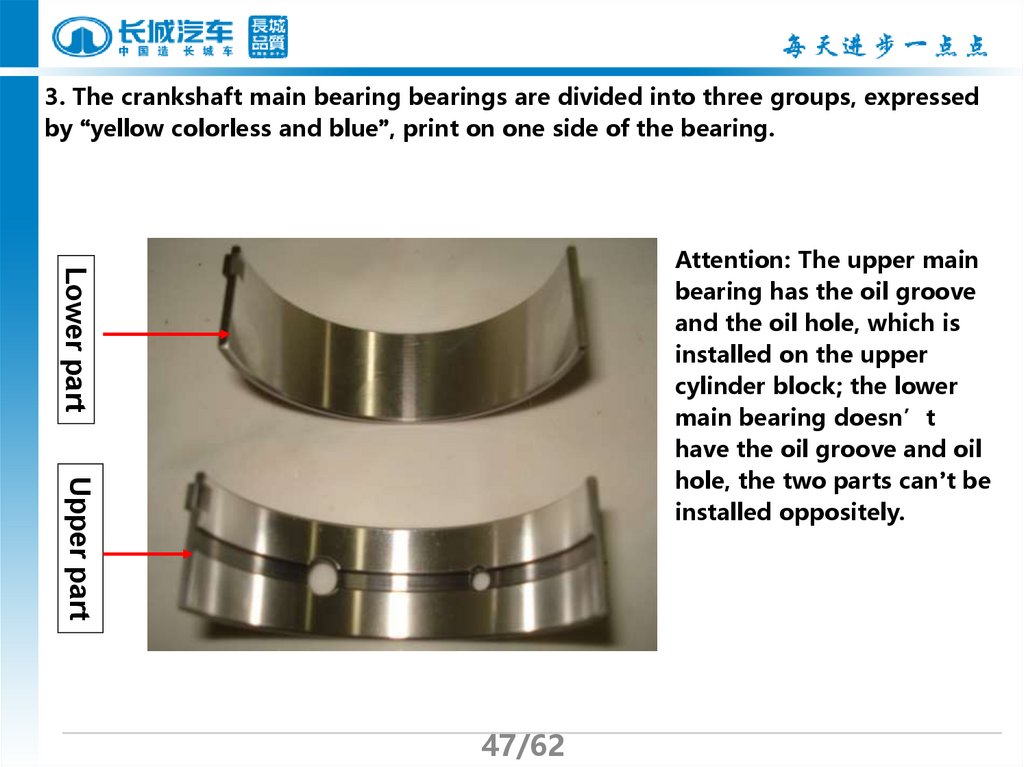
47.
3. The crankshaft main bearing bearings are divided into three groups, expressedby “yellow colorless and blue”, print on one side of the bearing.
Lower part
Attention: The upper main
bearing has the oil groove
and the oil hole, which is
installed on the upper
cylinder block; the lower
main bearing doesn’t
have the oil groove and oil
hole, the two parts can’t be
installed oppositely.
Upper part
47/62
48.
4、The match formula of main bearingCrankshaft main journal size No.+ cylinder
block main journal bore diameter No.
Main bearing
color mark
(mm)
Fit clearance
=2 3
yellow
0.020 0.046
=4
colorless
0.024 0.044
=5 6
blue
0.022 0.048
Select the main bearing according to the match formula. For example:
the first crankshaft main journal size No. is “2”, the first cylinder
block bore diameter No. is “1”, 2+1=3, so choose the “yellow” main
bearing.
48/62
49.
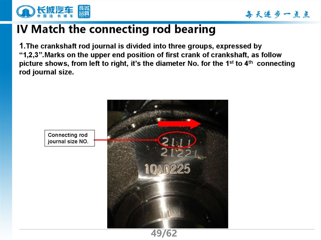
IV Match the connecting rod bearing1.The crankshaft rod journal is divided into three groups, expressed by
“1,2,3”.Marks on the upper end position of first crank of crankshaft, as follow
picture shows, from left to right, it’s the diameter No. for the 1st to 4th connecting
rod journal size.
Connecting rod
journal size NO.
49/62
50.
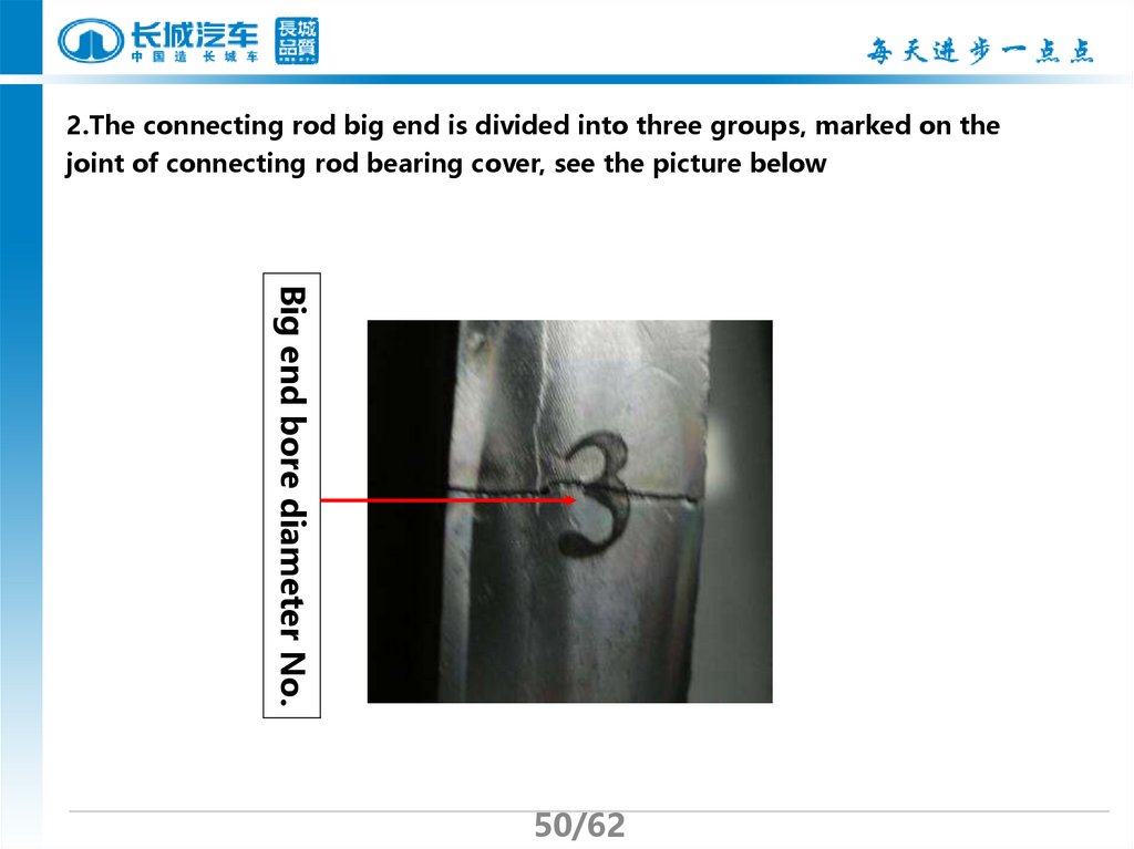
2.The connecting rod big end is divided into three groups, marked on thejoint of connecting rod bearing cover, see the picture below
Big end bore diameter No.
50/62
51.
3. The connecting rod bearings are divided into three groups, expressed by“yellow, colorless and blue”, print on one side of the bearing.
Lower part
Attention: the upper rod
bearing is not smooth
surface, the lower rod
bearing is smooth
surface, there is not oil
hole with both of the
bearings. They can’t
install oppositely when
assembling.
Upper part
51/62
52.
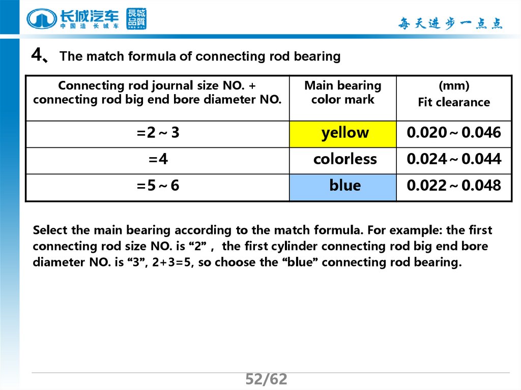
4、The match formula of connecting rod bearingConnecting rod journal size NO. +
connecting rod big end bore diameter NO.
Main bearing
color mark
(mm)
Fit clearance
=2 3
yellow
0.020 0.046
=4
colorless
0.024 0.044
=5 6
blue
0.022 0.048
Select the main bearing according to the match formula. For example: the first
connecting rod size NO. is “2” the first cylinder connecting rod big end bore
diameter NO. is “3”, 2+3=5, so choose the “blue” connecting rod bearing.
52/62
53.
V. Notices in installation1、The notices in installing the piston and connecting rod.
According to the cylinder bore’s grouping mark to choose the corresponding
piston.
The piston and connecting rod shall be assembled according to the forward mark,
this means: the top mark of piston, the bulge of connecting rod body and the
bulge of connecting rod big end cover side plane should be in the same side, face
the front of the engine.
53/62
54.
When assembling the piston ring, the first gas ring is silvery white, thesecond gas ring is dark grey, the two rings can’t be exchanged, the upward
mark “A TOP” on the ring should face the top of the piston, for avoiding
cylinder getting stuck, the opening direction of the rings can’t be on the
thrust side direction, and the adjacent rings opening shall be staggered by
180 degrees, shows as the picture 2:
The opening
of first gas
ring
1
2
3
Oil ring
opening
The opening
of second gas
ring
Forward mark
54/62
The upward mark “A
TOP”
55.
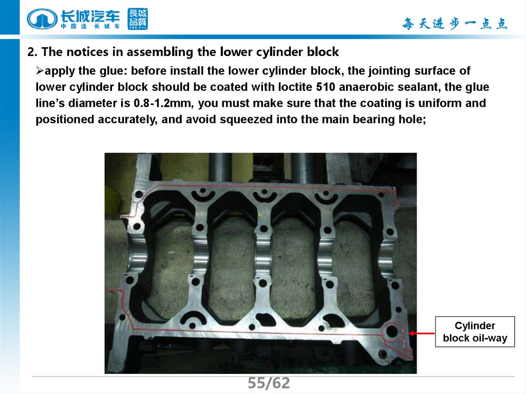
2. The notices in assembling the lower cylinder blockapply the glue: before install the lower cylinder block, the jointing surface of
lower cylinder block should be coated with loctite 510 anaerobic sealant, the glue
line’s diameter is 0.8-1.2mm, you must make sure that the coating is uniform and
positioned accurately, and avoid squeezed into the main bearing hole;
Cylinder
block oil-way
55/62
56.
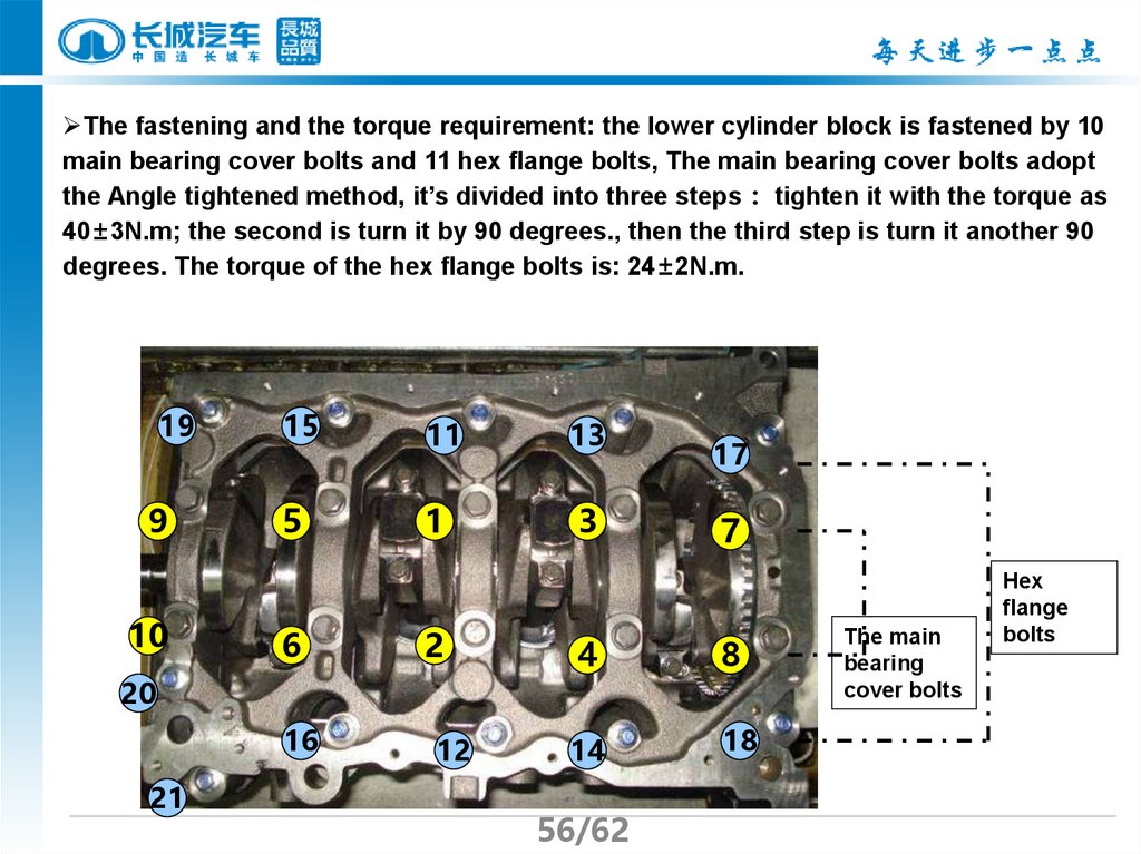
The fastening and the torque requirement: the lower cylinder block is fastened by 10main bearing cover bolts and 11 hex flange bolts, The main bearing cover bolts adopt
the Angle tightened method, it’s divided into three steps tighten it with the torque as
40±3N.m; the second is turn it by 90 degrees., then the third step is turn it another 90
degrees. The torque of the hex flange bolts is: 24±2N.m.
19
9
10
15
5
6
11
1
2
20
16
21
12
13
…
3
17
7
4
8
14
18
56/62
The main
bearing
cover bolts
Hex
flange
bolts
57.
3. The notices in assembling the oil pumpClean: clean the joint surface of oil
pump, the front oil seal hole of
crankshaft, the joint surface of
cylinder block and oil pump
Make sure that the front oil seal of
crankshaft and oil pump seal ring
assembly are set in place without and
deflection, damage and jumping from
the slot.
Coating the glue: coating the 587
sealant as the picture, the diameter is
2-3mm
Put exterior rotor into the pump
chamber on the upper cylinder block,
the side with mark of the rotor faces
the inside of the pump chamber
bottom on the cylinder block.
57/62
Glue-coating
track
Exterior rotor
mark
58.
Course review1.The overview of GW4D20 diesel engine
2.The Basic parameters of GW4D20 diesel engine
3.The mechanical part of GW4D20 diesel engine
58/62