Similar presentations:


Measurement Overview
1.
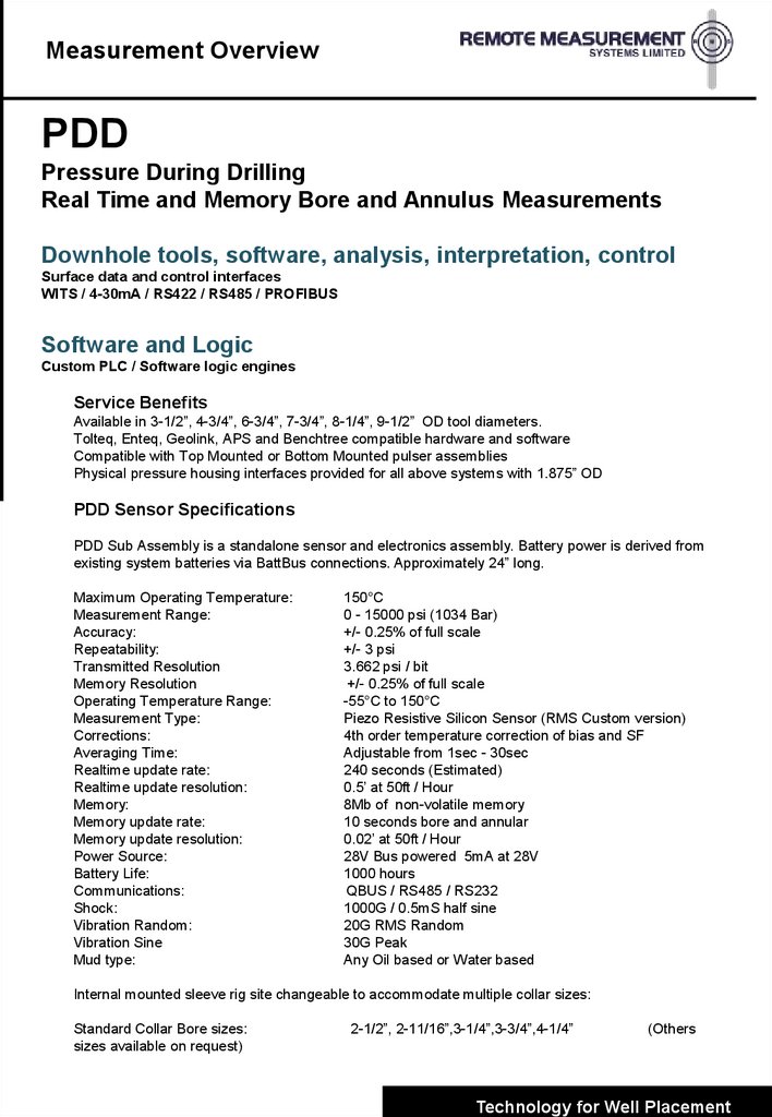
Measurement OverviewPDD
Pressure During Drilling
Real Time and Memory Bore and Annulus Measurements
Downhole tools, software, analysis, interpretation, control
Surface data and control interfaces
WITS / 4-30mA / RS422 / RS485 / PROFIBUS
Software and Logic
Custom PLC / Software logic engines
Service Benefits
Available in 3-1/2”, 4-3/4”, 6-3/4”, 7-3/4”, 8-1/4”, 9-1/2” OD tool diameters.
Tolteq, Enteq, Geolink, APS and Benchtree compatible hardware and software
Compatible with Top Mounted or Bottom Mounted pulser assemblies
Physical pressure housing interfaces provided for all above systems with 1.875” OD
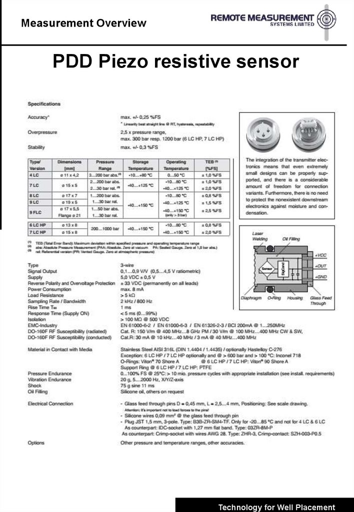
PDD Sensor Specifications
PDD Sub Assembly is a standalone sensor and electronics assembly. Battery power is derived from
existing system batteries via BattBus connections. Approximately 24” long.
Maximum Operating Temperature:
Measurement Range:
Accuracy:
Repeatability:
Transmitted Resolution
Memory Resolution
Operating Temperature Range:
Measurement Type:
Corrections:
Averaging Time:
Realtime update rate:
Realtime update resolution:
Memory:
Memory update rate:
Memory update resolution:
Power Source:
Battery Life:
Communications:
Shock:
Vibration Random:
Vibration Sine
Mud type:
150°C
0 - 15000 psi (1034 Bar)
+/- 0.25% of full scale
+/- 3 psi
3.662 psi / bit
+/- 0.25% of full scale
-55°C to 150°C
Piezo Resistive Silicon Sensor (RMS Custom version)
4th order temperature correction of bias and SF
Adjustable from 1sec - 30sec
240 seconds (Estimated)
0.5’ at 50ft / Hour
8Mb of non-volatile memory
10 seconds bore and annular
0.02’ at 50ft / Hour
28V Bus powered 5mA at 28V
1000 hours
QBUS / RS485 / RS232
1000G / 0.5mS half sine
20G RMS Random
30G Peak
Any Oil based or Water based
Internal mounted sleeve rig site changeable to accommodate multiple collar sizes:
Standard Collar Bore sizes:
sizes available on request)
2-1/2”, 2-11/16”,3-1/4”,3-3/4”,4-1/4”
(Others
Technology for Well Placement
2.
Measurement OverviewPDD Processing
•Raw pressure transmitted (Annular and Bore as GENERIC
Variables – Units PSI
•Variables Tagged an passed via WITS to RMS offline PC which
calculates ECD / and other drilling parameters
• RMS offline computer sends all WITS and corrected data to
Digidrill PC for plotting and LAS file generation
• Digidrill PC plots and stores data as function of depth and time.
• PDD memory data processed through Digidrill correlator for depth
time correlation and LAS file generation.
Technology for Well Placement
3.
Measurement OverviewPDD Applications
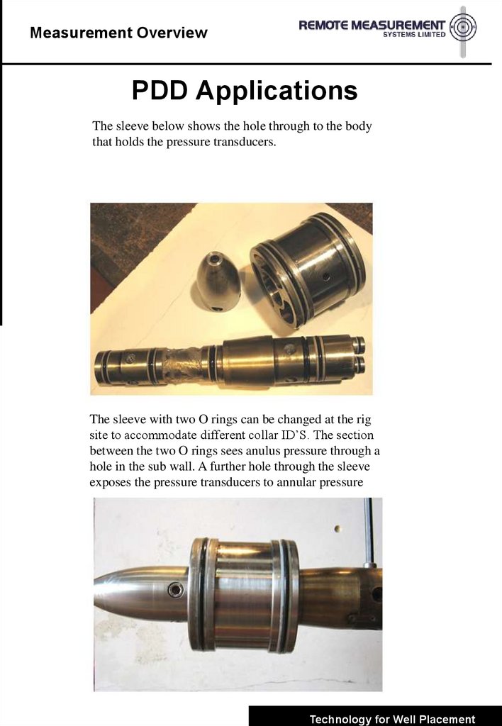
The sleeve below shows the hole through to the body
that holds the pressure transducers.
The sleeve with two O rings can be changed at the rig
site to accommodate different collar ID’S. The section
between the two O rings sees anulus pressure through a
hole in the sub wall. A further hole through the sleeve
exposes the pressure transducers to annular pressure
Technology for Well Placement
4.
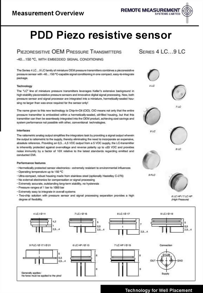
Measurement OverviewPDD Piezo resistive sensor
Technology for Well Placement
5.
Measurement OverviewPDD Piezo resistive sensor
Technology for Well Placement
6.
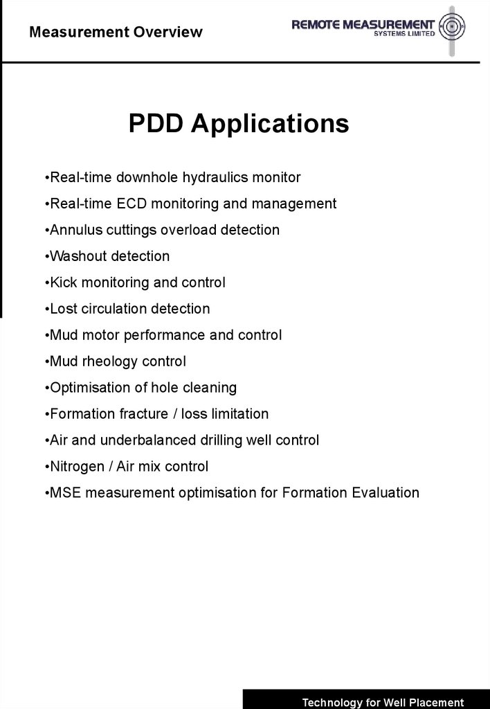
Measurement OverviewPDD Applications
•Real-time downhole hydraulics monitor
•Real-time ECD monitoring and management
•Annulus cuttings overload detection
•Washout detection
•Kick monitoring and control
•Lost circulation detection
•Mud motor performance and control
•Mud rheology control
•Optimisation of hole cleaning
•Formation fracture / loss limitation
•Air and underbalanced drilling well control
•Nitrogen / Air mix control
•MSE measurement optimisation for Formation Evaluation
Technology for Well Placement
7.
Measurement OverviewManaged Pressure Drilling
•Managing the annular hydraulic pressure profile within the allowed
pressure window
•Well control within this window
•Assistance from modelling tools and automated control systems
MPD may be accomplished by many means including
- Backpressure
- Variable fluid density
- Fluid rheology
- Circulation friction
- Hole geometry
- Using an active device to manipulate the mud gradient and dynamic pressure
Aims of MPD
•Control Abnormal Pressures
- Borehole Quality (Sloughing or Collapse)
- Blow out prevention
• Stay within Fracture Gradient
- Ensure Casing Shoe Integrity
- Limit or Stop Lost Circulation
• Restrict or Eliminate Reservoir Damage
- Prevent Mud / Mud Solids Entering Reservoir Porosity
- Maximise Production Potential
Technology for Well Placement
8.
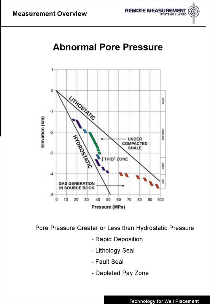
Measurement OverviewAbnormal Pore Pressure
Pore Pressure Greater or Less than Hydrostatic Pressure
- Rapid Deposition
- Lithology Seal
- Fault Seal
- Depleted Pay Zone
Technology for Well Placement
9.
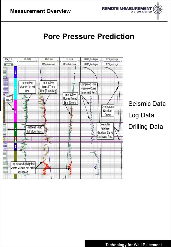
Measurement OverviewPore Pressure Prediction
Seismic Data
Log Data
Drilling Data
Technology for Well Placement
10.
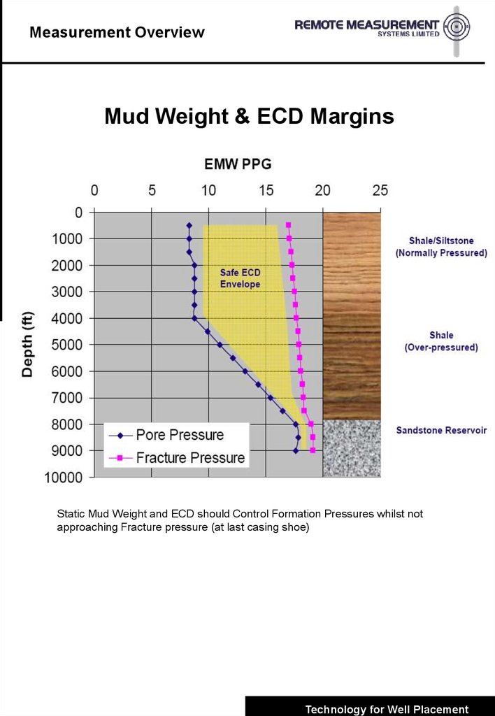
Measurement OverviewMud Weight & ECD Margins
Static Mud Weight and ECD should Control Formation Pressures whilst not
approaching Fracture pressure (at last casing shoe)
Technology for Well Placement
11.
Measurement OverviewFailure to Control Pressure
•Shale Caving
•Borehole Rugosity
•Tight Spots
•Well Collapse
•Well Kicks
•Blow Out
•Lost Circulation
•Reservoir Damage
Technology for Well Placement
12.
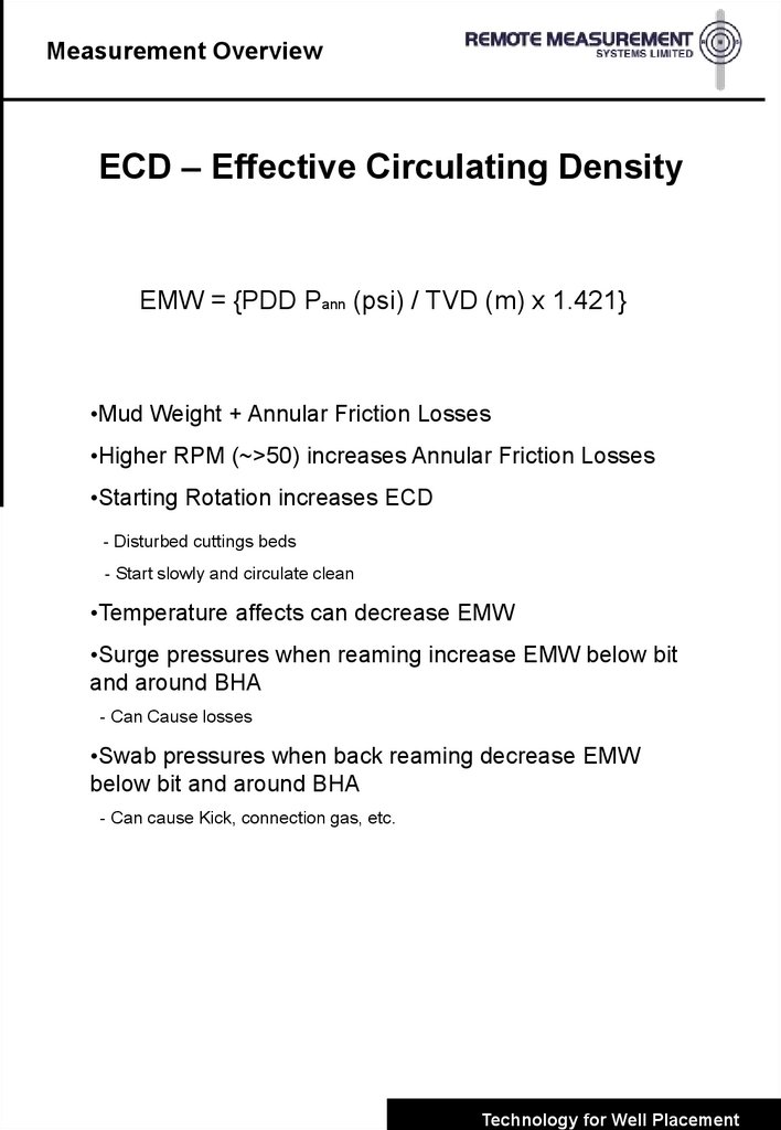
Measurement OverviewECD – Effective Circulating Density
EMW = {PDD Pann (psi) / TVD (m) x 1.421}
•Mud Weight + Annular Friction Losses
•Higher RPM (~>50) increases Annular Friction Losses
•Starting Rotation increases ECD
- Disturbed cuttings beds
- Start slowly and circulate clean
•Temperature affects can decrease EMW
•Surge pressures when reaming increase EMW below bit
and around BHA
- Can Cause losses
•Swab pressures when back reaming decrease EMW
below bit and around BHA
- Can cause Kick, connection gas, etc.
Technology for Well Placement
13.
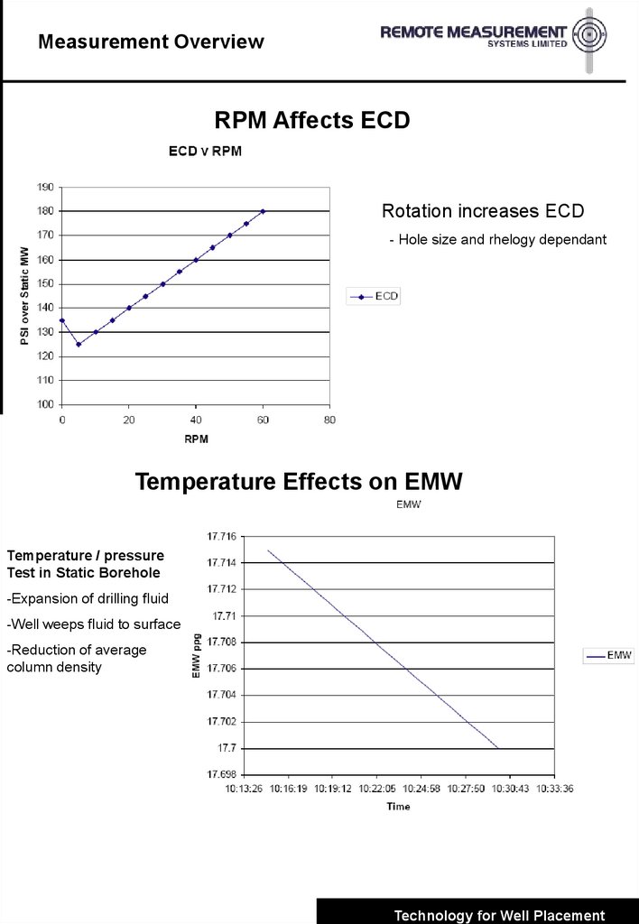
Measurement OverviewRPM Affects ECD
Rotation increases ECD
- Hole size and rhelogy dependant
Temperature Effects on EMW
Temperature / pressure
Test in Static Borehole
-Expansion of drilling fluid
-Well weeps fluid to surface
-Reduction of average
column density
Technology for Well Placement