


 mechanics
Similar presentations:


System Specifications. LWD 1
1. LWD 1
System SpecificationsMarch 7, 2001
© 2001, Halliburton Energy Services, Inc.
1
2. System Specifications
What changes during the drillingof a well that may affect the
selection of an MWD system?
March 7, 2001
© 2001, Halliburton Energy Services, Inc.
2
3. System Specifications
• Hole Size (Collar Size)• Mud Flow Rate
• Mud Density
• Formation Temperature
• Bottom Hole Pressure
March 7, 2001
© 2001, Halliburton Energy Services, Inc.
3
4. System Specifications
Hole SizeUsually decreases with hole depth
Why?
March 7, 2001
© 2001, Halliburton Energy Services, Inc.
4
5. System Specifications
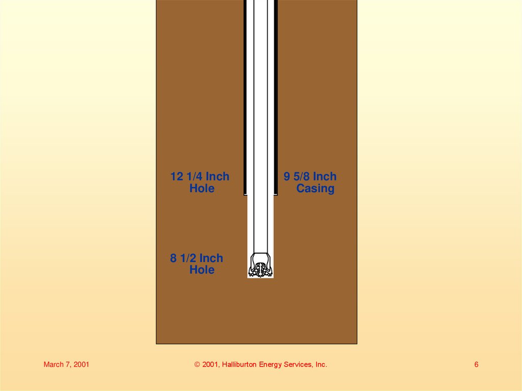
Hole SizeUsually decreases with hole depth
Why?
• Casing or liner is run to isolate shallower
hole sections.
• A smaller diameter drill bit is then required
to pass through the casing.
• Smaller diameter drill collars are used.
March 7, 2001
© 2001, Halliburton Energy Services, Inc.
5
6.
12 1/4 InchHole
9 5/8 Inch
Casing
8 1/2 Inch
Hole
March 7, 2001
© 2001, Halliburton Energy Services, Inc.
6
7. System Specifications
TypicalSystem Collar OD Hole Sizes
3
1200
7- /4 to 11 24 to 12 ¼
1
1
650
6- /2 to 9- /2 8 ½ to 12 ¼
3
Slimhole 4- /4
6 to 6 ½
1
1
Superslim 3- /8 to 3- /2 4 to 5 ?
March 7, 2001
© 2001, Halliburton Energy Services, Inc.
7
8. Hole Size
12 1/4 inch hole8 inch collars
Select
650 or 1200
System
March 7, 2001
8 1/2 inch hole
6-3/4 inch collars
Select
650 system
© 2001, Halliburton Energy Services, Inc.
8
9. System Specifications
Mud Flow RateUsually decreases with hole depth
Why?
March 7, 2001
© 2001, Halliburton Energy Services, Inc.
9
10. System Specifications
Mud Flow RateUsually decreases with hole depth
Why?
• As hole diameter decreases less flow is
required to clean the hole.
• As hole depth increases circulating
pressure also increases
• Flow is reduced to keep the circulating
pressure within limits.
March 7, 2001
© 2001, Halliburton Energy Services, Inc.
10
11. System Specifications
System1500 option
1200
650
Slimhole
March 7, 2001
Flow Range
gpm
1200 to 1500
400 to 1200
1512-4536 l/m
225 to 650
850-2457 l/m
150 to 350
567-1323
Superslim
Straight
60 to 175
Undercut 100 to 220
© 2001, Halliburton Energy Services, Inc.
11
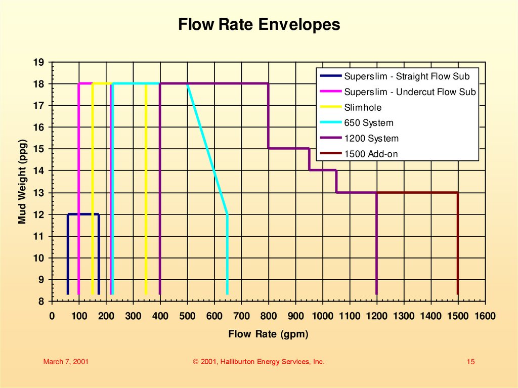
12. Flow Rate
12 1/4 inch hole8 inch collars
850 gpm
Select
1200 System
March 7, 2001
8 1/2 inch hole
6-3/4 inch collars
620 gpm
Select
650 system
© 2001, Halliburton Energy Services, Inc.
12
13. System Specifications
Mud DensityChanges with hole conditions
Why?
March 7, 2001
© 2001, Halliburton Energy Services, Inc.
13
14. System Specifications
Mud DensityChanges with hole conditions
Why?
• Mud density is adjusted to balance the
formation pressure.
• It usually increases with depth, but may
decrease again after casing is set.
March 7, 2001
© 2001, Halliburton Energy Services, Inc.
14
15.
Flow Rate Envelopes19
Superslim - Straight Flow Sub
Mud Weight (ppg)
18
Superslim - Undercut Flow Sub
17
Slimhole
16
650 System
1200 System
15
1500 Add-on
14
13
12
11
10
9
8
0
100
200
300
400
500
600
700
800
900 1000 1100 1200 1300 1400 1500 1600
Flow Rate (gpm)
March 7, 2001
© 2001, Halliburton Energy Services, Inc.
15
16. Mud Density
12 1/4 inch hole8 inch collars
850 gpm
12 ppg
Select
1200 System
March 7, 2001
8 1/2 inch hole
6-3/4 inch collars
620 gpm
13 ppg
Select
650 system
© 2001, Halliburton Energy Services, Inc.
16
17. System Specifications
TemperatureIncreases with true vertical depth
Why?
March 7, 2001
© 2001, Halliburton Energy Services, Inc.
17
18. System Specifications
TemperatureIncreases with true vertical depth
Why?
• Due to conductance of heat from earth’s
core to surface.
• Temperature increases between 0.5°-5°C per
100 m, average 2.5°C per 100 m
• Temperature increases between 0.25°-2.5°F
per 100 ft, average 1.5°F per 100 ft
March 7, 2001
© 2001, Halliburton Energy Services, Inc.
18
19. System Specifications
Temperature– Affects the selection of:
• Pulser
March 7, 2001
© 2001, Halliburton Energy Services, Inc.
19
20. System Specifications
• Pulser Temperature RatingsPulser
Mk VI
Mk VII
Mk VIII
March 7, 2001
Maximum
Temperature
175° C (347° F)
200° C (392° F)
200° C (392° F)
© 2001, Halliburton Energy Services, Inc.
20
21. Temperature
12 1/4 inch hole8 inch collars
850 gpm
12 ppg
100° C at 10,000 ft
Select
1200 System
Any pulser
March 7, 2001
8 1/2 inch hole
6-3/4 inch collars
620 gpm
13 ppg
145° C at 14,000 ft
Select
650 system
Any pulser
© 2001, Halliburton Energy Services, Inc.
21
22. System Specifications
Temperature– Affects the selection of:
• Pulser
• Directional sensor
March 7, 2001
© 2001, Halliburton Energy Services, Inc.
22
23. System Specifications
• Directional Sensor TemperatureRatings
Maximium
Temperature
Sensor
DEP, DEP II
140° C (284° F)
PCD, PCD-K, PCD-R 150° C (302° F)
DM
175° C (347° F)
March 7, 2001
© 2001, Halliburton Energy Services, Inc.
23
24. Temperature
12 1/4 inch hole8 inch collars
850 gpm
12 ppg
100° C at 10,000 ft
Select
6-3/4 inch collars
620 gpm
13 ppg
145° C at 14,000 ft
Select
1200 System
Any pulser
Any directional probe
March 7, 2001
8 1/2 inch hole
650 System
Any pulser
Do not use DEP/DEPII
© 2001, Halliburton Energy Services, Inc.
24
25. System Specifications
Temperature– Affects the selection of:
• Pulser
• Directional sensor
• Gamma sensor
March 7, 2001
© 2001, Halliburton Energy Services, Inc.
25
26. System Specifications
• Gamma Sensor TemperatureRatings
Sensor
PCG, PCG-R
GM
March 7, 2001
Maximum
Temperature
150° C (302° F)
175° C (347° F)
© 2001, Halliburton Energy Services, Inc.
26
27. Temperature
12 1/4 inch hole8 inch collars
850 gpm
12 ppg
100° C at 10,000 ft
Select
6-3/4 inch collars
620 gpm
13 ppg
145° C at 14,000 ft
Select
1200 System
Any pulser
Any directional probe
Any gamma sensor
March 7, 2001
8 1/2 inch hole
650 System
Any pulser
Do not use DEP/DEPII
Any gamma sensor
© 2001, Halliburton Energy Services, Inc.
27
28. System Specifications
PressureTwo components
• Hydrostatic Pressure
• Circulating Pressure
March 7, 2001
© 2001, Halliburton Energy Services, Inc.
28
29. System Specifications
Hydrostatic PressureIncreases with true vertical depth
Increases with increases in mud density
Why?
March 7, 2001
© 2001, Halliburton Energy Services, Inc.
29
30. System Specifications
Hydrostatic PressureIncreases with true vertical depth
Increases with increases in mud density
Why?
• Pressure = 0.052 x TVD (ft) x Mud Density (ppg)
March 7, 2001
© 2001, Halliburton Energy Services, Inc.
30
31. System Specifications
Circulating PressureIncreases with hole depth.
Increases with increases in flow rate.
Increases with increases in Mud Density,
PV, YP.
Increases with decreases in flow area of
drillstring, jets, and annulus.
March 7, 2001
© 2001, Halliburton Energy Services, Inc.
31
32. System Specifications
PressureWhat pressure is the tool exposed to?
March 7, 2001
© 2001, Halliburton Energy Services, Inc.
32
33. System Specifications
PressureWhat pressure is the tool exposed to?
• Hydrostatic Pressure plus the following
circulating pressure losses:
– Pressure loss in the BHA below the tool
– Pressure loss at the jets
– Pressure loss in the annulus
March 7, 2001
© 2001, Halliburton Energy Services, Inc.
33
34. System Specifications
Sensor Pressure Ratings– Sondes are limited by pressure case.
– Superslim pressure cases have molded
on centralizers, hence thinner walls,
lower pressure rating.
March 7, 2001
© 2001, Halliburton Energy Services, Inc.
34
35. System Specifications
Sensor Pressure RatingsPressure
Sensor
Standard Superslim
DEP, DEP II
18,000 psi 15,400 psi*
PCD-R/PCG-R 20,000 psi ??,??? psi*
DM/GM
22,500 psi 16,500 psi*
* Unofficial pressure rating
March 7, 2001
© 2001, Halliburton Energy Services, Inc.
35
36. Pressure
12 1/4 inch hole8 inch collars
850 gpm
12 ppg
100° C at 10,000 ft
6,240 hyd + 1,500 circ
Select
6-3/4 inch collars
620 gpm
13 ppg
130 ° C at 14,000 ft
9,464 hyd + 1,200 circ
Select
1200 System
Any pulser
Any directional probe
Any gamma sensor
March 7, 2001
8 1/2 inch hole
650 System
Any pulser
Do not use DEP/DEPII
Any gamma sensor
© 2001, Halliburton Energy Services, Inc.
36
37. System Specifications
What other specifications areimportant?
Dogleg Severity
Sand Content
Plastic Viscocity
Lost Circulation Material
Tool Joint Torque
March 7, 2001
© 2001, Halliburton Energy Services, Inc.
37
38. System Specifications
Dogleg Severity– Rotating is the worst situation
Collar Size
3-1/2, 4-3/4
6-1/2 to 7-1/4
7-1/4 to 9-1/2
March 7, 2001
Rotating
14°/100 ft
10°/100 ft
8°/100 ft
© 2001, Halliburton Energy Services, Inc.
Sliding
30°/100 ft
21°/100 ft
14°/100 ft
38
39. System Specifications
Sand Content– Less than 2%, recommended less than
1%.
– Above 1100 gpm limited to 1% or less.
Plastic Viscosity
– Maximum 50 centipoise
March 7, 2001
© 2001, Halliburton Energy Services, Inc.
39
40. System Specifications
Lost Circulation Material (LCM)– 40 lb/bbl fine to medium non-fibrous
(nut plug) and some fine fibrous (kwik
seal).
– Superslim is less tolerant to LCM
• Straight flow sub less than 7.5 lb/bbl
• Undercut flow sub greater than 7.5 lb/bbl
March 7, 2001
© 2001, Halliburton Energy Services, Inc.
40
41. System Specifications
Tool Joint Torque– Pin ID on positive pulse 1500, 1200, 650
System HOS/HOC’s are bored-out.
– Use torque specifications for standard
sizes
• For Pin ID 2.88 inch, use 2-13/16 inch
• For Pin ID 3.31 inch, use 3-1/4 inch
• For Pin ID 4.04 inch, use 4 inch
March 7, 2001
© 2001, Halliburton Energy Services, Inc.
41
42. System Specifications
Tool Joint TorqueHow do we apply it correctly?
For example:
8 inch collar
6-5/8 API Regular Connection
3-1/4 inch pin bore
47,000 ft-lb Torque
4 foot tongs
March 7, 2001
© 2001, Halliburton Energy Services, Inc.
42
43. System Specifications
47,000 ft-lb TorqueSingle line
Pull angle 90°
Pull of 11,750 lbs
Torque = 47,000 ft-lb
Tongs
Collar
4 feet
11,750 lb
March 7, 2001
© 2001, Halliburton Energy Services, Inc.
43
44. System Specifications
47,000 ft-lb TorqueDouble line
Pull angle 90°
Pull of 5,875 lbs
Torque = 47,000 ft-lb
Tongs
Collar
4 feet
5,875 lb
March 7, 2001
© 2001, Halliburton Energy Services, Inc.
44
45. System Specifications
47,000 ft-lb TorqueDouble line
Pull angle 42°
Pull of 5,875 lbs
Torque = 35,250 ft-lb
Tongs
Collar
3 feet
5,875 lb
March 7, 2001
© 2001, Halliburton Energy Services, Inc.
45
46. System Specifications
47,000 ft-lb TorqueDouble line
Pull angle 42°
Pull of 7,833 lbs
Torque = 47,000 ft-lb
Tongs
Collar
3 feet
7,833 lb
March 7, 2001
© 2001, Halliburton Energy Services, Inc.
46
47. Sensor Measure Point
• Used to calculate sensor to bitdistance
• Surveys referenced to where
measurements made, not to bit
• Gamma referenced to where
measurements made, not to bit
March 7, 2001
© 2001, Halliburton Energy Services, Inc.
47
48. Sensor to bit distance - DEP
March 7, 2001© 2001, Halliburton Energy Services, Inc.
48
49. Sensor Measure Point – DEP2
March 7, 2001© 2001, Halliburton Energy Services, Inc.
49
50. Sensor Measure Point - PCD
March 7, 2001© 2001, Halliburton Energy Services, Inc.
50
51. Sensor Measure Point - PCG
March 7, 2001© 2001, Halliburton Energy Services, Inc.
51
52. Sensor Measure Point – PCD Metric Units
March 7, 2001© 2001, Halliburton Energy Services, Inc.
52
53. Sensor Measure Point – PCG Metric Units
March 7, 2001© 2001, Halliburton Energy Services, Inc.
53