


 mechanics
Similar presentations:


Pulse Generator Assembly Introduction. LWD 1
1.
Pulse Generator AssemblyObjectives
At the completion of this presentation you should be able to:
LWD 1
1.
Describe the functions of the pulse generator assembly.
2.
Name the parts required to build the pulse generator assembly.
3.
Describe the main difference in the assembly of the 1200/650 systems
versus the Slimhole/Superslim systems.
Pulse Generator Assembly
Introduction
January 12, 2001
© 2001, Halliburton Energy Services, Inc.
1
This is a Pulse Generator
Assembly
January 12, 2001
© 2001, Halliburton Energy Services, Inc.
2
What does a Pulse
Generator Assembly do?
• A mechanical assembly that
uses the drilling fluid flow
through the drillpipe to generate
both electrical and hydraulic
power and also to create
pressure changes, or pulses, in
that fluid.
January 12, 2001
© 2001, Halliburton Energy Services, Inc.
3
January 12, 2001
What makes a Pulse
Generator Assembly
© 2001, Halliburton Energy Services, Inc.
4
What makes a Pulse
Generator Assembly
• The Pulser
• The Flowgear (the parts that are
installed on the pulser to build a
turbine, valve, and to resist
erosion)
January 12, 2001
© 2001, Halliburton Energy Services, Inc.
• The Pulser
– The central component of all four
systems
– The same pulser can be used on all four
systems
5
January 12, 2001
© 2001, Halliburton Energy Services, Inc.
6
1
2.
The PulserThe Pulser
– Generates electrical and hydraulic
power
January 12, 2001
© 2001, Halliburton Energy Services, Inc.
7
January 12, 2001
The Flowgear
© 2001, Halliburton Energy Services, Inc.
8
The Flowgear
– Most of the flowgear comes in four
sizes, related to the flow rate, and is
used on one of the four systems.
• 1200 System
• 650 System
• Slimhole System
• Superslim System
– Some of the flowgear is common to two
or more systems
January 12, 2001
© 2001, Halliburton Energy Services, Inc.
9
January 12, 2001
© 2001, Halliburton Energy Services, Inc.
Pulse Generator Assembly
Pulse Generator Assembly
• The four systems can be divided
into two groups that have similar
assembly procedures
• 1200 and 650 Systems
10
– 1200 and 650 Systems
– Slimhole and Superslim Systems
January 12, 2001
© 2001, Halliburton Energy Services, Inc.
11
January 12, 2001
© 2001, Halliburton Energy Services, Inc.
12
2
3.
1200 and 650 Systems1200 and 650 Systems
• The Impeller Assembly
• The Mid Vane Impeller Assembly
– Rotates due to mud flow
– Magnetically coupled to pulser’s main
shaft
– Vane angle related to flow rate
Standard Impeller
• 1200 System - 43°, 35°, 28° vane angles
• 650 System - 35° vane angle
Mid Vane Impeller
January 12, 2001
© 2001, Halliburton Energy Services, Inc.
13
1200 and 650 Systems
– Two marine bearings
January 12, 2001
© 2001, Halliburton Energy Services, Inc.
14
1200 and 650 Systems
Mid Vane Impeller
January 12, 2001
© 2001, Halliburton Energy Services, Inc.
Mid Vane Impeller
15
1200 and 650 Systems
January 12, 2001
© 2001, Halliburton Energy Services, Inc.
16
1200 and 650 Systems
• The Upper Bearing Sleeve
• The Upper Bearing Sleeve
– Supports the impeller’s upper bearing
– Threaded onto the stator support tube
January 12, 2001
© 2001, Halliburton Energy Services, Inc.
17
January 12, 2001
© 2001, Halliburton Energy Services, Inc.
18
3
4.
1200 and 650 Systems1200 and 650 Systems
• The Flow Diverter
• The Flow Diverter
– Protects impeller from erosion
– Installed between the upper bearing
sleeve and the stator support tube
January 12, 2001
© 2001, Halliburton Energy Services, Inc.
19
1200 and 650 Systems
January 12, 2001
© 2001, Halliburton Energy Services, Inc.
20
1200 and 650 Systems
• The Stator Support Tube
• The Stator Support Tube
– Screwed onto the pulser intermediate
case (3 screws)
– Supports following components
• Shrouded Stator (slide on)
• Hub (slide on)
January 12, 2001
© 2001, Halliburton Energy Services, Inc.
21
January 12, 2001
© 2001, Halliburton Energy Services, Inc.
1200 and 650 Systems
1200 and 650 Systems
• Stator Support Tube Assembly
• Stator Support Tube Assembly
January 12, 2001
© 2001, Halliburton Energy Services, Inc.
23
January 12, 2001
© 2001, Halliburton Energy Services, Inc.
22
24
4
5.
1200 and 650 Systems1200 and 650 Systems
Stator Support
Tube Assembly
January 12, 2001
© 2001, Halliburton Energy Services, Inc.
25
Stator Support
Tube Assembly
January 12, 2001
© 2001, Halliburton Energy Services, Inc.
26
1200 and 650 Systems
1200 and 650 Systems
• Stator Support Tube Screws
• Stator Support Tube Screws
– Holds stator support tube in-place
– Install flat-head screw first
• Locates stator support tube in correct
position
• Aligns the remaining two screw holes
– Install two button-head screws
Button-head screws
January 12, 2001
Flat-head screw
© 2001, Halliburton Energy Services, Inc.
27
1200 and 650 Systems
January 12, 2001
© 2001, Halliburton Energy Services, Inc.
1200 and 650 Systems
Flat-head screw
January 12, 2001
© 2001, Halliburton Energy Services, Inc.
28
29
Flat-head screw
January 12, 2001
© 2001, Halliburton Energy Services, Inc.
30
5
6.
1200 and 650 SystemsJanuary 12, 2001
© 2001, Halliburton Energy Services, Inc.
1200 and 650 Systems
31
1200 and 650 Systems
January 12, 2001
© 2001, Halliburton Energy Services, Inc.
33
1200 and 650 Systems
January 12, 2001
© 2001, Halliburton Energy Services, Inc.
32
1200 and 650 Systems
Button-head screws
January 12, 2001
© 2001, Halliburton Energy Services, Inc.
Button-head screws
January 12, 2001
© 2001, Halliburton Energy Services, Inc.
34
1200 and 650 Systems
35
January 12, 2001
© 2001, Halliburton Energy Services, Inc.
36
6
7.
1200 and 650 Systems1200 and 650 Systems
• The Shrouded Stator
• The Shrouded Stator
– Slides over key on stator support tube
– Angled vanes deflect fluid flow
– Different vane exit angles dependent
on flow rate
– Shroud centralizes assembly when
installed
January 12, 2001
© 2001, Halliburton Energy Services, Inc.
37
1200 and 650 Systems
January 12, 2001
© 2001, Halliburton Energy Services, Inc.
38
1200 and 650 Systems
Shrouded Stator
January 12, 2001
© 2001, Halliburton Energy Services, Inc.
Shrouded Stator
39
1200 and 650 Systems
January 12, 2001
© 2001, Halliburton Energy Services, Inc.
40
1200 and 650 Systems
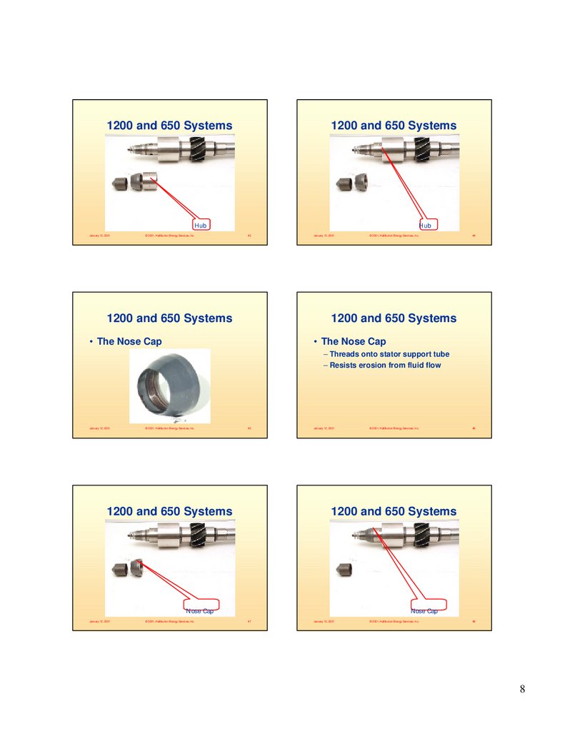
• The Hub
• The Hub
– Slides over key on stator support tube
– Provides a location to place a back-up
wrench when tightening some parts
– Prevents erosion of the pulser
January 12, 2001
© 2001, Halliburton Energy Services, Inc.
41
January 12, 2001
© 2001, Halliburton Energy Services, Inc.
42
7
8.
1200 and 650 Systems1200 and 650 Systems
Hub
January 12, 2001
© 2001, Halliburton Energy Services, Inc.
Hub
43
1200 and 650 Systems
January 12, 2001
© 2001, Halliburton Energy Services, Inc.
44
1200 and 650 Systems
• The Nose Cap
• The Nose Cap
– Threads onto stator support tube
– Resists erosion from fluid flow
January 12, 2001
© 2001, Halliburton Energy Services, Inc.
45
1200 and 650 Systems
January 12, 2001
© 2001, Halliburton Energy Services, Inc.
46
1200 and 650 Systems
Nose Cap
January 12, 2001
© 2001, Halliburton Energy Services, Inc.
Nose Cap
47
January 12, 2001
© 2001, Halliburton Energy Services, Inc.
48
8
9.
1200 and 650 Systems1200 and 650 Systems
• The Poppet
• The Poppet
– Threads onto poppet shaft
– Cause fluid flow restriction when
extended into the orifice
– Resists erosion from fluid flow
January 12, 2001
© 2001, Halliburton Energy Services, Inc.
49
1200 and 650 Systems
January 12, 2001
© 2001, Halliburton Energy Services, Inc.
50
1200 and 650 Systems
Poppet
January 12, 2001
© 2001, Halliburton Energy Services, Inc.
Poppet
51
1200 and 650 Systems
January 12, 2001
© 2001, Halliburton Energy Services, Inc.
52
1200 and 650 Systems
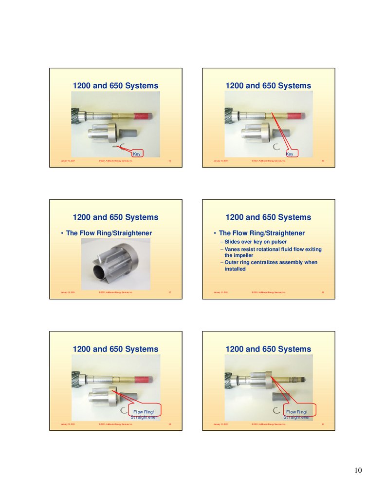
• The Key
• The Key
– Prevents pulser from rotating
– Maintains highside alignment
January 12, 2001
© 2001, Halliburton Energy Services, Inc.
53
January 12, 2001
© 2001, Halliburton Energy Services, Inc.
54
9
10.
1200 and 650 Systems1200 and 650 Systems
Key
January 12, 2001
© 2001, Halliburton Energy Services, Inc.
Key
55
1200 and 650 Systems
January 12, 2001
© 2001, Halliburton Energy Services, Inc.
56
1200 and 650 Systems
• The Flow Ring/Straightener
• The Flow Ring/Straightener
– Slides over key on pulser
– Vanes resist rotational fluid flow exiting
the impeller
– Outer ring centralizes assembly when
installed
January 12, 2001
© 2001, Halliburton Energy Services, Inc.
57
January 12, 2001
© 2001, Halliburton Energy Services, Inc.
1200 and 650 Systems
1200 and 650 Systems
Flow Ring/
Straightener
Flow Ring/
Straightener
January 12, 2001
© 2001, Halliburton Energy Services, Inc.
59
January 12, 2001
© 2001, Halliburton Energy Services, Inc.
58
60
10
11.
1200 and 650 Systems1200 and 650 Systems
• The Snap Ring
• The Snap Ring
– Holds spacer sleeve in place during
assembly
January 12, 2001
© 2001, Halliburton Energy Services, Inc.
61
1200 and 650 Systems
January 12, 2001
© 2001, Halliburton Energy Services, Inc.
1200 and 650 Systems
Snap Ring
January 12, 2001
© 2001, Halliburton Energy Services, Inc.
62
Snap Ring
63
1200 and 650 Systems
January 12, 2001
© 2001, Halliburton Energy Services, Inc.
64
1200 and 650 Systems
• The Spacer Sleeve
• The Spacer Sleeve
– Resists erosion from fluid flow
January 12, 2001
© 2001, Halliburton Energy Services, Inc.
65
January 12, 2001
© 2001, Halliburton Energy Services, Inc.
66
11
12.
1200 and 650 Systems1200 and 650 Systems
Spacer Sleeve
January 12, 2001
© 2001, Halliburton Energy Services, Inc.
Spacer Sleeve
67
1200 and 650 Systems
© 2001, Halliburton Energy Services, Inc.
© 2001, Halliburton Energy Services, Inc.
68
Pulse Generator Assembly
• Pulse Generator Assembly
January 12, 2001
January 12, 2001
• Slimhole and Superslim
69
Slimhole and Superslim
January 12, 2001
© 2001, Halliburton Energy Services, Inc.
70
Slimhole and Superslim
• The Impeller Assembly
• The Impeller Assembly
– Rotates due to mud flow
– Magnetically coupled to pulser’s main
shaft.
– Vane angle related to flow rate
Superslim Impeller
• Slimhole System - 35°, 30° vane angles
Slimhole
Mid Vane Impeller
January 12, 2001
© 2001, Halliburton Energy Services, Inc.
71
• Superslim System 45° vane angle
– Two marine bearings
January 12, 2001
© 2001, Halliburton Energy Services, Inc.
72
12
13.
Slimhole and SuperslimSlimhole and Superslim
Impeller
January 12, 2001
© 2001, Halliburton Energy Services, Inc.
Impeller
73
Slimhole and Superslim
January 12, 2001
© 2001, Halliburton Energy Services, Inc.
74
Slimhole and Superslim
• The Upper Bearing Sleeve
• The Upper Bearing Sleeve
– Supports the impeller’s upper bearing
– Threaded onto the stator support tube
January 12, 2001
© 2001, Halliburton Energy Services, Inc.
75
Slimhole and Superslim
January 12, 2001
© 2001, Halliburton Energy Services, Inc.
76
Slimhole and Superslim
• The Shrouded Stator
• The Shrouded Stator
– Pinned onto the pulser intermediate
case
– Angled vanes deflect fluid flow
– Different vane exit angles dependent
on flow rate
– Shroud centralizes assembly when
installed
January 12, 2001
© 2001, Halliburton Energy Services, Inc.
77
January 12, 2001
© 2001, Halliburton Energy Services, Inc.
78
13
14.
Slimhole and SuperslimSlimhole and Superslim
• The Shrouded Stator Assembly
• The Shrouded Stator Assembly
January 12, 2001
© 2001, Halliburton Energy Services, Inc.
79
Slimhole and Superslim
January 12, 2001
© 2001, Halliburton Energy Services, Inc.
80
Slimhole and Superslim
Shrouded Stator
Assembly
January 12, 2001
© 2001, Halliburton Energy Services, Inc.
Shrouded Stator
Assembly
81
Slimhole and Superslim
January 12, 2001
© 2001, Halliburton Energy Services, Inc.
82
Slimhole and Superslim
• The Pin
• The Pin
– Fits in pin hole on the pulser
intermediate case
– Prevents the shrouded stator from
rotating on the pulser
– Holds shrouded stator and nose cap
(shroud/nose cap-Superslim) on pulser
January 12, 2001
© 2001, Halliburton Energy Services, Inc.
83
January 12, 2001
© 2001, Halliburton Energy Services, Inc.
84
14
15.
Slimhole and SuperslimSlimhole and Superslim
Pin
January 12, 2001
© 2001, Halliburton Energy Services, Inc.
Pin
85
Slimhole and Superslim
January 12, 2001
© 2001, Halliburton Energy Services, Inc.
January 12, 2001
© 2001, Halliburton Energy Services, Inc.
86
Slimhole and Superslim
87
Slimhole and Superslim
January 12, 2001
© 2001, Halliburton Energy Services, Inc.
88
Slimhole and Superslim
• The Split Retainer Ring
• The Split Retainer Ring
– Fits in ring groove on the pulser
intermediate case
– Holds shrouded stator and nose cap
(shroud/nose cap-Superslim) on pulser
January 12, 2001
© 2001, Halliburton Energy Services, Inc.
89
January 12, 2001
© 2001, Halliburton Energy Services, Inc.
90
15
16.
Slimhole and SuperslimSlimhole and Superslim
Split Retainer Ring
January 12, 2001
© 2001, Halliburton Energy Services, Inc.
Split Retainer Ring
91
Slimhole and Superslim
January 12, 2001
© 2001, Halliburton Energy Services, Inc.
January 12, 2001
© 2001, Halliburton Energy Services, Inc.
92
Slimhole and Superslim
93
Slimhole and Superslim
January 12, 2001
© 2001, Halliburton Energy Services, Inc.
94
Slimhole and Superslim
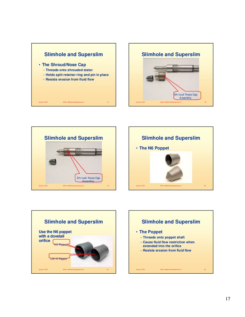
• The Shroud/Nose Cap
January 12, 2001
© 2001, Halliburton Energy Services, Inc.
95
January 12, 2001
© 2001, Halliburton Energy Services, Inc.
96
16
17.
Slimhole and SuperslimSlimhole and Superslim
• The Shroud/Nose Cap
– Threads onto shrouded stator
– Holds split retainer ring and pin in place
– Resists erosion from fluid flow
Shroud/Nose Cap
Assembly
January 12, 2001
© 2001, Halliburton Energy Services, Inc.
97
Slimhole and Superslim
January 12, 2001
© 2001, Halliburton Energy Services, Inc.
98
Slimhole and Superslim
• The N6 Poppet
Shroud/Nose Cap
Assembly
January 12, 2001
© 2001, Halliburton Energy Services, Inc.
99
Slimhole and Superslim
January 12, 2001
© 2001, Halliburton Energy Services, Inc.
100
Slimhole and Superslim
Use the N6 poppet
with a dovetail
orifice
• The Poppet
– Threads onto poppet shaft
– Cause fluid flow restriction when
extended into the orifice
– Resists erosion from fluid flow
N6 Poppet
LW15 Poppet
January 12, 2001
© 2001, Halliburton Energy Services, Inc.
101
January 12, 2001
© 2001, Halliburton Energy Services, Inc.
102
17
18.
Slimhole and SuperslimSlimhole and Superslim
Poppet
January 12, 2001
Poppet
© 2001, Halliburton Energy Services, Inc.
103
Slimhole and Superslim
January 12, 2001
© 2001, Halliburton Energy Services, Inc.
104
Slimhole and Superslim
• The Key
• The Key
– Prevents pulser from rotating
– Maintains highside alignment
January 12, 2001
© 2001, Halliburton Energy Services, Inc.
105
Slimhole and Superslim
© 2001, Halliburton Energy Services, Inc.
106
Slimhole and Superslim
Key
January 12, 2001
January 12, 2001
Key
© 2001, Halliburton Energy Services, Inc.
107
January 12, 2001
© 2001, Halliburton Energy Services, Inc.
108
18
19.
Slimhole and SuperslimSlimhole and Superslim
• The Flow Ring/Straightener
• The Flow Ring/Straightener
– Slides over key on pulser
– Vanes resist rotational fluid flow exiting
the impeller
– Outer ring centralizes assembly when
installed
January 12, 2001
© 2001, Halliburton Energy Services, Inc.
109
Slimhole and Superslim
January 12, 2001
© 2001, Halliburton Energy Services, Inc.
110
Slimhole and Superslim
Flow Ring/Straightener
January 12, 2001
© 2001, Halliburton Energy Services, Inc.
Flow Ring/Straightener
111
Slimhole and Superslim
January 12, 2001
© 2001, Halliburton Energy Services, Inc.
112
Slimhole and Superslim
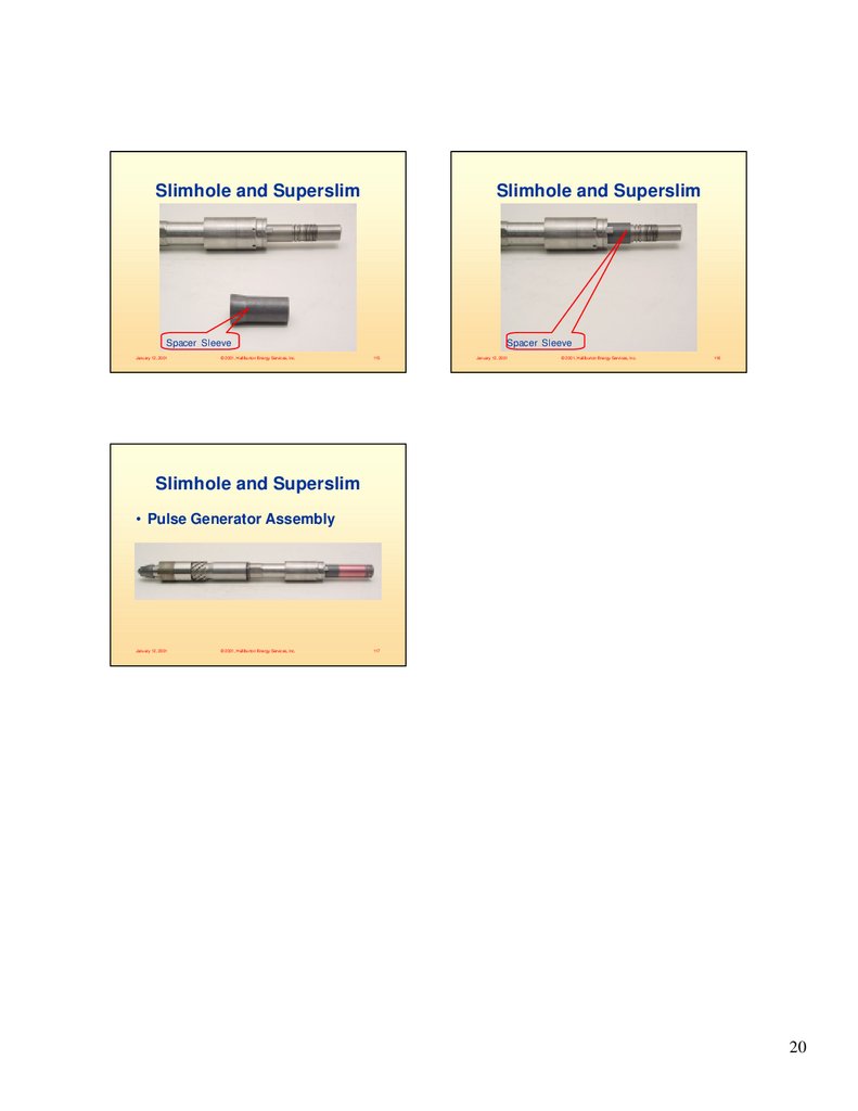
• The Spacer Sleeve
• The Spacer Sleeve
– Resists erosion from fluid flow
January 12, 2001
© 2001, Halliburton Energy Services, Inc.
113
January 12, 2001
© 2001, Halliburton Energy Services, Inc.
114
19
20.
Slimhole and SuperslimSlimhole and Superslim
Spacer Sleeve
January 12, 2001
© 2001, Halliburton Energy Services, Inc.
Spacer Sleeve
115
January 12, 2001
© 2001, Halliburton Energy Services, Inc.
116
Slimhole and Superslim
• Pulse Generator Assembly
January 12, 2001
© 2001, Halliburton Energy Services, Inc.
117
20