 mechanics
Similar presentations:


Fuel System
1.
FUEL SYSTEMЕремеев Александр
ЭВСм 3-2
2.
MAIN PARTS OF THE FUEL SYSTEM• FUEL STORAGE
• PRESSURE REFUELING SYSTEM
• ENGINE FUEL FEED
• APU FUEL FEED
• DEFUELING
• FUEL INDICATING
• FUEL TEMPERATURE INDICATING SYSTEM
• FUEL MEASURING STICK
3.
FUEL SYSTEMPrimary purposes of the fuel system:
• Stores fuel for use by engines and APU
• Supplies fuel to APU
• Supplies fuel to engines
The fuel system has these subsystems:
• Fuel storage
• Pressure fueling
• Engine fuel feed
• APU fuel feed
• Defuel
• Fuel quantity indicating system
• Fuel temperature indication
4.
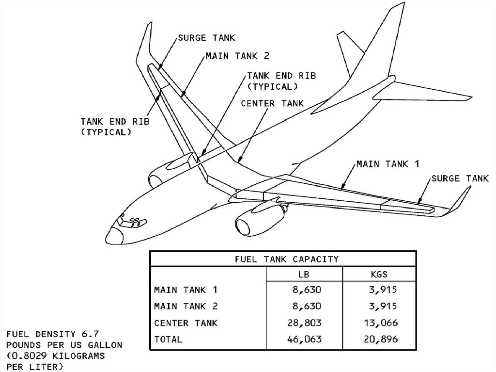
FUEL STORAGEThese tanks store fuel:
• Main tank 1
• Main tank 2
• Center tank
The main tanks are in the wings. Main tank 1 is in the left wing.
Main tank 2 is in the right wing. The center tank is in the fuselage
and the inboard section of each wing.
5.
6.
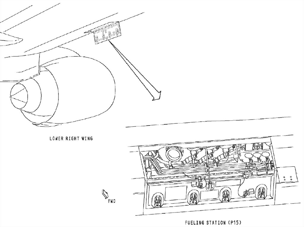
PRESSURE FUELING SYSTEMThe pressure fueling system is used to refuel all tanks and
during fuel transfer from tank to tank.
The fueling station has these components:
• Fueling panel
• Fueling manifold
• Fueling receptacle
• Fueling shutoff valves
7.
8.
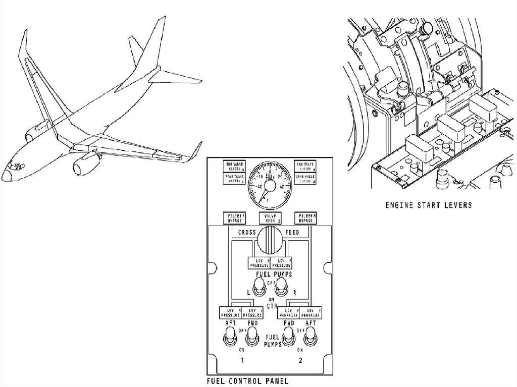
ENGINE FUEL FEEDThe engine fuel feed system supplies fuel from the fuel tanks to
the engines.
It is operated from the fuel control panel and the engine start
levers.
9.
10.
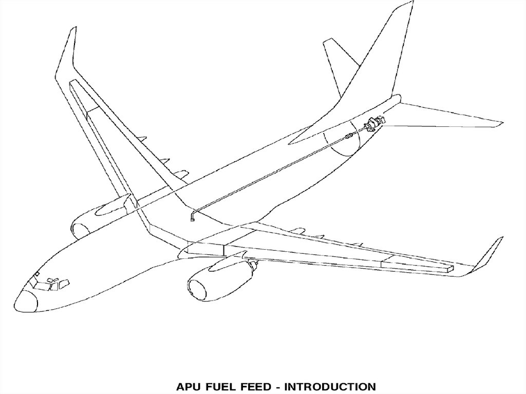
APU FUEL FEEDThis system supplies fuel from any tank to the APU.
The APU fuel feed system has these components:
• APU dc boost pump (Optional)
• APU fuel feed line
• APU fuel feed line shroud
• APU fuel shutoff valve
11.
12.
DEFUELINGThe defuel system removes fuel from the fuel tanks to the refuel
station. The defuel system also permits fuel transfer from one
fuel tank to another.
13.
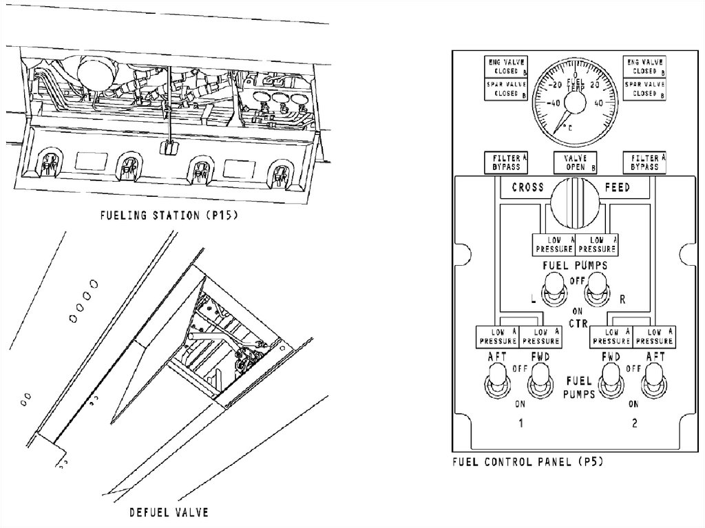
DEFUELINGPressure Defuel
These is used to pressure defuel the tanks:
• Refuel station
• Fuel pumps
• Defuel valve
• Crossfeed valve
Suction Defuel
The defuel valve and refuel station are used to
suction defuel main tank 1 and main tank 2.
14.
15.
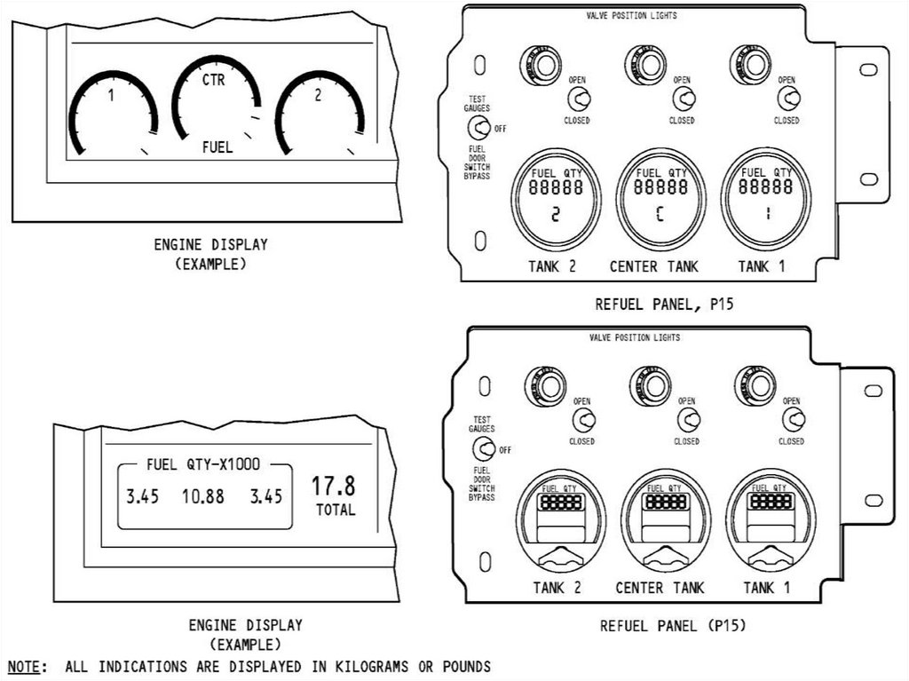
FUEL INDICATINGThe Fuel Quantity Indicating System (FQIS) measures fuel
weight in the fuel tanks. The common display system (CDS) and
the fueling panel show fuel quantity.
The fuel quantity indicating system (FQIS) calculates the fuel
weight in each fuel tank. The fuel quantity of each tank shows
on the common display system (CDS). The fuel quantity
processor unit (FQPU) calculates total fuel weight and supplies
this to the FMCS.
16.
17.
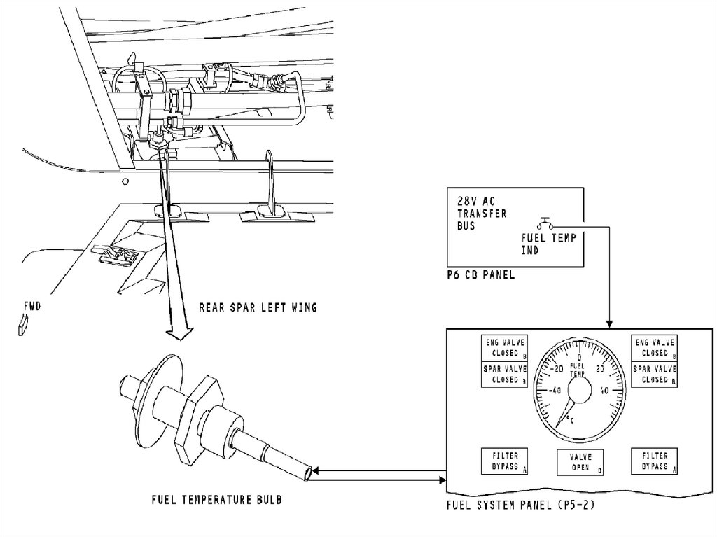
FUEL TEMPERATURE INDICATING SYSTEMPurpose
The fuel temperature indicating system shows fuel temperature in
main tank 1.
Location
The fuel temperature bulb is on the rear spar on main tank 1. The
fuel temperature indicator is on the fuel system panel.
18.
FUEL TEMPERATURE INDICATING SYSTEMComponents
The fuel temperature indicator is a resistance ratiometer
instrument.
The fuel temperature bulb is a resistance unit. The resistance of
the fuel temperature bulb changes with fuel temperature.
19.
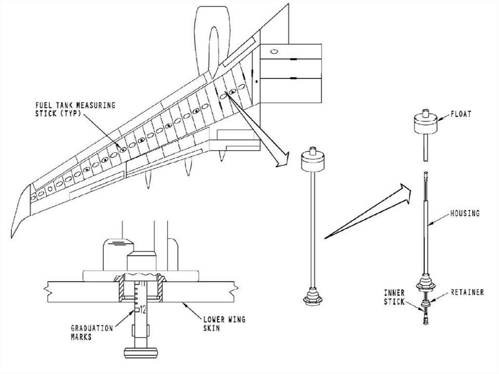
20.
FUEL MEASURING STICKThere are six measuring sticks in main tank 1 and main tank 2.
Each fuel measuring stick is on a fuel tank access door. The fuel
measuring sticks are numbered 3 through 8, from inboard to
outboard.
There are four fuel tank measuring sticks in the center tank. Two
fuel tank measuring sticks are on fuel tank access panels and
two are on the wing skin. The center tank fuel measuring sticks
are numbered 1 and 2, from inboard to outboard.