
 physics
 english
Similar presentations:


")

")


Цепной анализ. Outline
1.
OutlineThese slides contain analyses and results from
1. Dr. Robert Olsen
2. Dr. Richard Abbott
(I put title slides in between to indicate the author)
2.
The following slides were created by Dr. Robert Olsen,Professor Emeritus of Electrical Engineering at WSU and
author of High Voltage Transmission Line Electromagnetics
3.
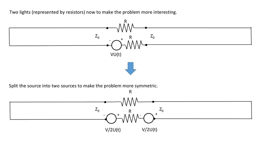
Two lights (represented by resistors) now to make the problem more interesting.R
Z0
+
-
Z0
R
VU(t)
Split the source into two sources to make the problem more symmetric.
R
Z0
-
+
V/2U(t)
R
-
+
V/2U(t)
Z0
4.
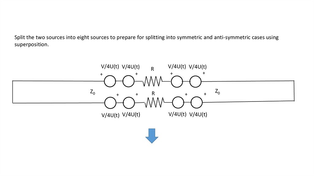
Split the two sources into eight sources to prepare for splitting into symmetric and anti-symmetric cases usingsuperposition.
V/4U(t) V/4U(t)
+
+
Z0
+
+
V/4U(t) V/4U(t)
R
V/4U(t) V/4U(t)
R
+
+
+
+
V/4U(t) V/4U(t)
Z0
5.
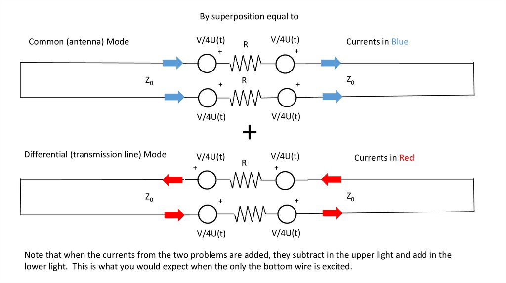
By superposition equal toV/4U(t)
Common (antenna) Mode
+
Z0
+
V/4U(t)
Differential (transmission line) Mode
V/4U(t)
+
Z0
+
V/4U(t)
R
V/4U(t)
+
R
+
R
Currents in Blue
+
Z0
V/4U(t)
V/4U(t)
Currents in Red
+
+
Z0
V/4U(t)
Note that when the currents from the two problems are added, they subtract in the upper light and add in the
lower light. This is what you would expect when the only the bottom wire is excited.
6.
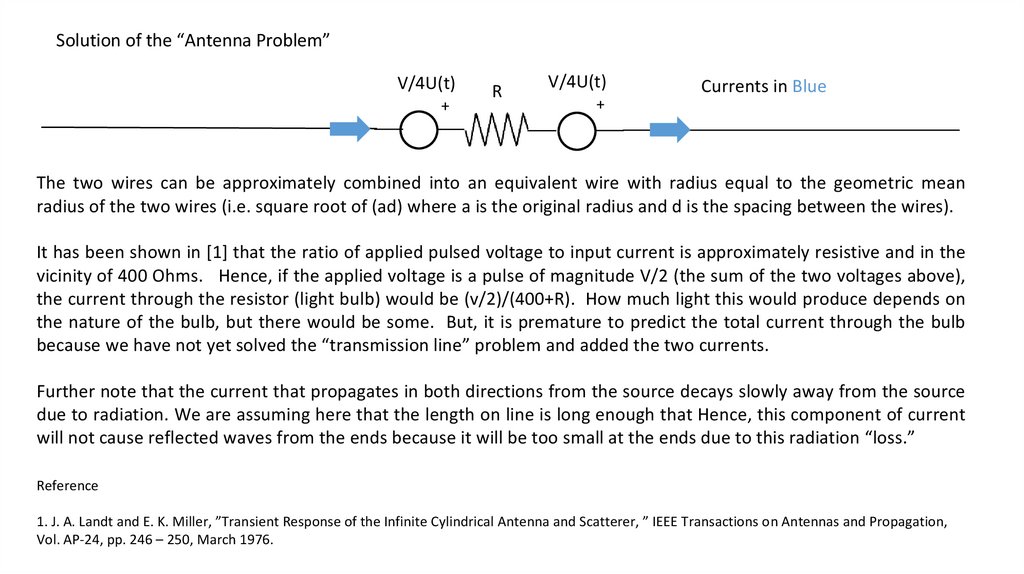
Solution of the “Antenna Problem”V/4U(t)
+
R
V/4U(t)
Currents in Blue
+
The two wires can be approximately combined into an equivalent wire with radius equal to the geometric mean
radius of the two wires (i.e. square root of (ad) where a is the original radius and d is the spacing between the wires).
It has been shown in [1] that the ratio of applied pulsed voltage to input current is approximately resistive and in the
vicinity of 400 Ohms. Hence, if the applied voltage is a pulse of magnitude V/2 (the sum of the two voltages above),
the current through the resistor (light bulb) would be (v/2)/(400+R). How much light this would produce depends on
the nature of the bulb, but there would be some. But, it is premature to predict the total current through the bulb
because we have not yet solved the “transmission line” problem and added the two currents.
Further note that the current that propagates in both directions from the source decays slowly away from the source
due to radiation. We are assuming here that the length on line is long enough that Hence, this component of current
will not cause reflected waves from the ends because it will be too small at the ends due to this radiation “loss.”
Reference
1. J. A. Landt and E. K. Miller, ”Transient Response of the Infinite Cylindrical Antenna and Scatterer, ” IEEE Transactions on Antennas and Propagation,
Vol. AP-24, pp. 246 – 250, March 1976.
7.
Solution of the “Transmission Line Problem”For the Differential (transmission line) Mode, the following equivalent circuit holds for all times that the waves
traveling to the end have not yet been reflected and arrived back at the source
Differential (transmission line) Mode
V/4U(t)
+
Z0
+
V/4U(t)
R
V/4U(t)
Currents in Red
+
+
Z0
V/4U(t)
The initial current would be approximately V divided by (2 Z0 +2R). Given that Z0 for open wire transmission lines
is around 400 Ohms, the “transmission line” component of current would be smaller than the “antenna current.”
The most important thing is that it will almost certainly be different from the antenna current.
8.
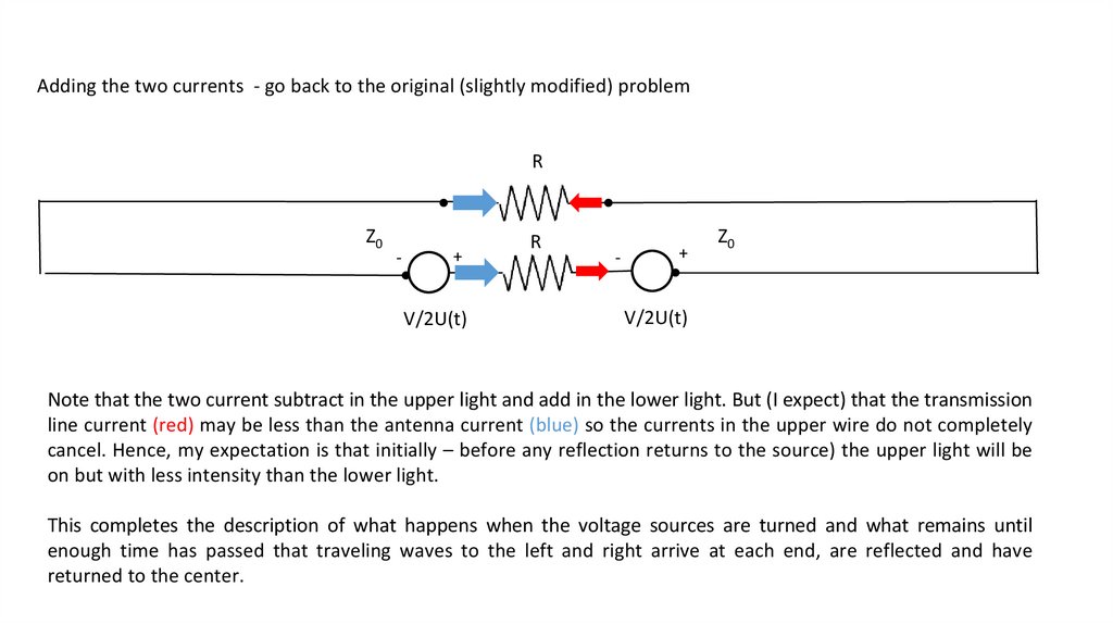
Adding the two currents - go back to the original (slightly modified) problemR
Z0
-
+
V/2U(t)
R
-
+
Z0
V/2U(t)
Note that the two current subtract in the upper light and add in the lower light. But (I expect) that the transmission
line current (red) may be less than the antenna current (blue) so the currents in the upper wire do not completely
cancel. Hence, my expectation is that initially – before any reflection returns to the source) the upper light will be
on but with less intensity than the lower light.
This completes the description of what happens when the voltage sources are turned and what remains until
enough time has passed that traveling waves to the left and right arrive at each end, are reflected and have
returned to the center.
9.
RZ0
-
+
V/2U(t)
R
-
+
Z0
V/2U(t)
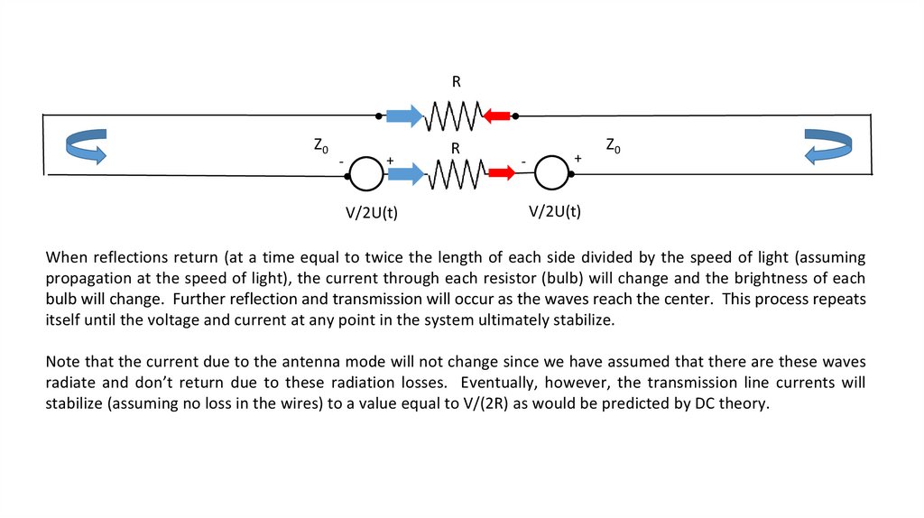
When reflections return (at a time equal to twice the length of each side divided by the speed of light (assuming
propagation at the speed of light), the current through each resistor (bulb) will change and the brightness of each
bulb will change. Further reflection and transmission will occur as the waves reach the center. This process repeats
itself until the voltage and current at any point in the system ultimately stabilize.
Note that the current due to the antenna mode will not change since we have assumed that there are these waves
radiate and don’t return due to these radiation losses. Eventually, however, the transmission line currents will
stabilize (assuming no loss in the wires) to a value equal to V/(2R) as would be predicted by DC theory.
10.
11.
The following analysis was conducted by Dr. Richard Abbott,who works on the Laser Interferometer Gravitational-wave
Observatory (LIGO) at Caltech - he worked on an earlier
version of the problem where the wires are a light-year
long, not a light-second.
12.
Initial AnalysisAssuming the wires you run out on either side are next to each other (not in a big arc) running parallel such that they have a defined physical relationship, AND
assuming the wires were superconducting wires with no resistance, then the ½ lightyear wires would form a transmission line of some characteristic impedance Zo
which would be determined by the wire spacing and wire diameter. If we assume the bulb is purely resistive with no temperature coefficient of resistance that varies as
a function of time or current, and had a resistance equal to twice the magnitude of Zo, and the voltage source is perfect (no output impedance) and the switch is
instantaneous and perfect, then an interesting thing would happen (that’s a lot of assumptions, but they are important to grok the lovely result):
1.
2.
Call the moment where you close the switch time equal to zero, I think the voltage across the bulb would instantly (practically speaking) go to half of the applied voltage.
After a year, there would be a fabulous event where the voltage across the bulb would step up to the full applied voltage.
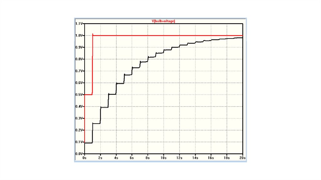
This is all assuming the characteristic impedance of each transmission line is equal to Rbulb/2. If we now space the wires apart such that the characteristic impedance
of the transmission line is 10 times Rbulb/2, another very interesting thing happens:
1.
2.
At t = 0, the bulb turns on to around 1/10th of the applied voltage.
Once a year the voltage will step up a bit, but not linearly. It will look like a stepwise exponential increase over ~20 years or so.
Remember, the brightness of the bulb seems likely to depend on the power, so for the “matched case” at the 1 year mark, the bulb would have twice the voltage, but 4
times the power, which would indeed add to the mysterious effect in terms of the brightness of the bulb.
I ran a simple model and came up with this layman’s result where the red curve is when Zo = Rbulb/2, and the black curve is with 10*Zo.
13.
14.
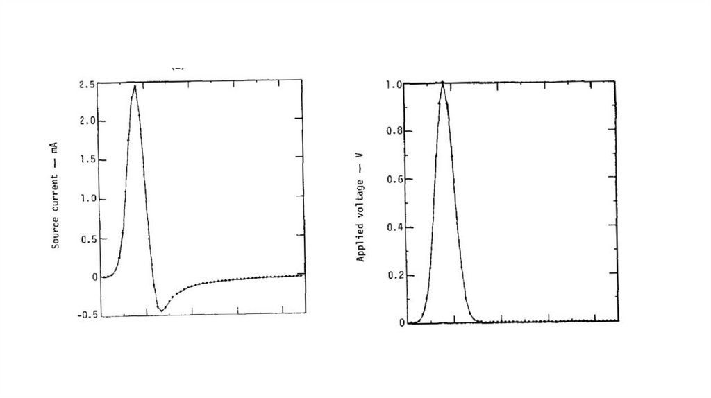
Follow-up simulation and experimentI made a first cut at the experiment yesterday, and the results are fairly good. I qualify this due to the need for a better prototype with less parasitics which takes more
time and care to create. If you think about it, the battery in your original problem statement has a very low source impedance. When I duplicate this in my experiment, I
need to use a signal generator where the output impedance is typically 50 ohms, which masks some of the beauty in the result. A mercury switch would go a long way
to solving that ambiguity, but I don’t have one right now (the old spherical cow postulate)…
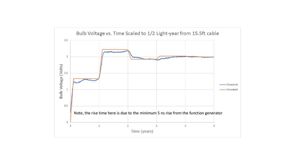
I then simulated the 50 ohm signal generator source and compared it to my observation.
One thing that is obvious so far is that the light comes on immediately at some intermediate value, and doesn’t shut off. What happens as a function of time thereafter
is in reasonable agreement with my simple simulation, but needs refinement in my opinion. Adding loss to the transmission line also steps in a less spectacular
direction.