


 mechanics
Similar presentations:


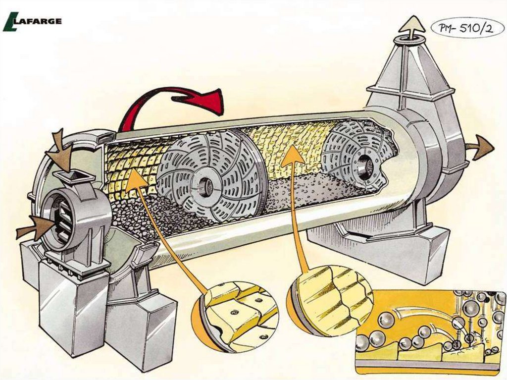
Ball mill dynamics. Grinding
1. Ball Mill Dynamics
GRINDING I – Training Session2. Content
Ball Mill DynamicsContent
• Size reduction mechanism
• Release point and internal dynamics 1st and 2nd
chamber
• 1st chamber liners
• 2nd chamber liners
• Fastening types
• Balls
• Mill head liners
• Material transport
KUJ - July 2012 – Grinding I - 2
3. Content
Ball Mill DynamicsContent
• Size reduction mechanism
• Release point and internal dynamics 1st and 2nd
chamber
• 1st chamber liners
• 2nd chamber liners
• Fastening types
• Balls
• Mill head liners
• Material transport
KUJ - July 2012 – Grinding I - 3
4. 3 mechanisms of size reduction
Ball Mill Dynamics3 mechanisms of size reduction
• Fractures
• Crushing
• Chipping
• Crushing and some fines
• Abrasion
• Fine grinding
KUJ - July 2012 – Grinding I - 4
5. Internal ball dynamics
Ball Mill DynamicsInternal ball dynamics
• Cataracting
• Free fall of the balls
• Emphasis on crushing
Balls Cataracting
Balls Cascading
• Cascading
• Tumbles along charge surface
• Emphasis on fine grinding
Internal dynamics depends on the release point
KUJ - July 2012 – Grinding I - 5
6. Content
Ball Mill DynamicsContent
• Size reduction mechanism
• Release point and internal dynamics 1st and 2nd
chamber
• 1st chamber liners
• 2nd chamber liners
• Fastening types
• Mill head liners
• Material transport
KUJ - July 2012 – Grinding I - 6
7. Release points and grinding
Ball Mill DynamicsRelease points and grinding
Rele ase Poi nts
3
2
1
1
2
3
• Position depends on
three main factors
• % of critical speed
• Liner’s design
• Ball filling rate
Lift Zo ne
Grindi ng
Zone
1 - Casc adi ng (t umbli ng)
2 - Catar acti ng (fr ee fall - max i mpact)
3 - Excessi ve Lift (i mpact on li ner)
Li ner di gs i nto charge.
Some sli p occurs.
KUJ - July 2012 – Grinding I - 7
8. Release point and mill critical speed
Ball Mill DynamicsRelease point and mill critical speed
• Speed of rotation at which centrifugal forces
overcome gravity forces
• At that speed, the balls no longer fall or cascade but ride
on the liners around a full revolution
nc = 42.3 / D
• The best grinding efficiency is reached at 75% of
the critical speed
nopt = 32 / D
• Mill speed is usually between 70 to 78% of nc
KUJ - July 2012 – Grinding I - 8
9. Release points and liners design
Ball Mill DynamicsRelease points and liners design
• Different liners design can
give different release
points and therefore
different grinding actions
KUJ - July 2012 – Grinding I - 9
10. Internal dynamics in first chamber
Ball Mill DynamicsInternal dynamics in first chamber
• Primary grinding of coarse material with large
grinding media (Ø 90-60 mm)
• Aim: high activation of the ball charge for
CRUSHING action
• Good efficiency criteria
• Before intermediate diaphragm:
• 5% of rejects at 2.5 mm
• 15 to 25% of rejects at 0.5mm
KUJ - July 2012 – Grinding I - 10
11. Internal dynamics in second chamber
Ball Mill DynamicsInternal dynamics in second chamber
• Development of a high fineness with small grinding
media (Ø 50-15 mm)
• Aim: ATTRITION and PRESSURE grinding
• Good efficiency criteria
• Before discharge diaphragm
• 5% of rejects at 0.5 mm
• 20 to 30% of rejects at 0.2mm
KUJ - July 2012 – Grinding I - 11
12. Content
Ball Mill DynamicsContent
• Size reduction mechanism
• Release point and internal dynamics 1st and 2nd
chamber
• 1st chamber liners
• 2nd chamber liners
• Fastening types
• Balls
• Mill head liners
• Material transport
KUJ - July 2012 – Grinding I - 12
13. Purpose of a liner’s design
Ball Mill DynamicsPurpose of a liner’s design
• Each liner is designed to ensure:
• Lowest specific energy consumption
• Highest production capacity for a shell design
• Protect mill shell and ensure efficient grinding
action
• With lowest possible specific cost for liners
KUJ - July 2012 – Grinding I - 13
14.
Ball Mill DynamicsKUJ - July 2012 – Grinding I - 14
15. First chamber liners
Ball Mill DynamicsFirst chamber liners
• Activator liners
• Step liner
• Wave liner type “Duolift”
• Step liner tpe “Xlift”
• Step liner with wave profile
KUJ - July 2012 – Grinding I - 15
16. Step liner
Ball Mill DynamicsStep liner
R otation
• Only for first compartments
• Better wear characteristics
• Moderate lift
• Designed for DIN drilled shell
KUJ - July 2012 – Grinding I - 16
17. Single wave & Duolift liners
Ball Mill DynamicsSingle wave & Duolift liners
Early release on
backslope causes
media to slip.
• Only for first compartments
• Single wave
• Negative back slope induces sliding
• Racing is common, wear life is short
• It has good lift
Rotation
• Duolift
• Has a small hump in between lifts to
prevent racing
• Liner’s life is much better
KUJ - July 2012 – Grinding I - 17
18. Installed Duolift liners
Ball Mill DynamicsInstalled Duolift liners
KUJ - July 2012 – Grinding I - 18
19. First chamber - Reminders
Ball Mill DynamicsFirst chamber - Reminders
• Be careful of the appropriate ratio between
Critical speed
Liner lifting action
Ball filling rate
Ball size
1
2
3
Risk of broken liners or high wear level
• Liners must be changed when 60% of their effective
lifting height has worn away
• Consequence 8 to 10% production loss
KUJ - July 2012 – Grinding I - 19
20. Content
Ball Mill DynamicsContent
• Size reduction mechanism
• Release point and internal dynamics 1st and 2nd
chamber
• 1st chamber liners
• 2nd chamber liners
• Fastening types
• Balls
• Mill head liners
• Material transport
KUJ - July 2012 – Grinding I - 20
21. Second chamber liners
Ball Mill DynamicsSecond chamber liners
• Classifying lining with activator profile
• Conventional classifying lining with wave profile
• Wave lining type “Dragpeb” (without classifying effect)
• X-Class
KUJ - July 2012 – Grinding I - 21
22. Purpose of classifying liners
Ball Mill DynamicsPurpose of classifying liners
• Match ball size to particle size (Bond Formula) without
partitions
100 mm
d 20
K
3
W i .
% Vc . D u
Max ball diameter (mm)
d max 20 . 17
10 mm
1 mm
0,01 mm
0,1 mm
1, mm
10, mm
Clinker size D80 (mm)
KUJ - July 2012 – Grinding I - 22
23. Examples of classifying liners
Ball Mill DynamicsExamples of classifying liners
CARMAN LINING
SLEGTEN - MAGOTTEAUX TYPE
NATAL (THIN PROFILE TYPE)
KUJ - July 2012 – Grinding I - 23
24. Classifying liners - issues
Ball Mill DynamicsClassifying liners - issues
• Causes of poor classification
• Liner’s step wear
• Lifting of the charge too low
• wave-like wear profile
• Ball filling ratio > 35%
• Nibs in the charge
• Overfilling of the compartment
• circulating load to high
• Coating
• If no classifying liners
• Dmax / Dmin < 2
KUJ - July 2012 – Grinding I - 24
25. Classifying liner design and mill shell size
Ball Mill DynamicsClassifying liner design and mill shell
size
Mill shell diameter
Ø < 3 meters
3 m< Ø < 4 m
Ø>4m
KUJ - July 2012 – Grinding I - 25
26. Other types of liners : grooved liners
Ball Mill DynamicsOther types of liners : grooved liners
KUJ - July 2012 – Grinding I - 26
27. Other types of liners : Danula or Dam Rings
Ball Mill DynamicsOther types of liners : Danula or Dam Rings
• Where we find it
• Long mills, in the second chamber
• Role
• Keep the grinding media
in the same location
• Disadvantages
• Lagging material transport in the mill
• Balls must be charged in a specific order to ensure proper
ball distribution
KUJ - July 2012 – Grinding I - 27
28. Second chamber - Reminders
Ball Mill DynamicsSecond chamber - Reminders
• Classifying liners
• Causes for poor classification
• Liner step wear
• Lifting of the charge too low
• Liner wave wear
• Ball filling ratio > 35%
• Nibs in the charge
• Overfilling of the compartment
• Circulating load too high
• Coating
• Without classifying liners
• Dmax / Dmin < 2
KUJ - July 2012 – Grinding I - 28
29.
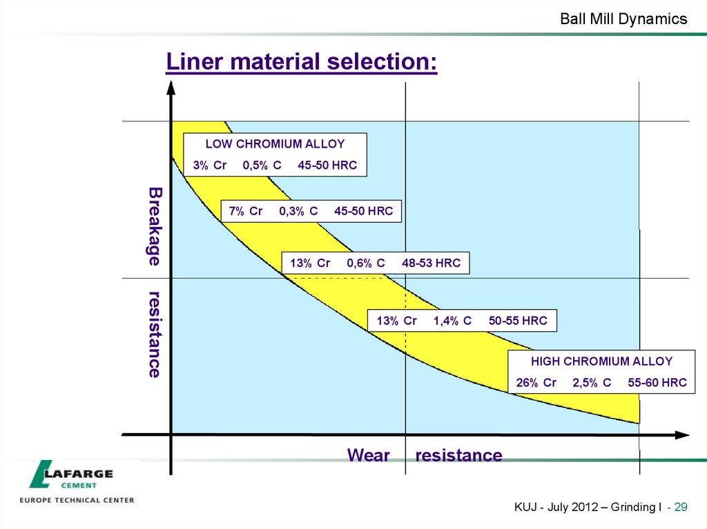
Ball Mill DynamicsLiner material selection:
LOW CHROMIUM ALLOY
3% Cr
0,5% C
Breakage
7% Cr
45-50 HRC
0,3% C
13% Cr
45-50 HRC
0,6% C
48-53 HRC
resistance
13% Cr
1,4% C
50-55 HRC
HIGH CHROMIUM ALLOY
26% Cr
Wear
2,5% C
55-60 HRC
resistance
KUJ - July 2012 – Grinding I - 29
30. Content
Ball Mill DynamicsContent
• Size reduction mechanism
• Release point and internal dynamics 1st and 2nd
chamber
• 1st chamber liners
• 2nd chamber liners
• Fastening types
• Balls
• Mill head liners
• Material transport
KUJ - July 2012 – Grinding I - 30
31. Fastening types
Ball Mill DynamicsFastening types
• Bolted
• Requires a drilling in the mill tube for every plate
• Easy handling during installation and maintenance
KUJ - July 2012 – Grinding I - 31
32. Fastening types
Ball Mill DynamicsFastening types
• Semi-bolted
• Minimum two bolted rows in total
• Requires special tools and experienced fitters
KUJ - July 2012 – Grinding I - 32
33. Fastening types
Ball Mill DynamicsFastening types
• Boltless
• Plates are forced-fitted with positive locking without any bolts
• Requires precise preparation, special tools and very experienced fitters
KUJ - July 2012 – Grinding I - 33
34. Liners’ wear management
Ball Mill DynamicsLiners’ wear management
• Liner wear optimisation
• Avoid metal / metal contact
• Minimise purge duration
• Look for optimal material filling rate
• Bolt holes can result in casting flaws: failures occur
there first.
• Boltless liners wear better, but require careful
installation
KUJ - July 2012 – Grinding I - 34
35. Content
Ball Mill DynamicsContent
• Size reduction mechanism
• Release point and internal dynamics 1st and 2nd
chamber
• 1st chamber liners
• 2nd chamber liners
• Fastening types
• Balls
• Mill head liners
• Material transport
KUJ - July 2012 – Grinding I - 35
36. Balls wear
Ball Mill DynamicsBalls wear
WEAR RATE
FIRST AND SECOND COMPARTMENT
g/t
Portland Cement 96% Clinker + 4% Gypsum (3000 Blaine
)
as well as a typical raw material
20-45
Portland Cement 96% Clinker + 4% Gypsum (4500 Blaine
)
25-50
Cement with 25 to 30% slag or trass (4500 Blaine)
40-60
Cement with ± 70% slag (3000 Blaine)
50-75
Cement with ± 70% slag (4500 Blaine )
70-95
KUJ - July 2012 – Grinding I - 36
37. Content
Ball Mill DynamicsContent
• Size reduction mechanism
• Release point and internal dynamics 1st and 2nd
chamber
• 1st chamber liners
• 2nd chamber liners
• Fastening types
• Mill head liners
• Material transport
KUJ - July 2012 – Grinding I - 37
38. Mill head lining
Ball Mill DynamicsMill head lining
• Conical design
Head liners
• Conical head lining plates on a
conical mill head are exposed to
the high impact of the grinding media.
• Result: high wear on the head lining plates
KUJ - July 2012 – Grinding I - 38
39. Mill head lining
Ball Mill DynamicsMill head lining
• Straight design
(with structure)
Head liners
Structure
• Straight head lining plates on a
conical mill head (realized by a structure) are
protected from high impact of the grinding media.
• Result: less wear on the head lining plates
KUJ - July 2012 – Grinding I - 39
40. Content
Ball Mill DynamicsContent
• Size reduction mechanism
• Release point and internal dynamics 1st and 2nd
chamber
• 1st chamber liners
• 2nd chamber liners
• Fastening types
• Balls
• Mill head liners
• Material transport
KUJ - July 2012 – Grinding I - 40
41. Mass transport
Ball Mill DynamicsMass transport
• Reason for mass transport in the mill shell
• Mill inlet feed pushes the material ahead
• Mill sweeping
• Pumping actions of the partition and discharge wall
• The mill retention time is about 10 to 15 minutes in
closed circuit
(20-30 min in open circuit)
KUJ - July 2012 – Grinding I - 41
42. Material filling ratio
Ball Mill DynamicsMaterial filling ratio
• Definition
Material filling ratio
volume of material
volume of voids in the charge
(In practice, it is evaluated with the level of material above or below the charge surface)
• Optimise filling to maximise grinding
Breakage vs Material Filling Ratio
Relative Absolute Breakage Rate, Sfc/K
0.030
35 %/45 %/50 % in betwe en
40 %
30 %
0.025
20 %
0.020
Optim um Ra nge
0.6 to 1.1
0.015
0.0
0.2
0.4
0.6
0.8
1.0
1.2
1.4
Material Filli ng Ratio, U
KUJ - July 2012 – Grinding I - 42
43. Grinding vs. filling
Ball Mill DynamicsGrinding vs. filling
• Interparticle grinding
Nip or Contact points where
crushing takes place
For filling ratios less than 0.6
there's steel to steel contact
and no grinding
occurs when the voids
space is properly filled
• The collision of balls
Voids where interparticle
grinding takes place
causes momentary high
pressure compression
For filling ratios greater than
1,1 balls are pushed apart,
cushioning impact
KUJ - July 2012 – Grinding I - 43
44. Mill bypass
Ball Mill DynamicsMill bypass
• Ball charge expands when
overloaded
• In the extreme, a stream of
material “bypass” the load
at his toe
Normal Load Level
Expanded Load
Mill Bypas s
• Consequences
• Chips and spitzers will
accumulate at the discharge end
• Once past a critical point,
production drops off
KUJ - July 2012 – Grinding I - 44
45. How to manage the material filling rate
Ball Mill DynamicsHow to manage the material filling rate
• Ball charge design
• The charge permeability depends on ball size
• Circulating load level
• Tuning of the partition drain effect
KUJ - July 2012 – Grinding I - 45