


 industry
Similar presentations:


Steel DC TIG welding training material. Version 1.0
1.
Steel DC TIG weldingtraining material
Version 1.0
4-2002 1
2.
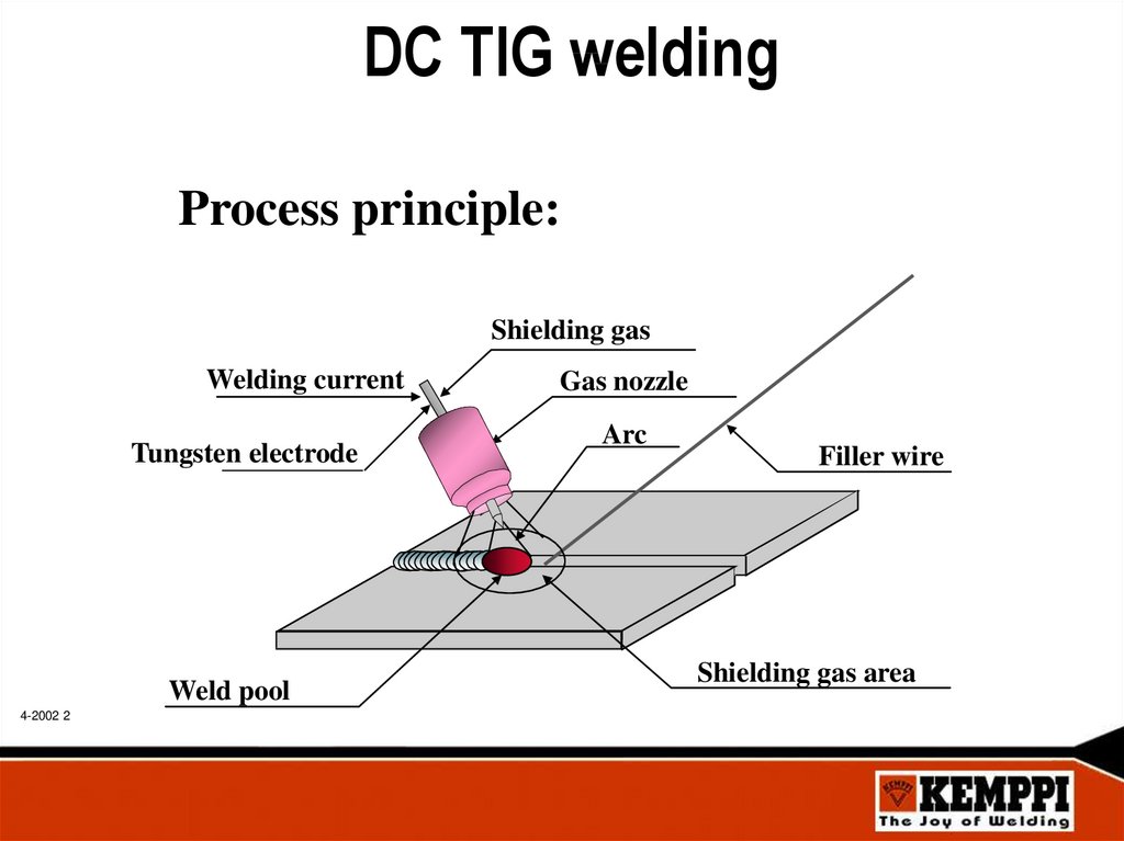
DC TIG weldingProcess principle:
Shielding gas
Welding current
Tungsten electrode
Weld pool
4-2002 2
Gas nozzle
Arc
Filler wire
Shielding gas area
3.
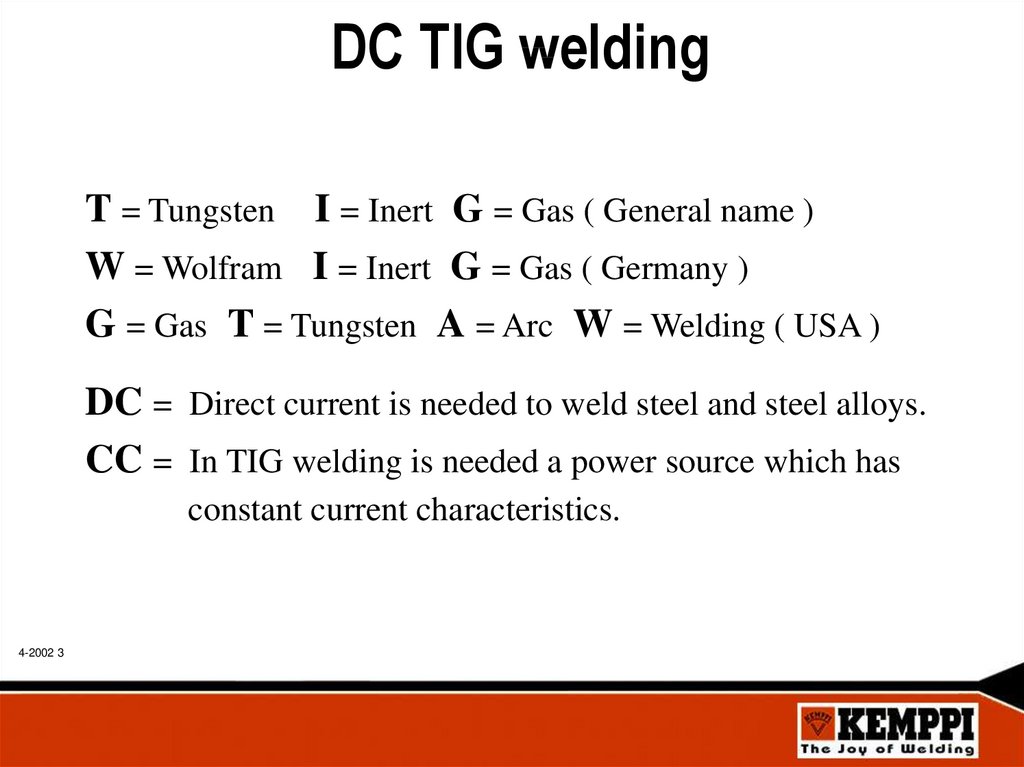
DC TIG weldingT = Tungsten I = Inert G = Gas ( General name )
W = Wolfram I = Inert G = Gas ( Germany )
G = Gas T = Tungsten A = Arc W = Welding ( USA )
DC = Direct current is needed to weld steel and steel alloys.
CC = In TIG welding is needed a power source which has
constant current characteristics.
4-2002 3
4.
TIG benefits and features4-2002 4
Good visibility to the weld pool, no smoke or welding slag.
“Easy” to learn.
High quality, clean weld result, no spatters.
Welding of thin materials, min current 3 A.
Welding without filler material is possible.
Energy and amount of filler material is not related together.
Good profile of weld seam in all positions.
Narrow and concentrated arc form with controlled penetration.
Versatile use of process, welding can also be mechanized.
Special functions & equipment:
Minilog
Pulsed TIG welding
Foot pedal
Special TIG torches
5.
TIG process limitationsLower productivity than in MIG / MAG welding.
Sensitive for base or filler material impurity, rust, oil, moisture, paint.
Welding technique more demanding than in MMA or MIG / MAG.
Welding outdoors needs special arrangements for shielding gas.
TIG torch components vary according of needs:
Tungsten electrode diameter
Gas nozzle or gas lens
Collet body and collet
• Tungsten electrode needs maintenance:
Correct shape of grinding in electrode head
Correct type ( alloy ) and diameter
• Manual filler material feeding
4-2002 5
6.
TIG applicationsTIG is suitable in steel welding cases where quality and visual appearance
of weld seam are the most important matters.
• With TIG can be welded all weldable steels and steel alloys.
• General applications for seams which need good visual look.
Metal furniture, machine building, bicycles etc.
• Chemical industry needs smooth weld profiles.
Pipes, tanks, etc.
• Aviation and air force industry use TIG welding for it´s reliability.
• Thin sheet industry
Automotive and car industry, bus industry, etc.
• Repair welding of all kind of steel products.
Machinery, maintenance, etc.
• X-ray quality root passes.
4-2002 6
7.
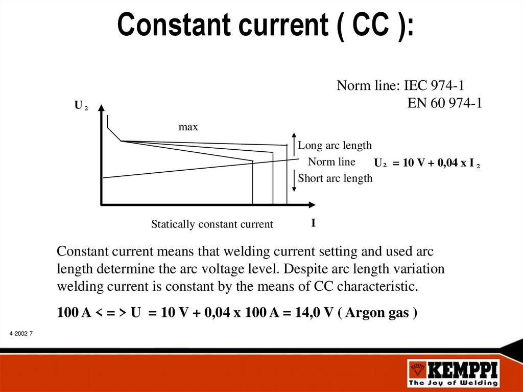
Constant current ( CC ):Norm line: IEC 974-1
EN 60 974-1
U²
max
Long arc length
Norm line
U ² = 10 V + 0,04 x I ²
Short arc length
Statically constant current
I
Constant current means that welding current setting and used arc
length determine the arc voltage level. Despite arc length variation
welding current is constant by the means of CC characteristic.
100 A < = > U = 10 V + 0,04 x 100 A = 14,0 V ( Argon gas )
4-2002 7
8.
DC TIG polarityOn steel TIG welding is used DC current, electrode connected to -pole ( Straight
polarity, DCEN ).
This optimize heat deviation between electrode and base material.
Benefits:
• Small electrode diameter can be used.
• Penetration is deep and narrow.
• Arc is stable and concentrated.
• Low temperature to the TIG torch.
-
30 %
Energy
+
70 %
4-2002 8
-
+
DC Power
Source
9.
High frequency ignition ( HF )• In steel welding DC TIG arc is recommended to ignite with high Voltage
spark ( 10 kV ) ignition.
• High Voltage spark is ionizing shielding gas electrically conductive, which
utilize TIG arc ignition without mechanical contact between electrode head
and base material.
Benefits:
• Good quality ignition without risk of base material or electrode head
contamination.
• All adjustable TIG welding parameters are located to the HF unit.
• High X-ray quality weld result with controlled start and ending of welding.
• Exact ignition point
4-2002 9
10.
Contact ignitionDC TIG arc can also be ignited by contacting
with tungsten electrode to the base material
and lifting it off ( Lift arc ).
I
Arc ignition
• During contact power source give low pilot
current to eliminate electrode sticking
Pilot current
• Ignition happens so fast that sharpened
electrode head is not damaged.
• After ignition welding current goes automatically to the set current value.
Benefits:
• For environments where high frequency ignition can produce EMC
disturbances ( nuclear, computers, robots, etc ).
• Smaller and lighter welding unit which is more portable to use
• Cheap and “easy to use” equipment.
4-2002 10
t
11.
Welding preparations• Steel is having normally on it´s surface slag coming from the material hot rolling
manufacturing process, also rust or primary paint.
• Plates or pipes can also be cutted with plasma or by oxygen acetylene flame cutting.
• Before TIG welding all impurities must be removed.
• Grooves and also 20 mm from welding joint surface on both sides must be cleaned
with grinding disk or machine file to guarantee good weld quality.
Steel plates and pipes must be dry and clean from the welding area before
welding.
4-2002 11
12.
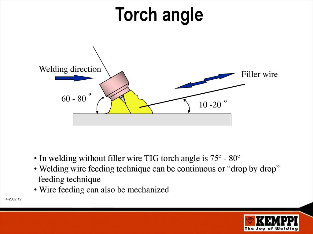
Torch angleWelding direction
60 - 80
Filler wire
o
10 -20
o
• In welding without filler wire TIG torch angle is 75º - 80º
• Welding wire feeding technique can be continuous or “drop by drop”
feeding technique
• Wire feeding can also be mechanized
4-2002 12
13.
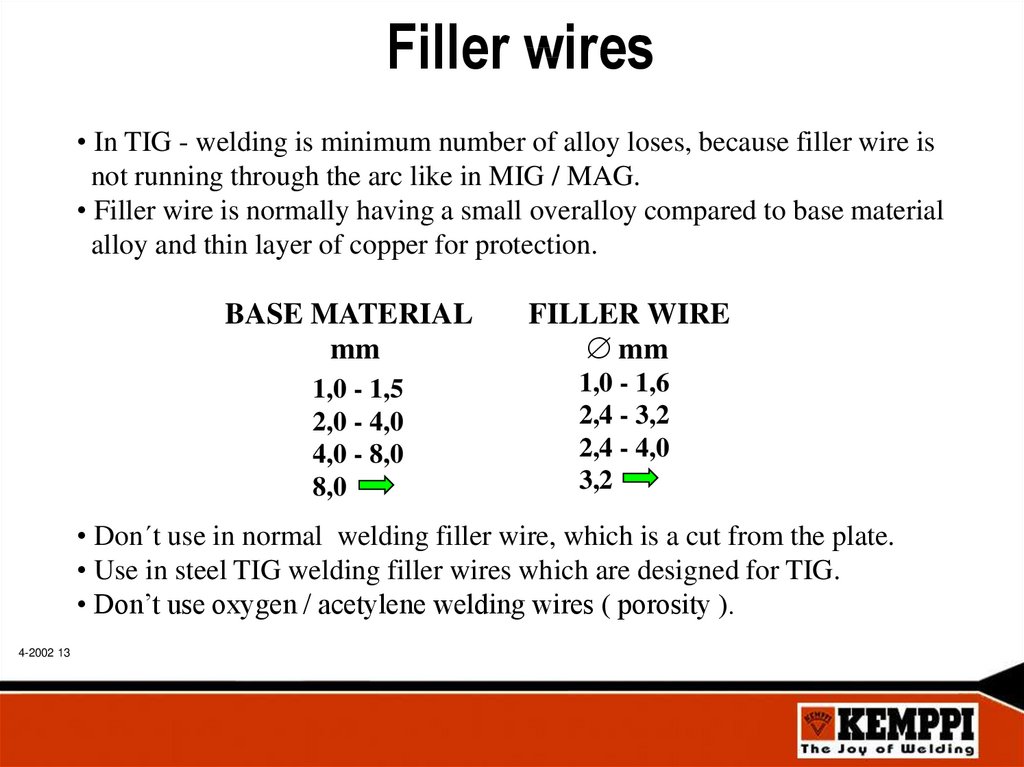
Filler wires• In TIG - welding is minimum number of alloy loses, because filler wire is
not running through the arc like in MIG / MAG.
• Filler wire is normally having a small overalloy compared to base material
alloy and thin layer of copper for protection.
BASE MATERIAL
mm
1,0 - 1,5
2,0 - 4,0
4,0 - 8,0
8,0
FILLER WIRE
mm
1,0 - 1,6
2,4 - 3,2
2,4 - 4,0
3,2
• Don´t use in normal welding filler wire, which is a cut from the plate.
• Use in steel TIG welding filler wires which are designed for TIG.
• Don’t use oxygen / acetylene welding wires ( porosity ).
4-2002 13
14.
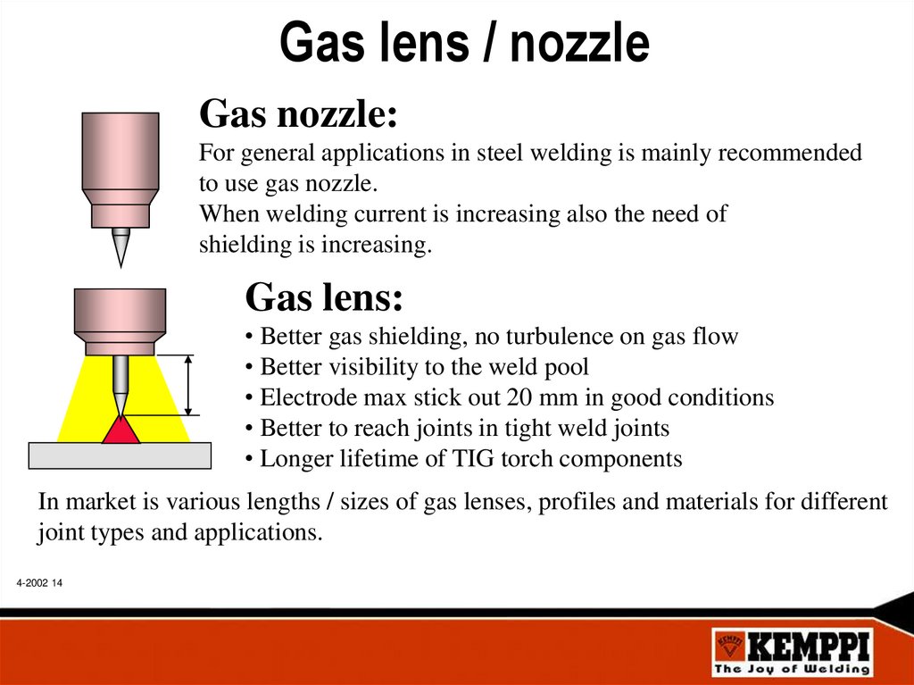
Gas lens / nozzleGas nozzle:
For general applications in steel welding is mainly recommended
to use gas nozzle.
When welding current is increasing also the need of
shielding is increasing.
Gas lens:
• Better gas shielding, no turbulence on gas flow
• Better visibility to the weld pool
• Electrode max stick out 20 mm in good conditions
• Better to reach joints in tight weld joints
• Longer lifetime of TIG torch components
In market is various lengths / sizes of gas lenses, profiles and materials for different
joint types and applications.
4-2002 14
15.
Gas nozzle / lens inside diameterGas nozzle / lens n:o is coming from 1/16” ( 1,5875mm )
Ex. diameter on n:o 5 is 5 x 1,5875 mm = 7,9 mm
Gas nozzle / lens inside diameter must be in minimum as big as
weld pool.
n:o 5
Gas nozzle / lens inside diameter must be in minimum 4 times
electrode diameter.
NOTICE !
Large nozzle / lens diameter guarantees minimum risk for porosity.
4-2002 15
16.
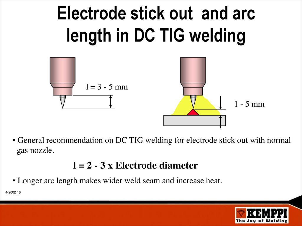
Electrode stick out and arclength in DC TIG welding
l = 3 - 5 mm
1 - 5 mm
• General recommendation on DC TIG welding for electrode stick out with normal
gas nozzle.
l = 2 - 3 x Electrode diameter
• Longer arc length makes wider weld seam and increase heat.
4-2002 16
17.
Electrode stick out and arc lengthMax stick out with nozzle
Max arc length with nozzle
5
Arc length depends on used current and joint type as follows:
• Fillet joints collect gas, electrode max stick out distance 5,0 mm.
• Corner joints separate gas, electrode max stick out distance 3,0 mm.
4-2002 17
3
18.
Steel DC TIG gas flowl / min 16
14
12
10
8
6
4
0
4-2002 18
50
100
150
200
250
300
Flow of shielding gas is depending lot of welding conditions:
• Inside / outside welding ( wind effect )
• TIG torch accessories nozzle or lens ( diameters )
• Base material cleaning etc.
A
19.
Electrode diameter selectionElectrode
diameter
1,6 mm
2,4 mm
3,2 mm
4,0 mm
Gas nozzle
no:
4-5
5-6
6-8
6 - 10
Gas
flow
5 - 8 l / min
6 - 10 l / min
8 - 12 l / min
8 - 14 l / min
Current
range
20 - 140 A
100 - 250 A
150 - 320 A
200 - 500 A
NOTICE !
Different alloys of TIG tungsten electrodes are having different optimum
operation ranges in Amperes.
4-2002 19
20.
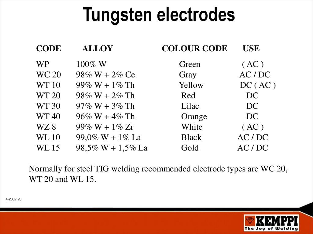
Tungsten electrodesCODE
WP
WC 20
WT 10
WT 20
WT 30
WT 40
WZ 8
WL 10
WL 15
ALLOY
100% W
98% W + 2% Ce
99% W + 1% Th
98% W + 2% Th
97% W + 3% Th
96% W + 4% Th
99% W + 1% Zr
99,0% W + 1% La
98,5% W + 1,5% La
COLOUR CODE
Green
Gray
Yellow
Red
Lilac
Orange
White
Black
Gold
USE
( AC )
AC / DC
DC ( AC )
DC
DC
DC
( AC )
AC / DC
AC / DC
Normally for steel TIG welding recommended electrode types are WC 20,
WT 20 and WL 15.
4-2002 20
21.
Electrode sharpeningL = 1...5 x d
d
L
d = 2,4 mm
L = 5 x 2,4 mm = 12,0 mm
• Correct electrode diameter depends on used welding current
• Used sharpening length depends on used welding current
• Grind sharpening angle so that grinding scratches are longitudinal.
4-2002 21
22.
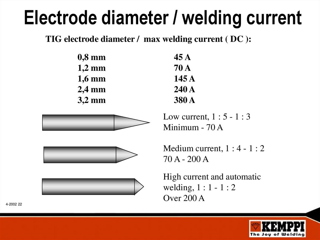
Electrode diameter / welding currentTIG electrode diameter / max welding current ( DC ):
0,8 mm
1,2 mm
1,6 mm
2,4 mm
3,2 mm
45 A
70 A
145 A
240 A
380 A
Low current, 1 : 5 - 1 : 3
Minimum - 70 A
Medium current, 1 : 4 - 1 : 2
70 A - 200 A
High current and automatic
welding, 1 : 1 - 1 : 2
Over 200 A
4-2002 22
23.
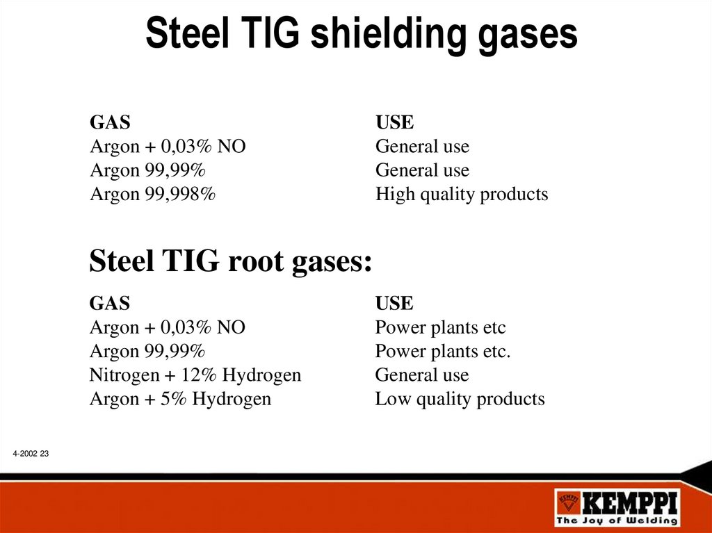
Steel TIG shielding gasesGAS
Argon + 0,03% NO
Argon 99,99%
Argon 99,998%
USE
General use
General use
High quality products
Steel TIG root gases:
GAS
Argon + 0,03% NO
Argon 99,99%
Nitrogen + 12% Hydrogen
Argon + 5% Hydrogen
4-2002 23
USE
Power plants etc
Power plants etc.
General use
Low quality products
24.
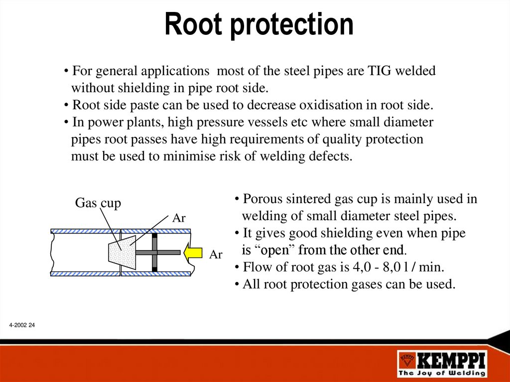
Root protection• For general applications most of the steel pipes are TIG welded
without shielding in pipe root side.
• Root side paste can be used to decrease oxidisation in root side.
• In power plants, high pressure vessels etc where small diameter
pipes root passes have high requirements of quality protection
must be used to minimise risk of welding defects.
Gas cup
Ar
4-2002 24
• Porous sintered gas cup is mainly used in
welding of small diameter steel pipes.
• It gives good shielding even when pipe
is “open” from the other end.
Ar
• Flow of root gas is 4,0 - 8,0 l / min.
• All root protection gases can be used.
25.
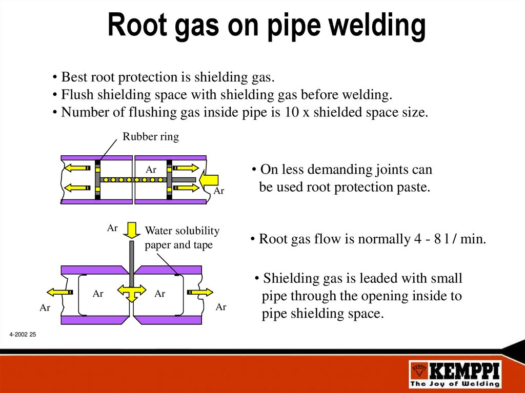
Root gas on pipe welding• Best root protection is shielding gas.
• Flush shielding space with shielding gas before welding.
• Number of flushing gas inside pipe is 10 x shielded space size.
Rubber ring
Ar
Ar
Ar
Ar
Ar
4-2002 25
Water solubility
paper and tape
Ar
Ar
• On less demanding joints can
be used root protection paste.
• Root gas flow is normally 4 - 8 l / min.
• Shielding gas is leaded with small
pipe through the opening inside to
pipe shielding space.
26.
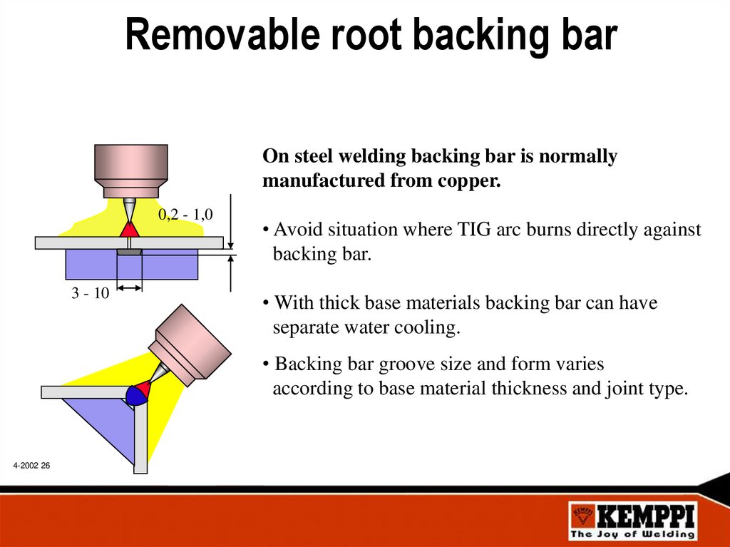
Removable root backing barOn steel welding backing bar is normally
manufactured from copper.
0,2 - 1,0
3 - 10
• Avoid situation where TIG arc burns directly against
backing bar.
• With thick base materials backing bar can have
separate water cooling.
• Backing bar groove size and form varies
according to base material thickness and joint type.
4-2002 26
27.
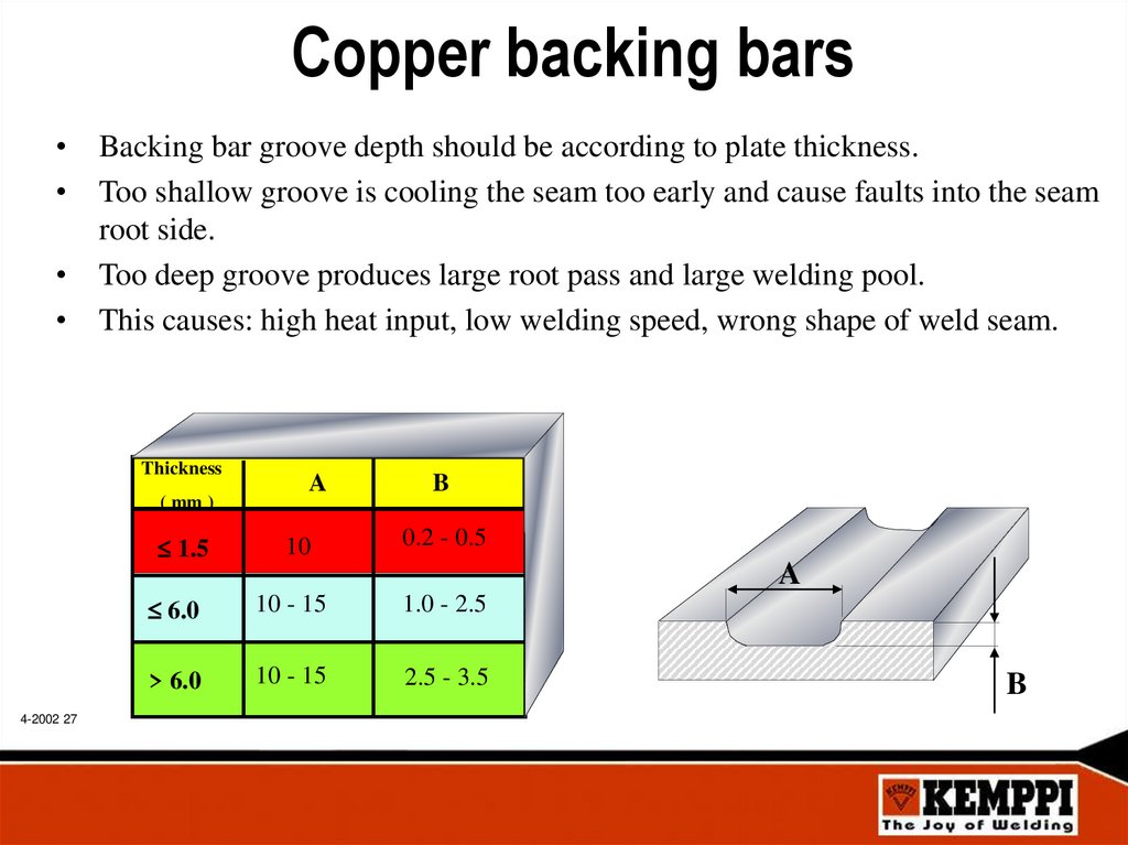
Copper backing bars• Backing bar groove depth should be according to plate thickness.
• Too shallow groove is cooling the seam too early and cause faults into the seam
root side.
• Too deep groove produces large root pass and large welding pool.
• This causes: high heat input, low welding speed, wrong shape of weld seam.
Thickness
( mm )
1.5
4-2002 27
A
10
B
0.2 - 0.5
A
6.0
10 - 15
1.0 - 2.5
> 6.0
10 - 15
2.5 - 3.5
B
28.
Benefits and task of backing bars4-2002 28
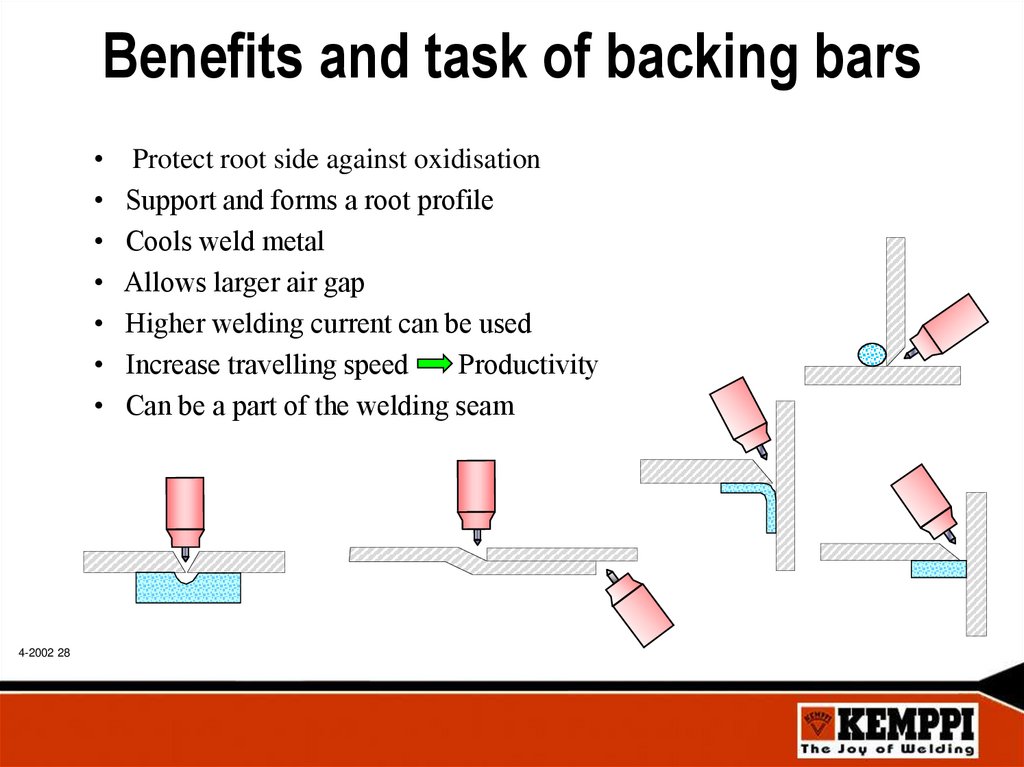
Protect root side against oxidisation
Support and forms a root profile
Cools weld metal
Allows larger air gap
Higher welding current can be used
Increase travelling speed
Productivity
Can be a part of the welding seam
29.
Pre gas / Post flow functionsDuring Pre gas function shielding gas is flowing to the welding area
regulated time before ignition.
Benefits:
• Stable gas flow on ignition moment
• “Flushing” of long TIG torch gas hose free of air
• Groove area cleaning of air
During gas post flow time hot tungsten electrode and the end of weld seam
are cooled inside shielding gas protection after arc has cut off.
Benefits:
• Good electrode re ignition
• No oxidization on tungsten electrode
• Longer electrode sharpened head lifetime
• Smaller risk for welding defects
4-2002 29
30.
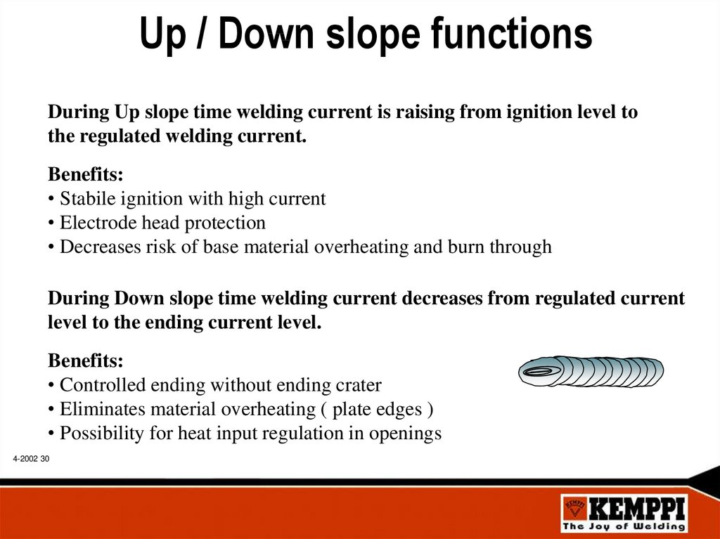
Up / Down slope functionsDuring Up slope time welding current is raising from ignition level to
the regulated welding current.
Benefits:
• Stabile ignition with high current
• Electrode head protection
• Decreases risk of base material overheating and burn through
During Down slope time welding current decreases from regulated current
level to the ending current level.
Benefits:
• Controlled ending without ending crater
• Eliminates material overheating ( plate edges )
• Possibility for heat input regulation in openings
4-2002 30
31.
Steel joint formsManual TIG
welding with filler
Manual TIG
no filler
S = 4 - 8 mm
60°
2,0 - 3,0 mm
S = > 4 mm
4-2002 31
S = > 4 mm
S = 3 - 15 mm
60°
1,5
0 mm
S = > 4 mm
0 -1,5
0 mm
0 mm
1,0 - 3,0 mm
1,5 - 3,0
S = < 4 mm
S = < 3 mm
S = < 3 mm
0 -1,5
Mechanized
TIG welding
0 mm
1,5
0 mm
1,5
32.
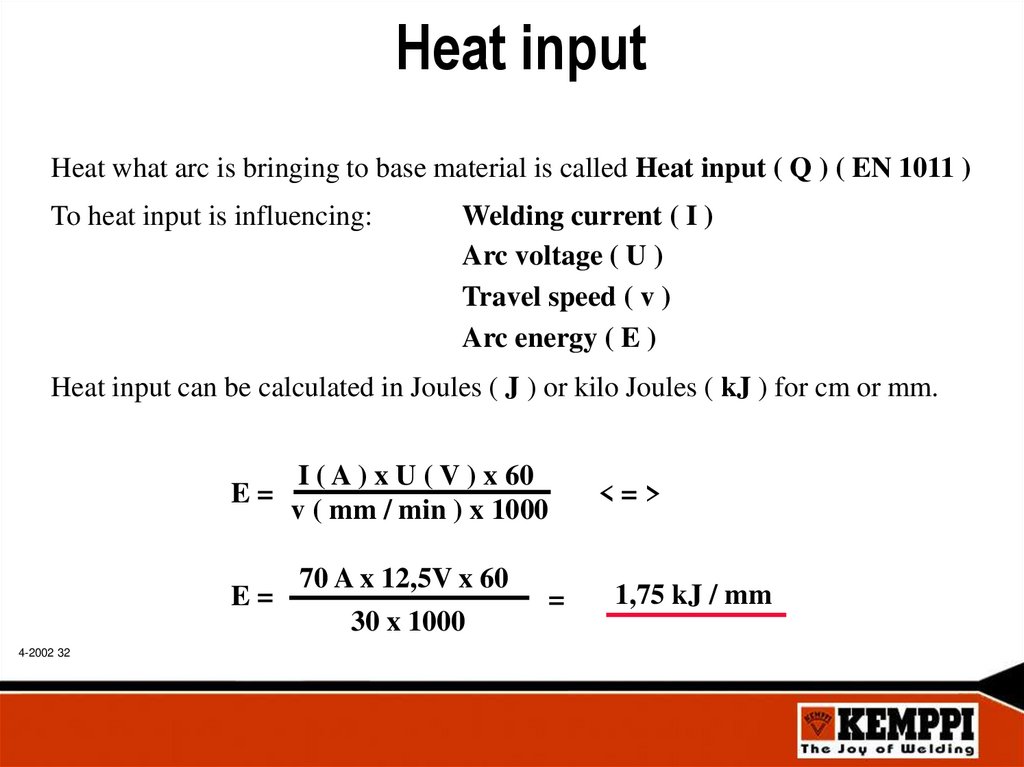
Heat inputHeat what arc is bringing to base material is called Heat input ( Q ) ( EN 1011 )
To heat input is influencing:
Welding current ( I )
Arc voltage ( U )
Travel speed ( v )
Arc energy ( E )
Heat input can be calculated in Joules ( J ) or kilo Joules ( kJ ) for cm or mm.
E=
E=
4-2002 32
I ( A ) x U ( V ) x 60
v ( mm / min ) x 1000
70 A x 12,5V x 60
30 x 1000
=
<=>
1,75 kJ / mm
33.
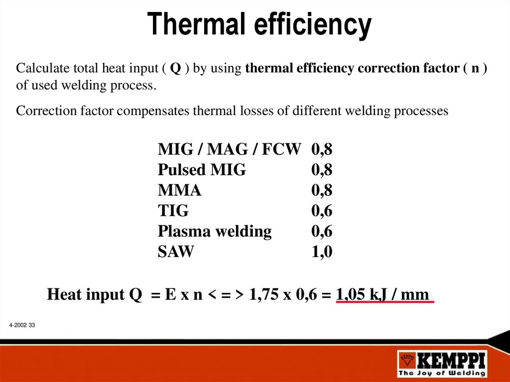
Thermal efficiencyCalculate total heat input ( Q ) by using thermal efficiency correction factor ( n )
of used welding process.
Correction factor compensates thermal losses of different welding processes
MIG / MAG / FCW
Pulsed MIG
MMA
TIG
Plasma welding
SAW
0,8
0,8
0,8
0,6
0,6
1,0
Heat input Q = E x n < = > 1,75 x 0,6 = 1,05 kJ / mm
4-2002 33
34.
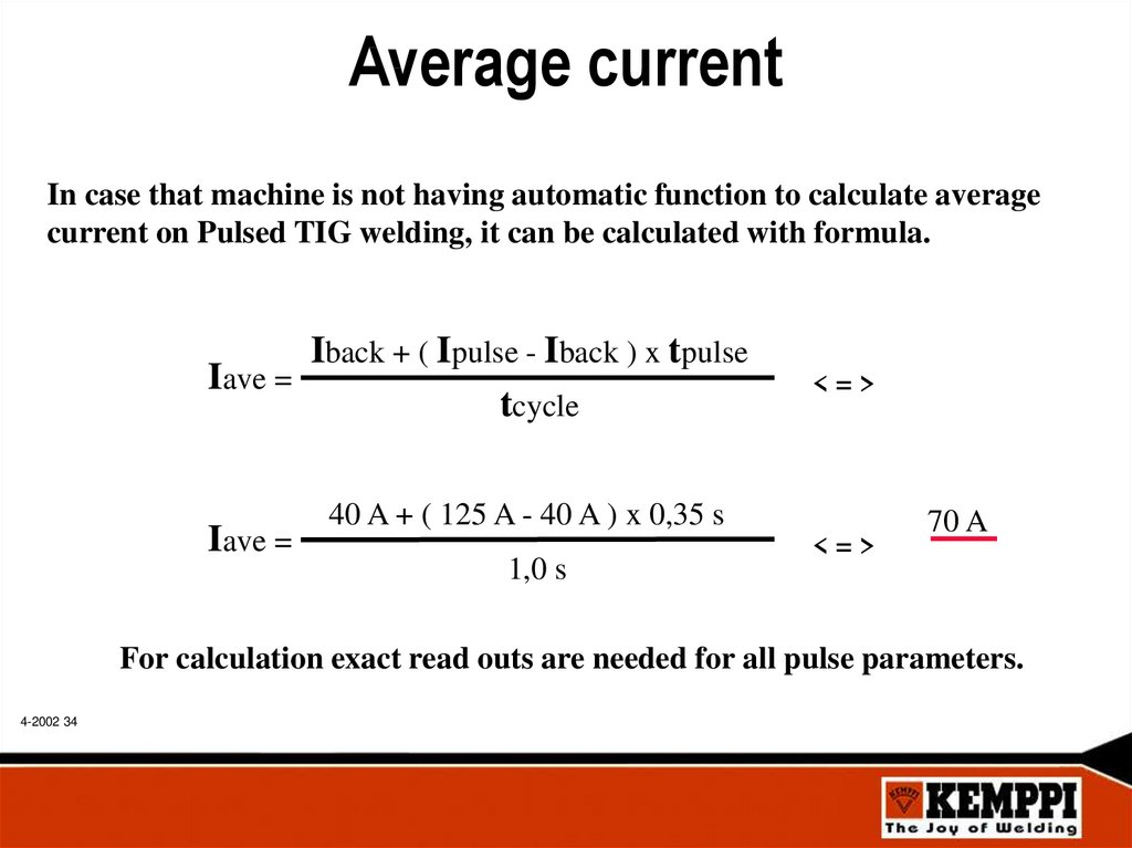
Average currentIn case that machine is not having automatic function to calculate average
current on Pulsed TIG welding, it can be calculated with formula.
Iback + ( Ipulse - Iback ) x tpulse
Iave =
tcycle
Iave =
<=>
40 A + ( 125 A - 40 A ) x 0,35 s
1,0 s
<=>
70 A
For calculation exact read outs are needed for all pulse parameters.
4-2002 34
35.
TIG treatmentTIG treatment is used in cases where MIG / MAG seam needs:
• improve dynamically loaded welded constructions strength
• Used mainly with high strength steels ( Hardox, Weldox, Raex )
• visual reasons, wrong weld profile ( convex )
• repair of weld joint failures ( undercut )
• to avoid grinding
TIG treatment is mainly used:
• heavy machinery and thick materials
• mining machinery
• diggers & earth movers
• lifting brackets
• to improve weld joint impact strength
a-size 6 mm, ideal MIG weld profile
TIG treatment without filler metal
4-2002 35
12
12
TIG treatment
& repair
36.
Steel Pulsed TIG weldingIn Pulsed TIG welding current changes according
set frequency between higher pulse current and
lower background current.
I
Ip
Iave
Ib
tp
tc
Iave = Average current
t c = Cycle time / f = Frequency
t p = Pulse time
I p = Pulse current
I b = Background current
t
Modern TIG machine calculates automatically average current from pulse parameters.
4-2002 36
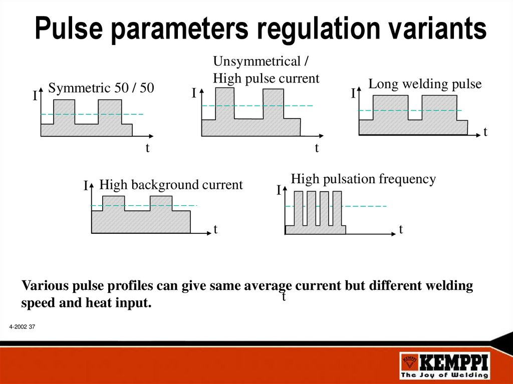
37.
Pulse parameters regulation variantsI
Symmetric 50 / 50
Unsymmetrical /
High pulse current
I
I
Long welding pulse
t
t
t
I High background current
t
I
High pulsation frequency
t
Various pulse profiles can give same average current but different welding
t
speed and heat input.
4-2002 37
38.
Rapid pulse ( RP )Pulsed TIG welding is divided to two main section:
• Frequency from 50 to 500 Hz ( 0,02 s - 0,002 s cycle time)
• High pulse current ensures deep penetration
• Low background current makes weld pool smaller
• Synergic Rapid Pulse TIG makes control easier
• Wire feeding can be continuos or “ drop by drop “ technique
• Low heat input
• Arc looks like continuous TIG welding
• Sound level is higher ( due high pulse frequency )
• For thin plates ( max 3,0 mm )
• Especially good for materials with low thermal conductivity ( Fe, Ss )
• Better welding speed than with continuous TIG
4-2002 38
39.
Long pulse ( LP )Pulsed TIG welding is divided to two main section:
• From 5 to 0,1 Hz ( 0,2 s - 10 s cycle time )
• Two visually clear periods, pulse and background
• Better weld pool control than on continuous TIG welding
• Out of position welding
• Wider seam, filler wire feed during pulse current time,
”drop by drop” filler wire feeding technique.
• Filler wire feeding can also be continuos ( wire in weld pool )
• Lower heat input than in continuous TIG welding
• Easier to do visually good looking weld seam
• Better welding speed than with continuos TIG welding
• Smaller deformation than with continuos TIG welding
4-2002 39
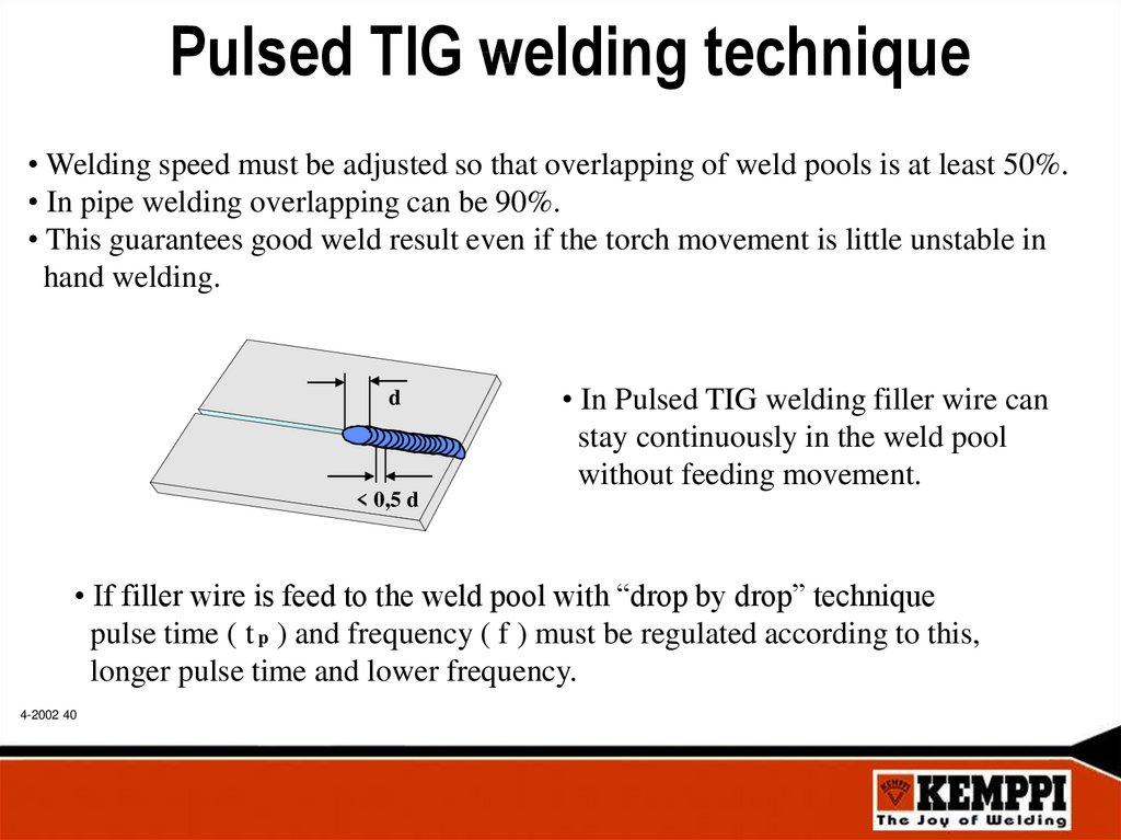
40.
Pulsed TIG welding technique• Welding speed must be adjusted so that overlapping of weld pools is at least 50%.
• In pipe welding overlapping can be 90%.
• This guarantees good weld result even if the torch movement is little unstable in
hand welding.
d
• In Pulsed TIG welding filler wire can
stay continuously in the weld pool
without feeding movement.
< 0,5 d
• If filler wire is feed to the weld pool with “drop by drop” technique
pulse time ( t p ) and frequency ( f ) must be regulated according to this,
longer pulse time and lower frequency.
4-2002 40
41.
Parameter setting on Pulsed TIG• In welding of steel use unsymmetrical pulse profile, pulse time t p = 30 - 40%.
• This gives long cooling time to avoid base material overheating.
• Use LP with slow pulse frequency, f = 0,5 - 1,0 Hz and continuous filler
wire feeding or “drop by drop” technique.
• Rapid pulsation RP ( f = > 50 Hz ) can also used with continuos filler wire feeding.
• Regulate Pulse current according to base material thickness so that penetration is
correct.
• Regulate background current low, so that cooling is effective.
• In outside corner joint welding is possible with or without filler wire.
4-2002 41
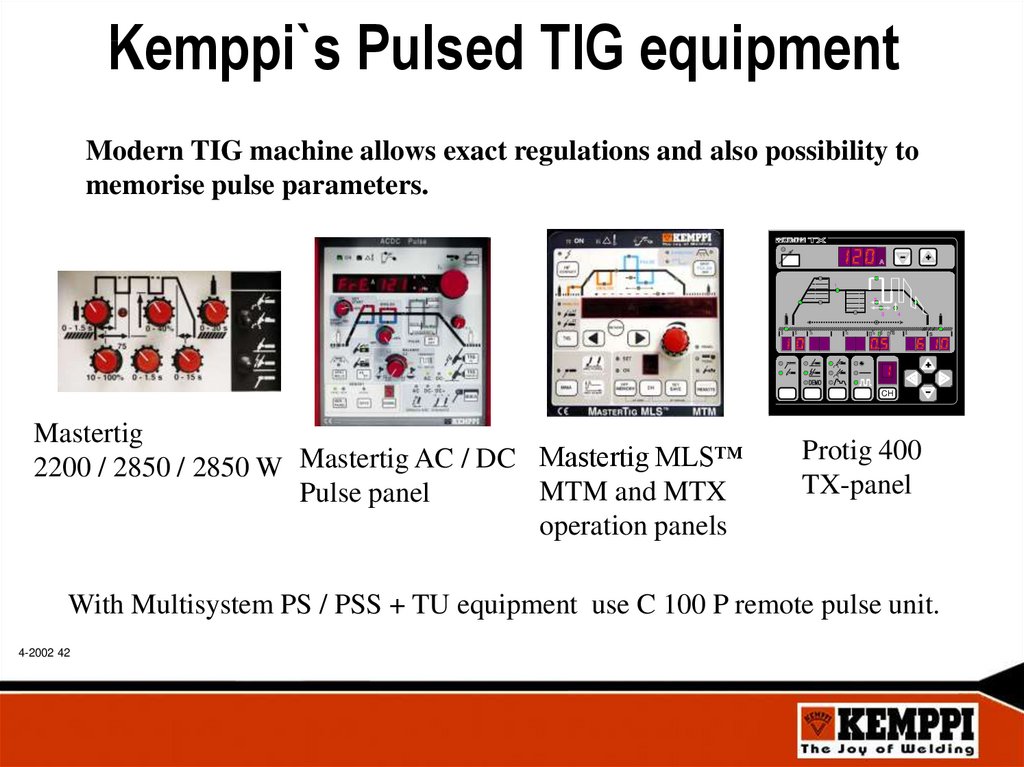
42.
Kemppi`s Pulsed TIG equipmentModern TIG machine allows exact regulations and also possibility to
memorise pulse parameters.
1
2
3
s
s
%
%
% s
4
ms
s
s
CH
Mastertig
2200 / 2850 / 2850 W Mastertig AC / DC Mastertig MLS™
MTM and MTX
Pulse panel
operation panels
Protig 400
TX-panel
With Multisystem PS / PSS + TU equipment use C 100 P remote pulse unit.
4-2002 42
43.
Pulsed DC TIG welding applicationsPulsed DC TIG welding is a flexible welding
process for all positions and plate thickness
• Out of position welding
• Pipe welding
• Visually important welds
• Welding without filler wire
• Welding of different plate thickness ( thick + thin )
• Special steel welding applications ( Steel + Ss )
• To avoid material overheating ( oxidization )
• To minimize deformation and control heat input
• Best results on outside corner joints and pipes
4-2002 43
44.
TIG Minilog functionWith Minilog function welder can select between two
pre-set current levels from the TIG torch trigger.
Current
time
Torch
trigger
4-2002 44
> 0.7 s
< 0.7 s
< 0.7 s > 0.7 s
45.
TIG Minilog benefitsTo avoid welding faults at starts
Better weld pool control in positional welding
Better weld pool control if air gap is varying
Welder can change position or take more filler
wire without breaking the arc
• For soft or hot - start
• Two value current “memory”
• Decreases need of remote control use
4-2002 45
46.
TIG Minilog applications• Pre heat of base material before welding
• Starting from thin material or from air cap
• Out of position welding
• Pipe welding
• When air gap is varying
• Welding of two different material thickness
• Welding of long seams
• Better control of penetration and heat input
• When two different current levels are needed
• Filler wire position change
4-2002 46
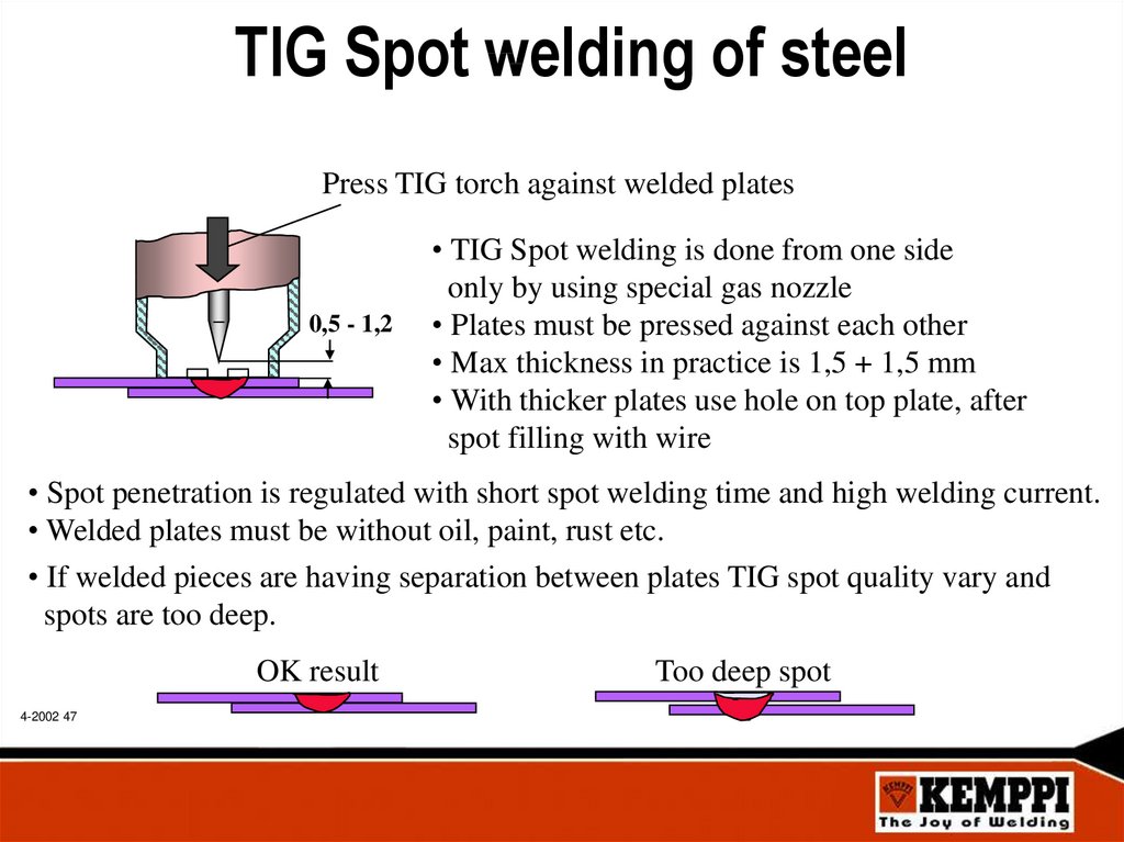
47.
TIG Spot welding of steelPress TIG torch against welded plates
0,5 - 1,2
• TIG Spot welding is done from one side
only by using special gas nozzle
• Plates must be pressed against each other
• Max thickness in practice is 1,5 + 1,5 mm
• With thicker plates use hole on top plate, after
spot filling with wire
• Spot penetration is regulated with short spot welding time and high welding current.
• Welded plates must be without oil, paint, rust etc.
• If welded pieces are having separation between plates TIG spot quality vary and
spots are too deep.
OK result
4-2002 47
Too deep spot
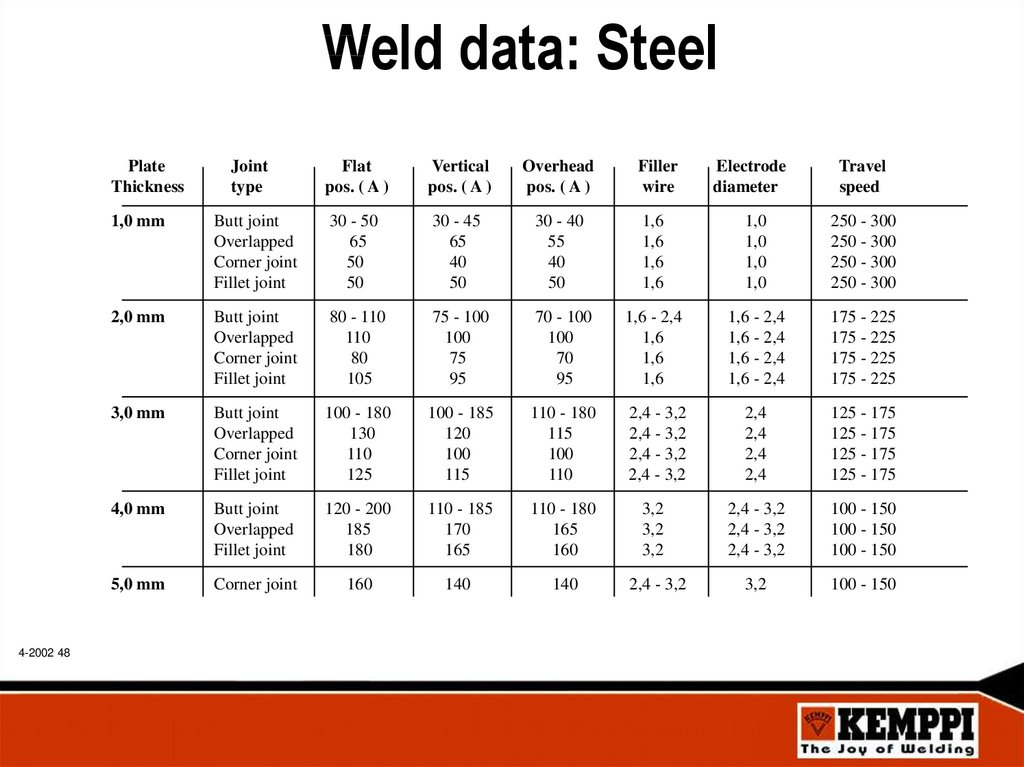
48.
Weld data: SteelPlate
Thickness
4-2002 48
Joint
type
Flat
pos. ( A )
Vertical
pos. ( A )
Overhead
pos. ( A )
Filler
wire
Electrode
diameter
Travel
speed
1,0 mm
Butt joint
Overlapped
Corner joint
Fillet joint
30 - 50
65
50
50
30 - 45
65
40
50
30 - 40
55
40
50
1,6
1,6
1,6
1,6
1,0
1,0
1,0
1,0
250 - 300
250 - 300
250 - 300
250 - 300
2,0 mm
Butt joint
Overlapped
Corner joint
Fillet joint
80 - 110
110
80
105
75 - 100
100
75
95
70 - 100
100
70
95
1,6 - 2,4
1,6
1,6
1,6
1,6 - 2,4
1,6 - 2,4
1,6 - 2,4
1,6 - 2,4
175 - 225
175 - 225
175 - 225
175 - 225
3,0 mm
Butt joint
Overlapped
Corner joint
Fillet joint
100 - 180
130
110
125
100 - 185
120
100
115
110 - 180
115
100
110
2,4 - 3,2
2,4 - 3,2
2,4 - 3,2
2,4 - 3,2
2,4
2,4
2,4
2,4
125 - 175
125 - 175
125 - 175
125 - 175
4,0 mm
Butt joint
Overlapped
Fillet joint
120 - 200
185
180
110 - 185
170
165
110 - 180
165
160
3,2
3,2
3,2
2,4 - 3,2
2,4 - 3,2
2,4 - 3,2
100 - 150
100 - 150
100 - 150
5,0 mm
Corner joint
160
140
140
2,4 - 3,2
3,2
100 - 150