 Lecturer - Oreshkov Vasiliy Ivanovich")


 internet
 informatics
Similar presentations:
. Lecture 2")


")

. Lec 1")


Hybrid fiber-coaxial network (HFC). Lecture 6
1. Name of discipline: Transmission systems of access networks (TSAN) Lecturer - Oreshkov Vasiliy Ivanovich
2.
Lecture 6HYBRID FIBER-COAXIAL
NETWORK
(HFC)
3.
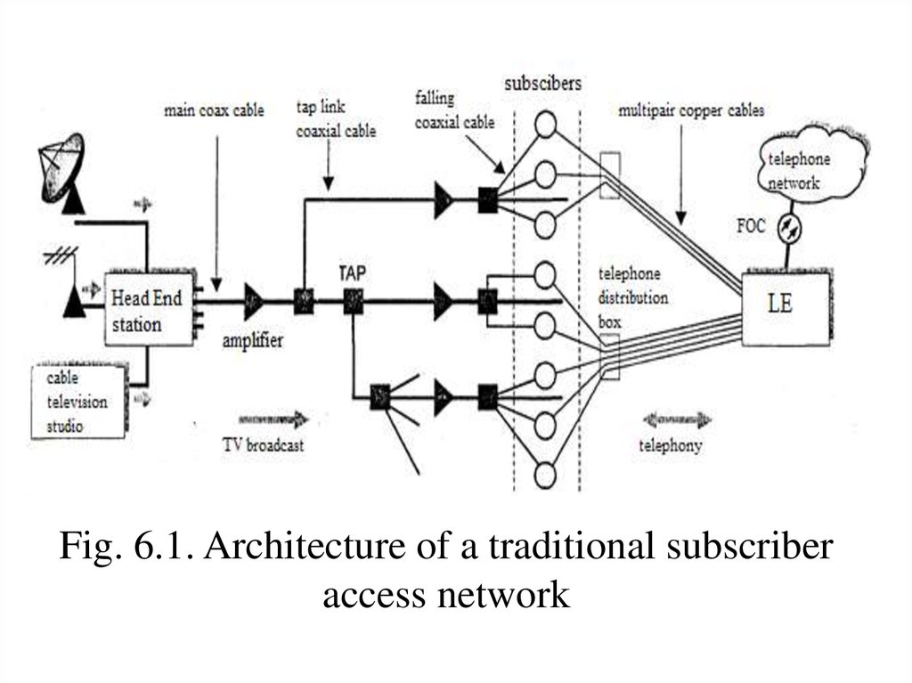
Traditional access by CATV andtelephone networks
Fig. 6.1 shows the general scheme of the
traditional subscriber network. Main
television
station (Head End station ) receives satellite and
terrestrial television channels as well as channels on
the local cable television studio, performing their
frequency multiplexing and forwards combined
broadband spectrum signal through the main coaxial
cable (trunk coax) - such stream of television
broadcasts from the head end to the subscribers is
called downstream.
4.
Fig. 6.1. Architecture of a traditional subscriberaccess network
5.
From the main cable to the branch nodes - taps(tap) - can be separated by one or several branches
of coaxial cable - coaxial branches (feeder coax) - in
this case the tap can contain built-in distribution
amplifier. Further branch cable tests, coming to the
subscriber tap , from which the subscribers directly
to the apartment followed by falling coaxial cables
(drop coax). Multi pair copper telephone cables are
run from the regional telephone exchanges to street
cabinets installed in residential areas , in each of
which there is a cross connection of twisted pair
cable from the exchange and cables from
subscribers.
6.
Thus, firstly, the network subscribers areprovided for receiving television channels.
Secondly, subscribers are provided with a
telephone service that is unlike television is
bidirectional. While traditional subscriber network
will be replaced by new networks such as HFC, they
still provide a very large installed base. The
maximum distance from the main node to the very
far end is 10 ... 15 km. The maximum number of
amplifiers in cascade is 35, the maximum number of
subscribers that can be connected to the trunk
coaxial cable, - 12500.
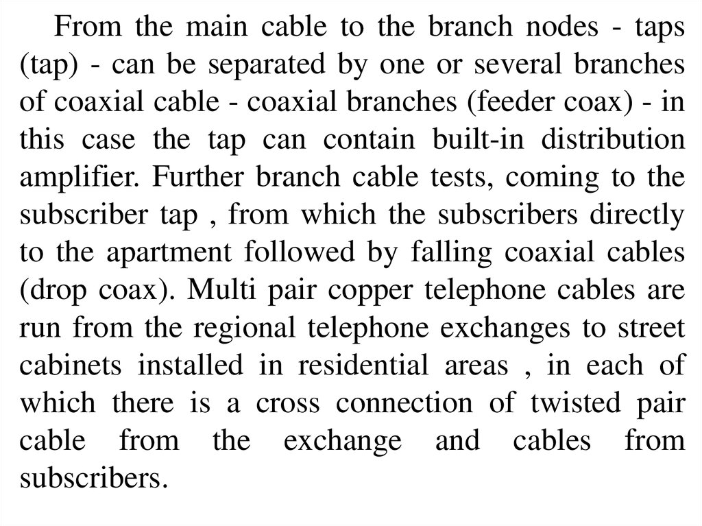
7.
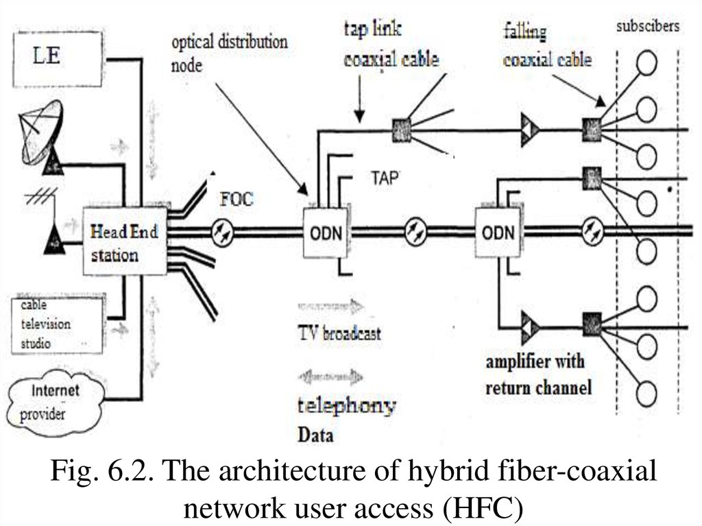
HFC networkThe hybrid fiber-coaxial network HFC (hybrid
fiber/coax) is based on the coaxial and fiber optic
cable systems , and uses the best features of each of
them (see Figure 6.2). HFC network is less
expensive compared to the network where the fiber
goes directly to every home (the concept of FTTH) only medium and large businesses can afford to
bring fiber directly to the office. At the same time the
HFC network provides a much more services than
traditional purely coaxial TV network. These
services include: video service, telephony,
interactive services , data services, etc.
8.
Fig. 6.2. The architecture of hybrid fiber-coaxialnetwork user access (HFC)
9.
Appointment of fiber in HFC networks much thesame as in telephone networks which, based on FOC
built more extended trunk lines between local and
city telephone exchange. In HFC networks the
maximum length of the FOC can be up to 80 km . In
a typical configuration, rack-mount optical laser
transmitters (mostly on the basis of DFB lasers ) in
the central office or head end transform broadband
radio frequency signals into equivalent analog
optical signals, which are followed by the FOC to
the corresponding optical distribution nodes (ODN).
10.
The optical signal coming in ODN, againconverted into an electrical\followed by coaxial
branches of the subscriber to the subscriber end
couplers maximum number of amplifiers in the
coaxial branches varies from 4 to 10 depending on
the architecture of the manufacturer. The maximum
number of users per one main POC from 500 to
3000.
The fundamental difference between these
networks from traditional subscriber coaxial cable
networks (along with the fact that the added fiberoptic tract) is a bi-directional traffic, that is, there is
flow from the subscriber to the main node, it is
upstream.
11.
Details of the HFC networkHFC network involves the installation of
equipment at a mutually agreed main node (HC,
main node controller, main controller ), at the
optical distribution node (ODN) and at the
subscriber side (ISU, integrated service unit, a
subscriber unit ). At present the development of a
standard IEEE 802.14, which determines the
methods of access to cable TV networks - MAC
level (especially with respect to network HFC), as
well as regulating the specification of the physical
layer, an alarm system and communication protocols
with local and global data networks.
12.
Many companies specializing in the production oftelecommunications network equipment supplying a
large inventory of HFC equipment. The most
advanced solutions provide companies: ADC
Telecommunications, Motorola, Nortel, NTT,
Scientific Atlanta, Warner Cable. First, they provide
a versatile transport solutions, tightly tied to the plan
worked out by the frequency of upward and
downward flows in accordance with the standards of
broadcast television networks. Second, is the
possibility to build the network, in particular the use
of the upper part of the spectrum band up to 1 GHz .
13.
The physical layer specifications ofthe 802.14 standard
802.14 physical layer specifications support
asymmetric bidirectional transmission of signals on
network HFC. HFC network allows for the
downstream connection type "point -to-multipoint"
topology with a generalized access branched tree ,
and for the upstream type compounds "multipoint to-point" - with the topology of the bus access .
The transfer controller is formed downstream of
the National Assembly and is broadcast, i.e.
mandatory to receive all subscriber devices.
14.
Upstream transmission devices formed on thesubscriber side of the ISU and reach the National
Assembly by the total coaxial distributed
environment.
One of the important problems which is solved in
the framework of the standard 802.14 - MAC
protocol is to support various types of traffic. Unlike
many other network standards, the HFC network to
support three main services:
- Constant bit rate (CBR);
- Variable bit rate (VBR);
- Available bit rate (ABR).
15.
These services have several different attributes, inparticular the allowable delay "explosive" nature of
traffic. Some applications are asymmetric in nature,
such as TV broadcasts. Other applications, on the
contrary, should strictly be symmetrical: voice, video
telephony. All of these requirements were taken into
account when creating the most optimal protocol.
16.
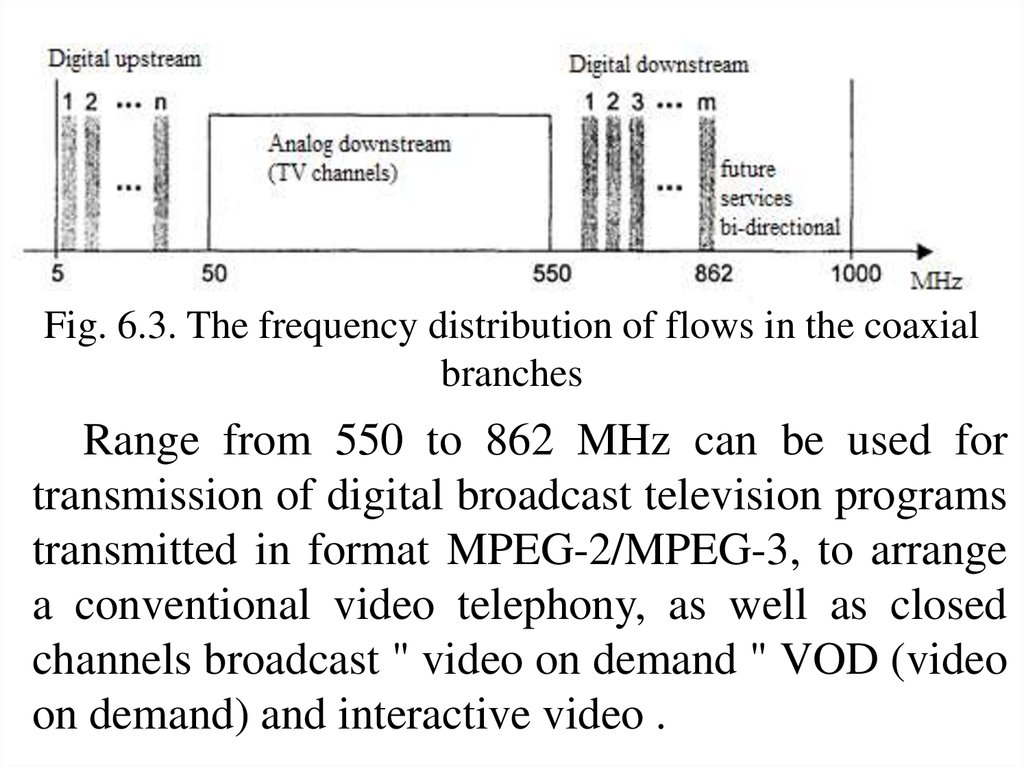
Frequency distribution of streamsGeneral diagram of the frequency distribution of
streams is shown in Fig. 6.3. As we can see, initially
supposed to use the frequency range from 5 to 862
MHz, and in the long term and the area from 862
MHz up to 1 GHz. Under the traditional analog TV
frequencies are removed from the 50 to 550 MHz. In
Ukraine adopted a television frequency grid with the
release of the band is 8 MHz on every TV channel.
17.
Fig. 6.3. The frequency distribution of flows in the coaxialbranches
Range from 550 to 862 MHz can be used for
transmission of digital broadcast television programs
transmitted in format MPEG-2/MPEG-3, to arrange
a conventional video telephony, as well as closed
channels broadcast " video on demand " VOD (video
on demand) and interactive video .
18.
The upstreams distributionThe carrier frequency fc must satisfy the condition:
Rs
Rs
f min 1
f c n 40 кГц f max 1
2
2
Where roll-off factor α = 0.25, n - integer, Rs symbol rate at the carrier frequency, and fmin and
fmax are determined from the table. 6.1.
Tab. 6.1. Upstream frequency plan
Region
North America
Europe
Japan
fmin, MHz
fmax, MHz
5
5
5
42
65
55
19.
In practice the choice of the frequency allocationof channels depends on factors (such as to avoid
overlaps in access, input and power loss) and not
regulated by standard 802.14.
The downstream distribution
A window that allowed placement of downstream
digital streams is different for the three regions
(Table 6.2). The large size of the window does not
mean that you can freely use any portion of the
spectrum. In that spectral range analog television
channels is placed.
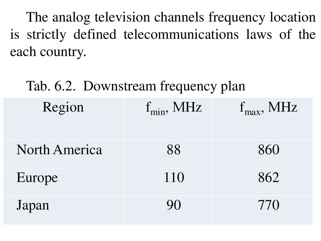
20.
The analog television channels frequency locationis strictly defined telecommunications laws of the
each country.
Tab. 6.2. Downstream frequency plan
Region
fmin, МHz
fmax, МHz
North America
88
860
Europe
110
862
Japan
90
770
21.
Physical features of upstream anddownstream
Using modulation schemes based on quadrature
amplitude modulation QAM-64 and QAM-256
allows to transmit downstream digital channels at the
rate of 30-40 Mbit/s , which is possible due to its low
noise levels. Reverse digital stream uses less prone
to interference modulation QAM- 16 and/or the
quadrature - phase modulation QPSK, since being
placed in the low-frequency part of the spectrum is
strongly influenced by noise. QPSK can send
streams of up to 2 ... 10 Mbit/s.
22.
Why does upstream locate in the lower part of thespectrum (5 ... 45 MHz )? First of all, this is due to
the asymmetry of downstream and upstream. To
increase the total (total in both directions) of
bandwidth, lower - largest stream should be placed
in the region of the spectrum with greater
redundancy code.
As a result, placing the lower part of the upstream
of the spectrum can be used in coaxial branches not
only bidirectional amplifiers and amplifier but with a
reverse channel, which amplify the signal forward
and reverse passes it unchanged.
23.
Since the attenuation in the coaxial cable lesssignificant in the low range, it allows the signal to
reach the receiver is connected to the ODN without
intermediate amplification while maintaining the
required power at reception.
Three types of physical layer PHY for downdrafts
A, B and C are supported by standard 802.14 (Table
6.3). Type C is identical to the type A for the major
exception that the type A uses an 8 MHz channel
(PAL / SECAM), and type C - 6 MHz (NTSC). The
main difference between types A and C methods
consists in coding.
24.
Tab. 6.3. Main parameters of the physical layer for thethree types down streams A, B, C
А
В
С
(Europe)
(North America) (Japan)
Nominal bandwidth, MHz
8
6
6
Coding method for
block RSTruncated coding block RSerror correcting
coding (RS- with external RS- coding
Reed-Solomon)
code
Modulation
QAM-64, QAM-256
Carrier frequency fc,
(n-250) ± 30
(n-250) ± 30
(n-250) ±
кГц
30
Roll-off factor,
0,15
0,18; 0,12
0,13
Parameters
Bitrate Rs, Мsymbols/s
6,0…6,95
5,057…5,064
5,19…5,36
5,0…5,31
25.
ConclusionsWe formulate the basic principles on which the
HFC network , and trends in their development :
- Broadband asymmetric streams: the stream from
the main node to the subscriber is much higher than
the reverse. Allowed a gradual migration to a more
symmetric traffic volume when upstream increases,
in particular the usage of high-frequency part of the
spectrum up to 1 GHz for bi-directional service.
- Hybrid system: fiber -optic cable and coaxial
cable plus twisted pair. Laid gradual transition to
FTTH infrastructure with the development of
technological and economic base.
26.
- Hybrid transmission of information: analog anddigital. Allowed a gradual transition to digital
transmission only.
- The distributed architecture of the network: the
network devices installed on the main node to the
distribution hub for the subscriber side. Perhaps the
gradual alignment of intelligence between network
elements .
- Integrated information flows cover almost all of
its types: voice, video, data in different formats.
IEEE 802.14 standard provides for a transition to a
universal transport of information technology-based
ATM, Ethernet.
27.
- Intelligent centralized network management,monitoring, testing, and distributed access to
management. It is allowed the redistribution of
information flows with the differentiation of
streams for the organization of services and
control flow elements of the network.
- Durability: "nested" structure of the redundant
cable network and basic equipment. Auto rebuild
in the event of an accident, distributed complex
power system.