


 informatics
Similar presentations:

")
")


Мікропроцесорна техніка. PSoC’s Routing Resources Цифрова частина системи
1.
Мікропроцесорнатехніка
(лекція 2)
Благітко Б.Я.
2018 р.
PSoC Designer 5.4
Designing with PSoC
2.
PSoC’s Routing ResourcesЦифрова частина системи
Digital PSoC Blocks
• Counter
• PWM
• Timer
2
3.
PWMs, Timers and CountersPWMs, Timers and Counters share many capabilities
but each provides specific capabilities.
• When to Use a PWM
The most common use of the PWM is to
generate periodic waveforms with adjustable duty
cycles. The PWM also provides optimized features for
power control, motor control, switching regulators and
lighting control. The PWM can also be used as a clock
divider by driving a clock into the clock input and using
the terminal count or a PWM output as the divided
clock output.
3
4.
PWMs, Timers and CountersWhen to Use a Counter
A Counter component is better used in
situations that require the counting of a number of
events but also provides rising edge capture input as
well as a compare output.
• When to Use a Timer
A Timer component is better used in
situations focused on timing the length of events,
measuring the interval of multiple rising and/or falling
edges, or for multiple capture events.
4
5.
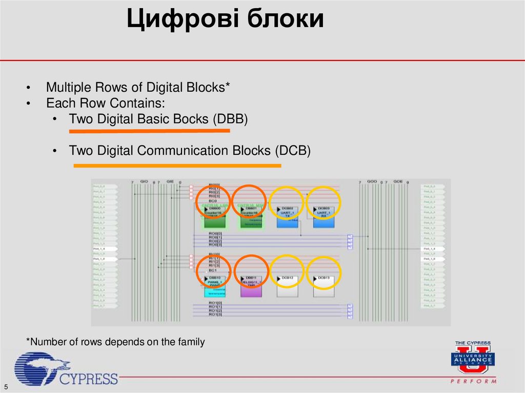
Цифрові блокиMultiple Rows of Digital Blocks*
Each Row Contains:
• Two Digital Basic Bocks (DBB)
• Two Digital Communication Blocks (DCB)
*Number of rows depends on the family
5
6.
Global Digital Interconnect16
Окремих
загальних
входів*
32 total nets for Digital Routing*
*Depends on the PSoC family
6
16
Окремих
загальних
виходів*
7.
Global Digital InterconnectОкремі загальні входи/ виходи
поділяються на парні та непарні
GIO =
Окремі
загальні
входи
(парні)
GIE =
Окремі
загальні
входи
(непарні)
7
GOO =
Окремі
загальні
виходи
(парні)
GOE =
Окремі
загальні
виходи
(непарні)
8.
Global Digital Interconnect• Global nets can be
used to:
• Під'єднання до інших
Global nets
• Під'єднання до Pins
Вхід:
8
Вихід:
9.
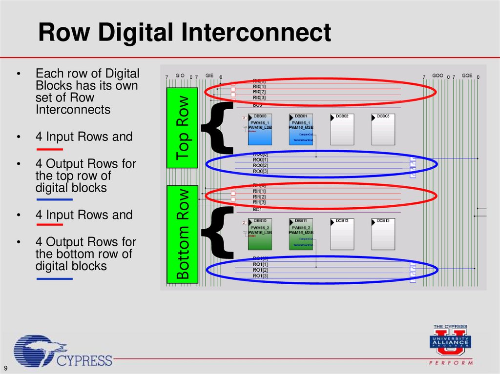
9Each row of Digital
Blocks has its own
set of Row
Interconnects
4 Input Rows and
4 Output Rows for
the top row of
digital blocks
4 Input Rows and
4 Output Rows for
the bottom row of
digital blocks
Bottom Row
Top Row
Row Digital Interconnect
10.
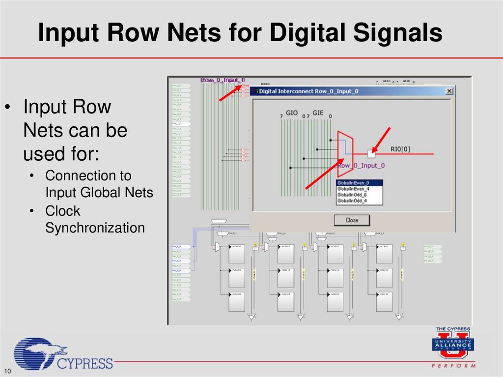
Input Row Nets for Digital Signals• Input Row
Nets can be
used for:
• Connection to
Input Global Nets
• Clock
Synchronization
10
11.
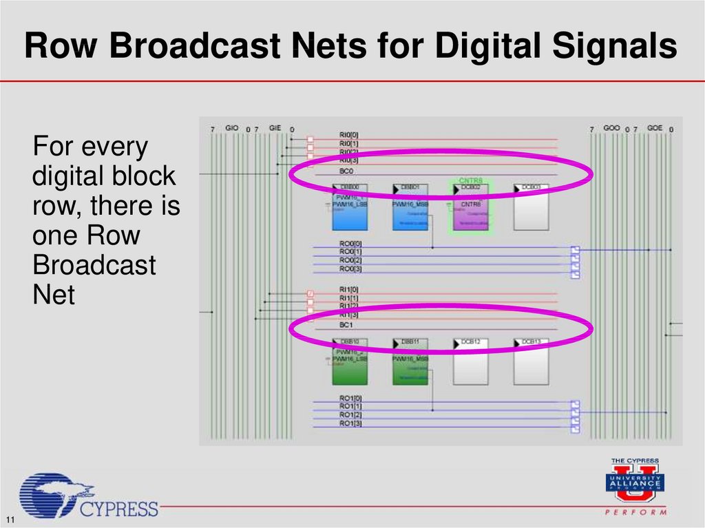
Row Broadcast Nets for Digital SignalsFor every
digital block
row, there is
one Row
Broadcast
Net
11
12.
Global Resources12
13.
Module ObjectivesAt the end of this module, you should be able to:
• List the three types of PSoC datasheets
• Give examples of when to use each type of
datasheet
• Describe the process of routing user modules out
to pins
• Outline the various design considerations of using
PSoC
13
14.
User Module DatasheetsEach user module has its own datasheet
contained within the PSoC Designer
software
14
User module block diagrams
Detailed user module specifications
Placement considerations
Example code
15.
PSoC Project Configuration Datasheet• User-defined pin outs
are color-coded and
detailed in the project
configuration
datasheet.
15
16.
PSoC Project Configuration Datasheet16
Project configuration
datasheets also
contain the
placement and
routing of user
modules
Project configuration
datasheets are
printable with the
click of a button
17.
Секція 1:Counters
18.
1819.
Properties Counter19
20.
Row Broadcast Nets for Digital Signals• Row Broadcast
Nets can be
connected to
• Each other
• A digital
block
• Thus, any digital
block can drive
any other digital
block or blocks
20
21.
Секція 2:PWM
22.
2223.
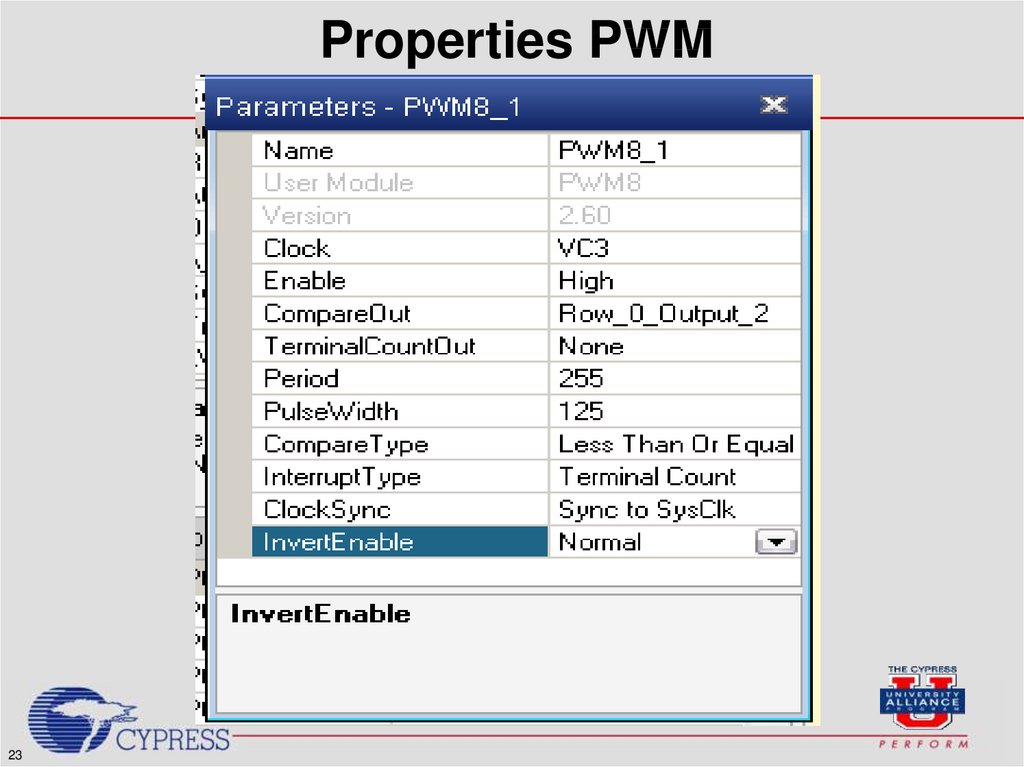
Properties PWM23
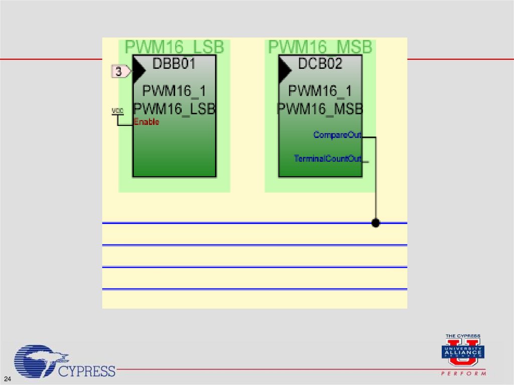
24.
2425.
Properties PWM25
26.
Секція 3:TIMER
27.
2728.
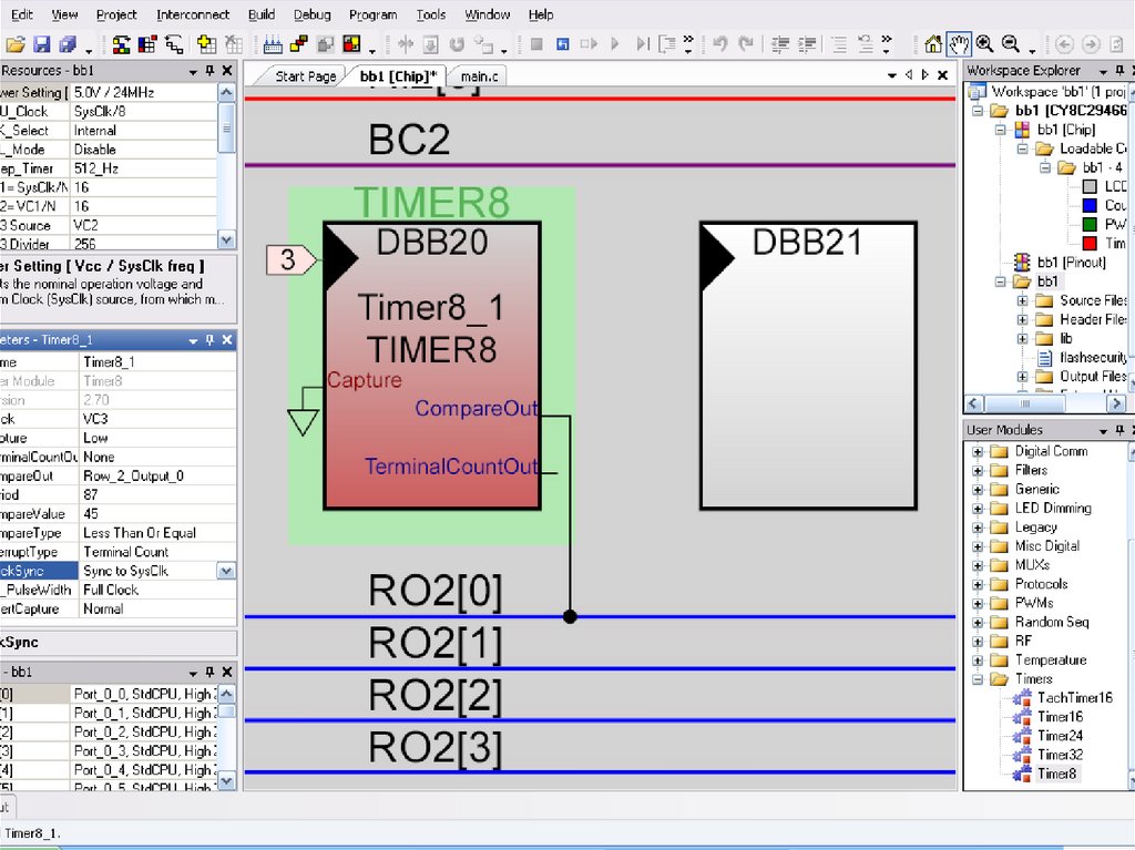
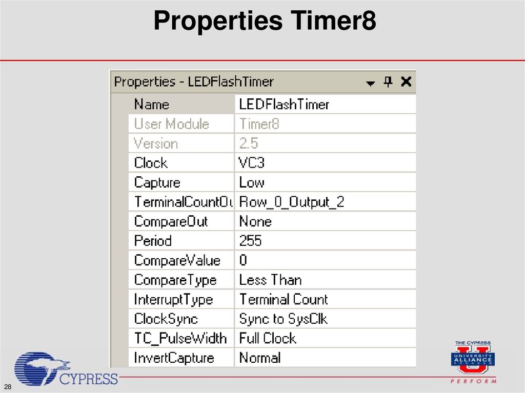
Properties Timer828
29.
The 8-bit timer is used to flash the LEDperiodically. It uses the interrupt generated
by
the
timer
to
toggle
the
LED.
• 1.
Place a Timer8 user module and rename it
LEDFlashTimer.
• 2.
Set the Clock to VC3.
• 3.
Set Capture to Low.
• 4.
Set TerminalCountOut to Row_0_Output_2.
• You’ll route the Terminal Count output to a pin so you
can get some practice routing resources in PSoC
Designer. You will connect the pin to an LED and set
the Drive mode on the pin so that it will flash the LED
for a single clock cycle every time the timer reaches
terminal count.
• 5.
Set CompareOut to None.
• 6.
Set the Period to 250.
29
30.
The 8-bit timer is used to flash the LEDperiodically. It uses the interrupt generated
by
the
timer
to
toggle
the
LED.
• 7.
Set the CompareValue to 0.
• 8.
Set the CompareType to Less Than.
• 9.
Set the InterruptType to Terminal
Count.
• 10. Set ClockSync to Sync to SysClk.
30
31.
The 8-bit timer is used to flash the LEDperiodically. It uses the interrupt generated
by
the
timer
to
toggle
the
LED.
• The flash rate of the LED will be 1/4 second.
(24 Mhz ч 3 (VC1) ч 16 (VC2) ч 250 (VC3
Divider) ч 250 (Period)) The timer will hit
terminal count 8 times per second and each of
these terminal counts toggles the LED.
31
32.
Мікропроцесорнатехніка
(лекція 2, кінець)
Благітко Б.Я.
2018р.
PSoC Designer 5.4
Designing with PSoC