


 english
Similar presentations:


Development of the optical module’s prototype for ArgonCube
1. Sergey Sokolov, DLNP, JINR Development of the optical module’s prototype for ArgonCube
2. ArgonCube LAr TPC concept
3.
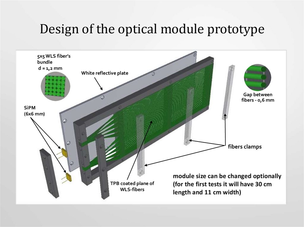
Design of the optical module prototype5x5 WLS fiber’s
bundle
d = 1,2 mm
White reflective plate
Gap between
fibers - 0,6 mm
SiPM
(6x6 mm)
fibers clamps
TPB coated plane of
WLS-fibers
module size can be changed optionally
(for the first tests it will have 30 cm
length and 11 cm width)
4.
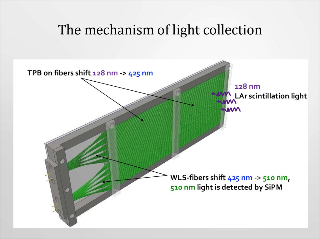
The mechanism of light collectionTPB on fibers shift 128 nm -> 425 nm
128 nm
LAr scintillation light
WLS-fibers shift 425 nm -> 510 nm,
510 nm light is detected by SiPM
5.
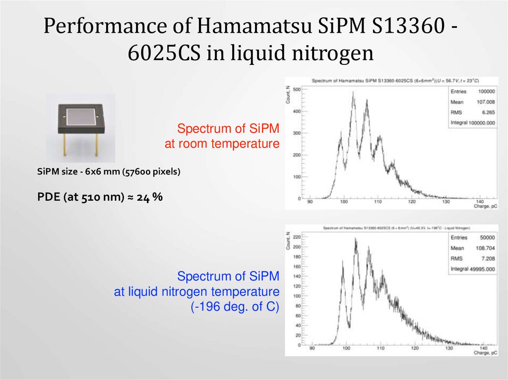
Performance of Hamamatsu SiPM S13360 6025CS in liquid nitrogenSpectrum of SiPM
at room temperature
SiPM size - 6x6 mm (57600 pixels)
PDE (at 510 nm) ≈ 24 %
Spectrum of SiPM
at liquid nitrogen temperature
(-196 deg. of C)
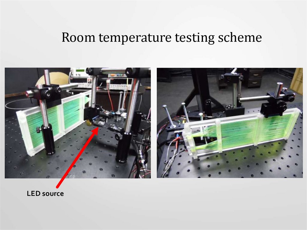
6. LED source
LED WL=428 nmLight diffusing by Teflon (PTFE) layer
7. LED stability
High light intensity ~ 103 ph.eAmplitude variations < 1%
LED source stability measured by
ECAL0 prototype for the COMPASS experiment
(Has precise photosensor temperature stabilization < 10 mdeg)
in june-july 2015 @ T10 (CERN).
Temperature variation in the hall: 24 (nignt) - 38 (day)
Low light intensity ≈ 1.75 ph.e
Amplitude variations < 2%
Fluctuations are mainly driven
by statistical accuracy
LED source stability measured by
20’’ Hamamatsu 12860 HQE PMT in a single point
8. LED calibration scheme
dark roomself-stabilized
LED (425 nm)
PMT H6780
QE ~ 18%
power
supply
signal
AMP
k=10
ADC
DRS4
power
supply
trigger
generator
trigger
controller
PC
PC
9.
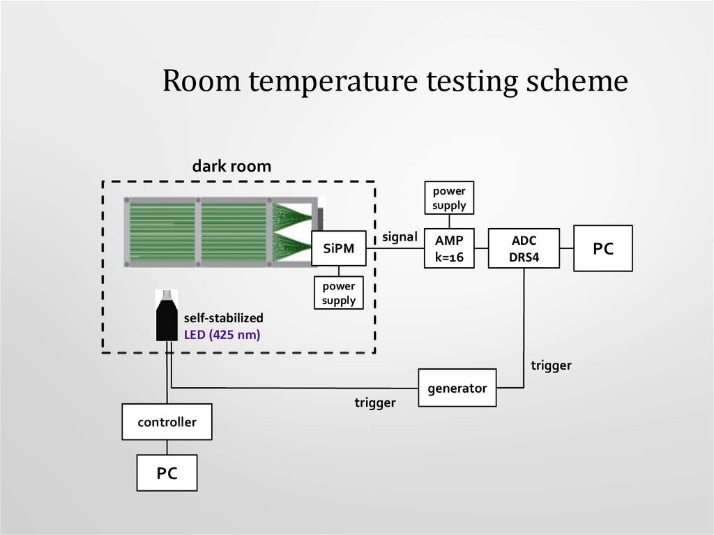
Room temperature testing schemedark room
power
supply
signal
SiPM
AMP
k=16
ADC
DRS4
power
supply
self-stabilized
LED (425 nm)
trigger
generator
trigger
controller
PC
PC
10.
Room temperature testing schemeLED source
11. Results of testing under room temperature conditions
U, V2 part
1 part
µ
PDE, %
µ
PDE, %
frame with
fibers
57
2,36
0,84
2,07
0,74
frame with
fibers +
white plate
57
3,14
1,12
2,85
1,02
frame with
fibers +
mirrored
faces
57
3,55
1,26
3,45
1,22
mirrored faces
frame with
fibers +
white plate
+ mirrored
faces
57
frame with
fibers +
mirrored
faces + TPB
57
4,94
1,76
4,84
1,72
self stabilized LED
N ~ 280 photons
1 part
3,50
1,25
3,18
1,13
2 part
12.
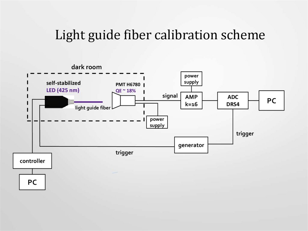
Light guide fiber calibration schemedark room
self-stabilized
LED (425 nm)
PMT H6780
QE ~ 18%
power
supply
signal
light guide fiber
AMP
k=16
ADC
DRS4
power
supply
trigger
generator
trigger
controller
PC
PC
13.
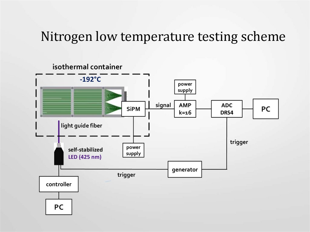
Nitrogen low temperature testing schemeisothermal container
-192°C
power
supply
SiPM
signal
AMP
k=16
ADC
DRS4
light guide fiber
self-stabilized
LED (425 nm)
trigger
controller
PC
trigger
power
supply
generator
PC
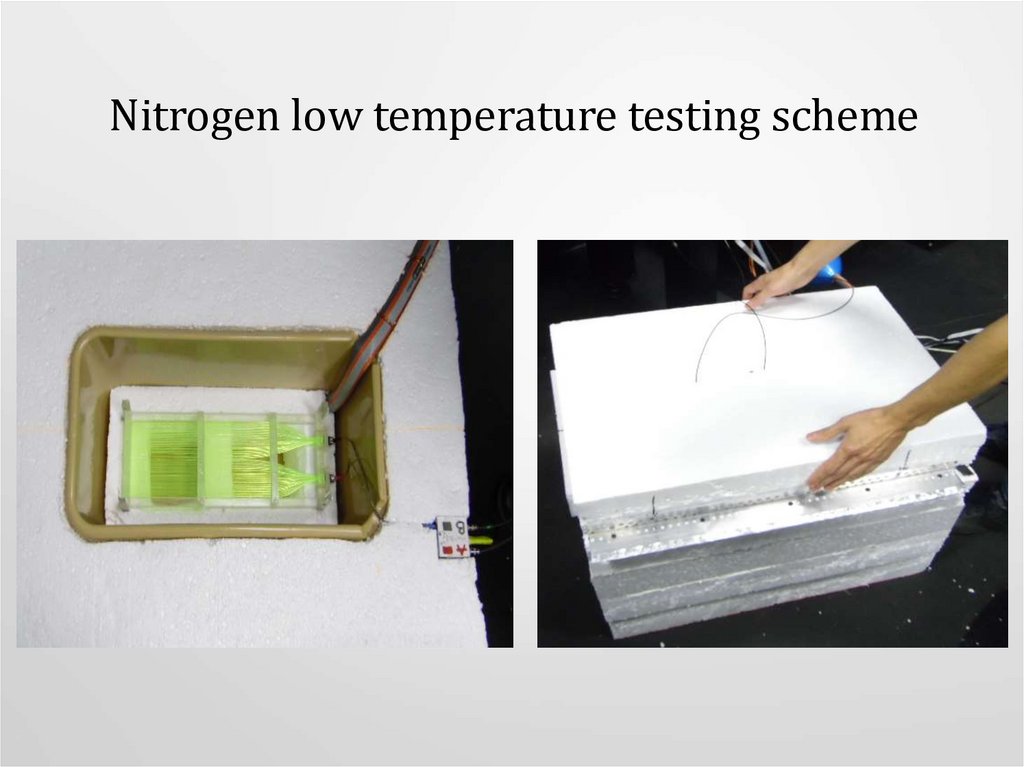
14.
Nitrogen low temperature testing scheme15. Results of testing under liquid nitrogen conditions
frame with fibers +mirrored faces
+TPB+LN
U, V
µ, ph.e.
PDE, %
46
5,57
1,99
46,5
5,9
2,09
47
6,16
2,19
47,5
6,38
2,26
48
6,58
2,34
16. The advanced prototype design
Maximum thickness ~ 10 mm (place to install SiPM )The rest thickness of module ~ 6 mm
The ends of the optical fibers will be round that will give us to
increase the light yield ~ 20 %
17. Assembling of prototypes
The next step will be to assemble the detector, what consist of 4 similar moduleThe size of the assembling will be 30*40 mm
18.
Conclusion• Optical module prototype reveals a good performance under
liquid nitrogen conditions
• Mirrored fiber faces and white plate usage lead to PDE increasing
• PDE in liquid nitrogen is higher then in the air, because of
different refractive indices
• TPB cover has no impact on prototype performance
• The tests of optical module prototype have shown a good light
collection performance
• The advanced prototype of the optical module is already under
construction