


")


")


 programming
Similar presentations:


 and the fundamental tree algorithm")


ENG 100 Introduction to Engineering. CAD-LAB-2: Surface Design – Rhino Automation – Solid Modeling (CSG & B-Rep)
1. ENG 100 Introduction to Engineering
CAD-LAB-2: Surface Design – Rhino Automation –Solid Modeling (CSG & B-Rep)
Fall semester, Academic Year 2018-19
Course Instructor:
Konstantinos Kostas (konstantinos.Kostas@nu.edu.kz)
2. Contents
1. CSG and B-Rep Solid Modeling2. Universal Joint
4. Circuit Diagram
3. Shaft Assembly
5. Wind turbine Blade
Nazarbayev University, ENG 100 - Introduction to Engineering
2
3. CSG
UNIONDIFFERENCE
CSG
Constructive solid
geometry (CSG) is an
approach followed in solid
modeling. Constructive solid
geometry allows a modeler to
create a complex surface or
object by
using Boolean operations to
combine simpler objects
(solid primitives)
and generate complex solid
models by such combinations.
Nazarbayev University, ENG 100 - Introduction to Engineering
INTERSECTION
3
4. B-rep
The second and most popular approach in solidmodeling and computer-aided design, is the boundary representation
(B-rep) approach for modeling solid objects. A solid is represented as a
collection of connected surface elements, the boundary between solid
and non-solid.
Boundary representation is more flexible and has a much richer
operation set than CSG. In addition to the Boolean operations, B-rep
has extrusion (or sweeping), chamfer, blending, drafting, shelling,
tweaking and many other operations as we will explore later.
Nazarbayev University, ENG 100 - Introduction to Engineering
4
5. Universal Joint (Universal coupling, U-Joint, Cardan Joint)
Nazarbayev University, ENG 100 - Introduction to Engineering5
6.
Nazarbayev University, ENG 100 - Introduction to Engineering6
7. 3d modeling of simple U-joint
• Description: Create the 3d model of the U-joint shown in previousslide.
• Assume all units are in mm.
• Put components shown in different colors in different layers.
• Create two copies of the model: one assembled and one
disassembled (as shown in previous slide).
• All components should be solid models.
• Assuming that all components will be made out of steel with a
relative density of 7.7, what will be the weight of the complete Ujoint when manufactured?
Nazarbayev University, ENG 100 - Introduction to Engineering
7
8. Modeling steps: Step 1
• Launch Rhino using mm as units and atolerance of 1 micron (=0.001mm)
• Create three layers, named “shaft”,
“sphere” and “joint” and use gray, blue
and red colors, respectively
• Make “shaft” layer the current layer and
create the shaft in the front viewport
• For example:
Create a cylinder with the appropriate
dimensions and generate the wedge slot by
Boolean difference. For the wedge slot you
may use an appropriately size box solid
Nazarbayev University, ENG 100 - Introduction to Engineering
8
9. Modeling steps: Step 2
• Create the second shaft by mirroring thefirst one (remember to set Copy to Yes in
mirror).
• Create the wedge by generating a box of
appropriate dimensions and the use
filletEdge to create the fillets (assume
that fillet arcs meet at the corresponding
side’s mid-point).
• Create the second wedge by copying the first one.
• Position the components similar to the positions in the image
shown above.
Nazarbayev University, ENG 100 - Introduction to Engineering
9
10. Modeling steps: Step 3
• Make “sphere” layer the current layer• Create a sphere with radius 9 and cut the
pieces that are not needed (you may use
Boolean differences with boxes or trim
the sphere with appropriately placed
lines and then cap the resulting surface
to get a solid
• Create one of sphere’s joint pins using two stacked cylinder and
• Generate the remaining pins by appropriately mirroring/rotating the
one you’ve create above
• Create a union of all sphere components to get a single solid
Nazarbayev University, ENG 100 - Introduction to Engineering
10
11. Modeling steps: Step 4
Sphere viewShaft view
• Make “joint” layer the current layer
• Create a cylinder with diameter 30 and
height 20 and use chamferEdge to create
the chamfering for both bases of the
cylinder.
• Use a cylinder (diameter 15) and
BooleanDifference to create the cavity in
the joint.
• Use a box and BooleanDifference to create the wedge’s slot in the
interior part of the cavity.
• Use a sphere with radius 9, positioned appropriately to create the
required cavity at the opposite face of the joint.
• The resulting joint should
a single solid object.
Nazarbayev University, ENG 100 - Introduction to Engineering
11
12. Modeling steps: Step 5
• On the sphere side of the joint, createthe two holding brackets:
• Create the first one by sketching its
border and a hole and then make it a
solid by extruding at a distance of 5mm
• Create the second bracket by mirroring
with respect to cylinder base’s center
• Use Boolean union to create a single joint and mirror the result to
get the second joint
• Rotate one set of shaft, wedge and joint by 90 degrees as shown in
the initial sketch
Nazarbayev University, ENG 100 - Introduction to Engineering
12
13. Modeling steps: Final Step
• The resulting modelshould like the first picture
besides
• Create a copy of all parts
and move the copied parts
to their final positions so
that you can get the
assembled model.
• Select all solids and type
volume to get the overall
volume. You should get a
value of around 47705.23
mm3. Hence, the overall
weight is approximately
367g
Nazarbayev University, ENG 100 - Introduction to Engineering
13
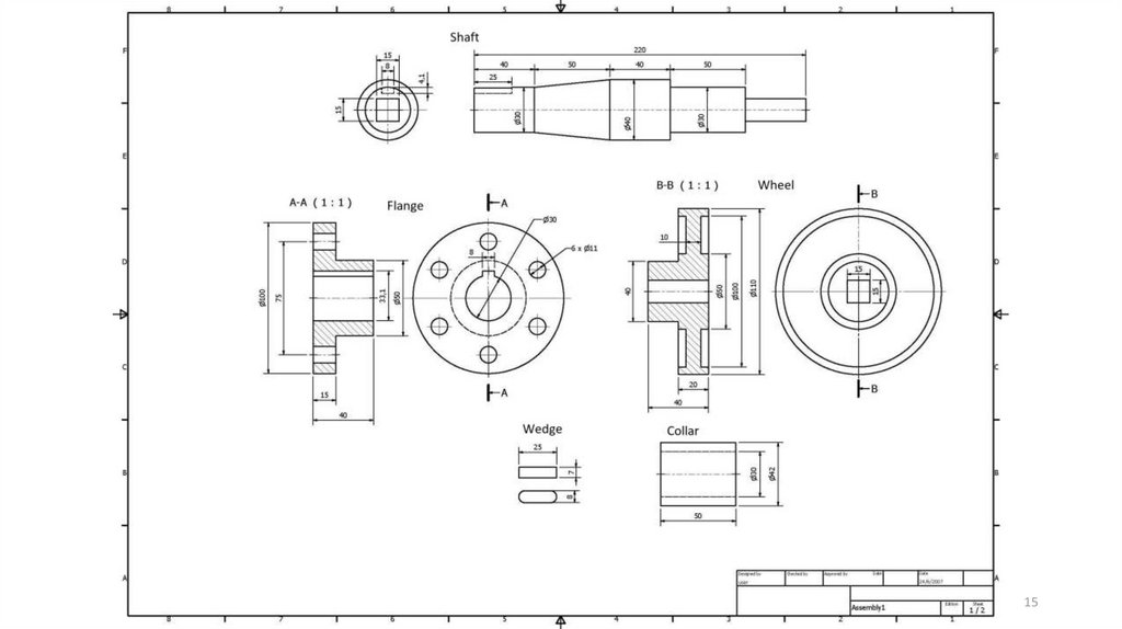
14. Shaft Assembly example
1.2.
3.
4.
5.
Shaft
Wedge
Flange
Wheel
Collar
• Assume all units are in
mm.
• Put components shown
in different colors in
different layers.
• All components should
be solid models.
Nazarbayev University, ENG 100 - Introduction to Engineering
14
15.
Nazarbayev University, ENG 100 - Introduction to Engineering15
16. Modeling Steps: Step 1
• Launch Rhino using mm as units and a tolerance of 1 micron(=0.001mm)
• Create five layers, named “shaft”, “flange”, “wheel”, “wedge” and
“collar”; pick a different color for each layer
• Make “shaft” layer the current layer and create the shaft in the front
viewport:
Create the profile of the circular cross-section part and generate the solid by
revolving the profile around the shaft’s axis (Use the Revolve command).
Create a box of an appropriate size and generate the wedge slot with the aid of
the BooleanDifference operation.
Create a box to represent the square cross-section part and finally use
BooleanUnion to generate one solid representing the shaft
Nazarbayev University, ENG 100 - Introduction to Engineering
16
17. Step 1 Result
Hints:1. Use the subcommand “from” when
moving/drawing a geometric entity with reference
to an existing point
2. The box used for cutting the wedge slot can have a
height larger than the slot’s height
3. There’s an option to create rectangles starting
from their center point
Nazarbayev University, ENG 100 - Introduction to Engineering
17
18. Modeling Steps: Step 2
• Make “flange” layer the current layer and create the flange in the ‘right’ or‘left’ viewport:
1. Create two circles with the same center and diameters 100 and 30, respectively.
2. Using the upper quad of the small circle as a base point, create a polyline to
represent the slot of the flange: the first point should be 3.1 mm above the quad;
use trim to remove the not-required part of the inner circle.
3. Create a circle of diameter 11 with a center that is 12.5 mm above the lower quad
of the outer circle; use arraypolar command to create the remaining circles around
the flange (use the common center of the two large circles as the center for the
command and generate 6 circles filling an angle of 360 degrees); see right sketch in
next slide.
4. Create the first part of the flange solid by extruding (ExtrudeCrv with solid option
set to Yes) all curves by 15 mm vertically to the construction plane.
Nazarbayev University, ENG 100 - Introduction to Engineering
18
19. Step 2 Result
5.Step 2 Result
6.
Create a circle with the same center as the outer circle
of the flange and a diameter equal to 50mm
Execute the ExtrudeCrv command (make sure the solid
option in set to yes), pick the newly created circle and
the inner circular section of solid lying on the same
plane as the selected circle and extrude both curves by
25mm; use union to unify the two extruded solids.
Nazarbayev University, ENG 100 - Introduction to Engineering
19
20. Modeling Steps: Step 3
• Make “wheel” layer the current layer and create the half of wheel’ssectional profile (ignore the square hole at the center; make sure the
profile is a single curve)
1. Use Revolve to create the wheel solid.
2. Create a rectangle (using the center-point
option) on one of the two bases (on the ‘left’ or
‘right’ view); use ExtrudeCrv to create the solid
representing the square-shaped hole at the
center of the wheel (Alternatively, a box with
appropriate dimensions could be used)
3. Use booleanDifference command to subtract
the box from the wheel solid.
Nazarbayev University, ENG 100 - Introduction to Engineering
20
21. Step 3 Result
Nazarbayev University, ENG 100 - Introduction to Engineering21
22. Modeling Steps: Step 4
Wedge: Make “wedge” layer thecurrent layer; create the wedge by
generating a box of appropriate
dimensions and the use filletEdge
to create the fillets (assume that
fillet arcs meet at the
corresponding side’s mid-point).
Collar: Make “collar” layer the current layer; create the collar by
drawing two same-centered circles with diameters 30 and 42 mm and
extruding both (ExtrudeCrv with solid option set to yes) straight for
50mm [use left or right view for the circles’ creation]
Nazarbayev University, ENG 100 - Introduction to Engineering
22
23. Modeling Steps: Final step (Assembly)
Nazarbayev University, ENG 100 - Introduction to Engineering23
24. A simple circuit diagram
Nazarbayev University, ENG 100 - Introduction to Engineering24
25. Modeling Steps: Step 1
• Create all components symbols as blocks using Rhino’s block commandlight-dependent resistor (LDR)
Potentiometer (variable resistor)
Resistor
LED
Transistor
9V Power source
• Create the wiring (use approximate dimensions) and add all components as
required
• Use Text command to add additional text on the diagram
• Use Insert command to insert already defined blocks and BlockManager to
manage block library
Nazarbayev University, ENG 100 - Introduction to Engineering
25
26. Step 1 Result
Nazarbayev University, ENG 100 - Introduction to Engineering26
27. Simplified Wind Turbine Blade
Nazarbayev University, ENG 100 - Introduction to Engineering27
28. Basic airfoil terminology
Nazarbayev University, ENG 100 - Introduction to Engineering28
29. Modeling Assumptions & input
Modeling Assumptions & inputAirfoil type A shape: points in file airfoilA.txt
Airfoil type B shape: points in file airfoilB.txt
Assume an overall blade length L = 45m
Twist rotation is performed with respect to airfoil’s center (assume center
to lie on the airfoil’s chord, 1/3 the distance from leading to trailing edge
• Remaining dimensions and measurements as shown below:
Nazarbayev University, ENG 100 - Introduction to Engineering
29
30. Modeling Steps: Step 1
• Modify airfoilA.txt and airfoilB.txt to include the appropriate Rhino command(InterpCrv) to facilitate the automatic generation of the corresponding curves
• Using Tools Command Read from File… construct the two airfoils
• Create the hub-connection section (circular section) and place it at L=0m
• Place a scaled copy (enlarged by a factor of 4) of airfoilA at L=5m and L=10m
• Place a scaled copy (enlarged by a factor of 2) of airfoilB at L=45m
• Place a scaled copy (compute the required factor) of airfoilB at L=20m
• Rotate Type A airfoil copies 20o around blade’s longitudinal axis (with respect to
airfoil’s center)
• Rotate the airfoil placed at L=20m using the required angle
• Create at least two intermediate sections between L=20m and L=45m
Nazarbayev University, ENG 100 - Introduction to Engineering
30
31. Step 1 Result
Nazarbayev University, ENG 100 - Introduction to Engineering31
32. Modeling Steps: Step 2
• Use ExtrudeCrv to model the part between L=5 and L=10 (solid optionshould be set to No)
• Use Sweep1 or Sweep2 or Loft to generate the part between L=10
and L=45. Make sure that you interpolate all sections in that part and
that you create the required rails, if you use Sweep1 or Sweep2. In all
cases, pick the edge of the first surface so that you can create a
tangent continuous surface.
• Use BlendSrf to create the surface patch between the hub and the
first airfoil section. You may create an auxiliary cylindrical surface next
to the circular section to get the required tangent plane information.
Nazarbayev University, ENG 100 - Introduction to Engineering
32
33. Step 2 Result
Using the Zebracommand you may
check the tangential
continuity between
surface patches
Nazarbayev University, ENG 100 - Introduction to Engineering
33
34. Modeling Steps: Step 3
• Join all surfaces together using the join command• Use the cap command to create the missing planar surfaces and
complete the blade solid model.
• Use the volume command to get the volume of the blade. If Rhino
reports no volume then you probably have some gap(s) in your
model:
• Use ShowEdges and look for any Naked or Non-manifold edges. If such edges
exist you need to remodel the parts affected.
• If the gap is small, using JoinEdge might fix the problem for naked edges.
Nazarbayev University, ENG 100 - Introduction to Engineering
34
35. Modeling Steps: Final step
The overall volumeof the wind turbine
blade should be
around 43.78 m3
Nazarbayev University, ENG 100 - Introduction to Engineering
35