


 programming
Similar presentations:


")
")


Easy access to embedded at SIM800(R)
1.
EASY ACCESS to EMBEDDED ATSIM800(R)
2.
Content1. Embedded AT Core Conception
2. Embedded AT Functions
3. Example: ADC Detection
2
3.
1. Embedded AT Core Conception1.1 Embedded AT Core Conception
1.2 Think from MCU Side
1.3 Programming Style
Back
3
4.
1.1 Embedded AT Core ConceptionPurpose:
Embedded AT will fully utilize SIM800/H resources, provide interfaces to
move external MCU functions inside SIM800/H, so as to save customer’s
cost.
Programming Idea:
Think from MCU side
Similar MCU programming style
Back
4
5.
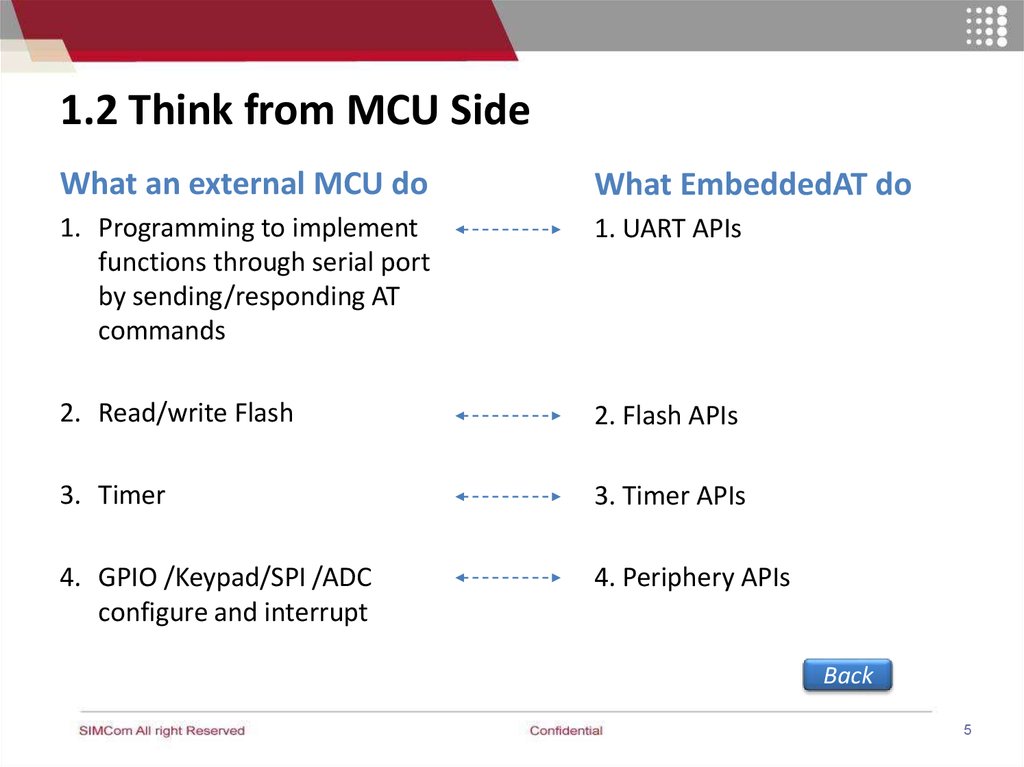
1.2 Think from MCU SideWhat an external MCU do
What EmbeddedAT do
1. Programming to implement
functions through serial port
by sending/responding AT
commands
1. UART APIs
2. Read/write Flash
2. Flash APIs
3. Timer
3. Timer APIs
4. GPIO /Keypad/SPI /ADC
configure and interrupt
4. Periphery APIs
Back
5
6.
1.3 Programming StyleMCU Framework
EMBEDDED-AT Framework
void main(void)
{
Init Hardware();
Init Variable();
Start Timer();
while(TRUE)
{
void app_main (void)
{ Init RAM and clib();
Init Hardware();
Init Variable();
eat_timer_start(EAT_TIMER_1, 1000);
while(TRUE)
{
eat_get_event(&event);
switch(event.event)
{
case EAT_EVENT_MDM_READY_RD :
{…}
case EAT_EVENT_TIMER : {…}
Back
…
}}}
Progress ModemData();
Progress Timer();
….
}}
6
7.
2. Embedded AT Functions2.1 Send and Receive AT Command
2.2 FLASH Operation
2.3 Timer
2.4 GPIO Configuration and Usage
2.5 SPI Interface
2.6 UART Operation
Back
7
8.
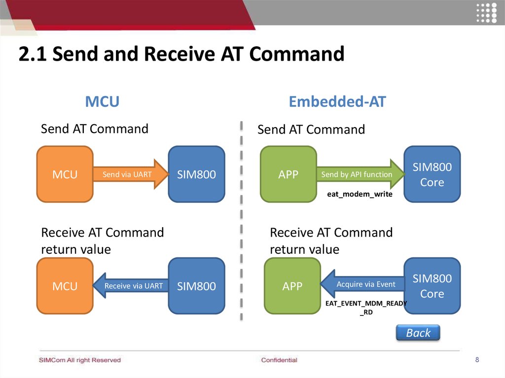
2.1 Send and Receive AT CommandMCU
Embedded-AT
Send AT Command
MCU
Send via UART
Send AT Command
SIM800
APP
SIM800
Core
Send by API function
eat_modem_write
Receive AT Command
return value
MCU
Receive via UART
Receive AT Command
return value
SIM800
APP
Acquire via Event
EAT_EVENT_MDM_READY
_RD
SIM800
Core
Back
8
9.
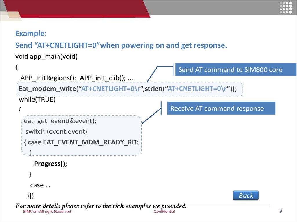
Example:Send “AT+CNETLIGHT=0”when powering on and get response.
void app_main(void)
{
Send AT command to SIM800 core
APP_InitRegions(); APP_init_clib(); …
Eat_modem_write(“AT+CNETLIGHT=0\r”,strlen(“AT+CNETLIGHT=0\r”));
while(TRUE)
Receive AT command response
{
eat_get_event(&event);
switch (event.event)
{ case EAT_EVENT_MDM_READY_RD:
{
Progress();
}
case …
Back
}}}
For more details please refer to the rich examples we provided.
9
10.
2.2 FLASH Operation2.2.1 Read data
2.2.2 Write Data
2.2.3 Other Flash APIs
Back
10
11.
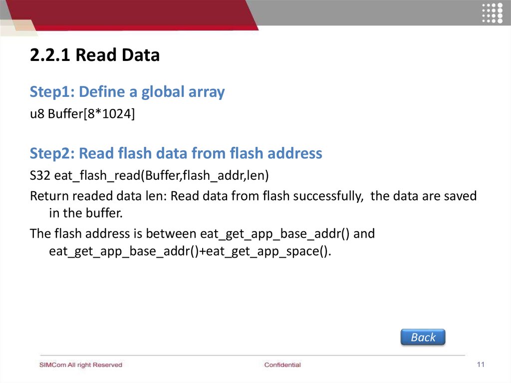
2.2.1 Read DataStep1: Define a global array
u8 Buffer[8*1024]
Step2: Read flash data from flash address
S32 eat_flash_read(Buffer,flash_addr,len)
Return readed data len: Read data from flash successfully, the data are saved
in the buffer.
The flash address is between eat_get_app_base_addr() and
eat_get_app_base_addr()+eat_get_app_space().
Back
11
12.
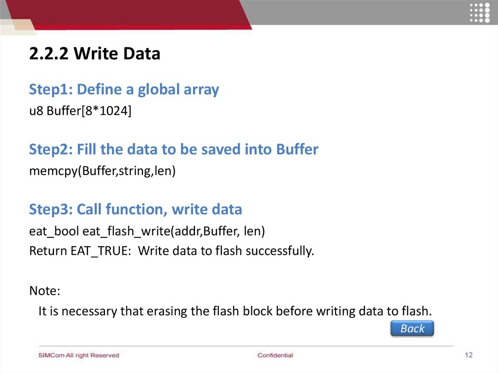
2.2.2 Write DataStep1: Define a global array
u8 Buffer[8*1024]
Step2: Fill the data to be saved into Buffer
memcpy(Buffer,string,len)
Step3: Call function, write data
eat_bool eat_flash_write(addr,Buffer, len)
Return EAT_TRUE: Write data to flash successfully.
Note:
It is necessary that erasing the flash block before writing data to flash.
Back
12
13.
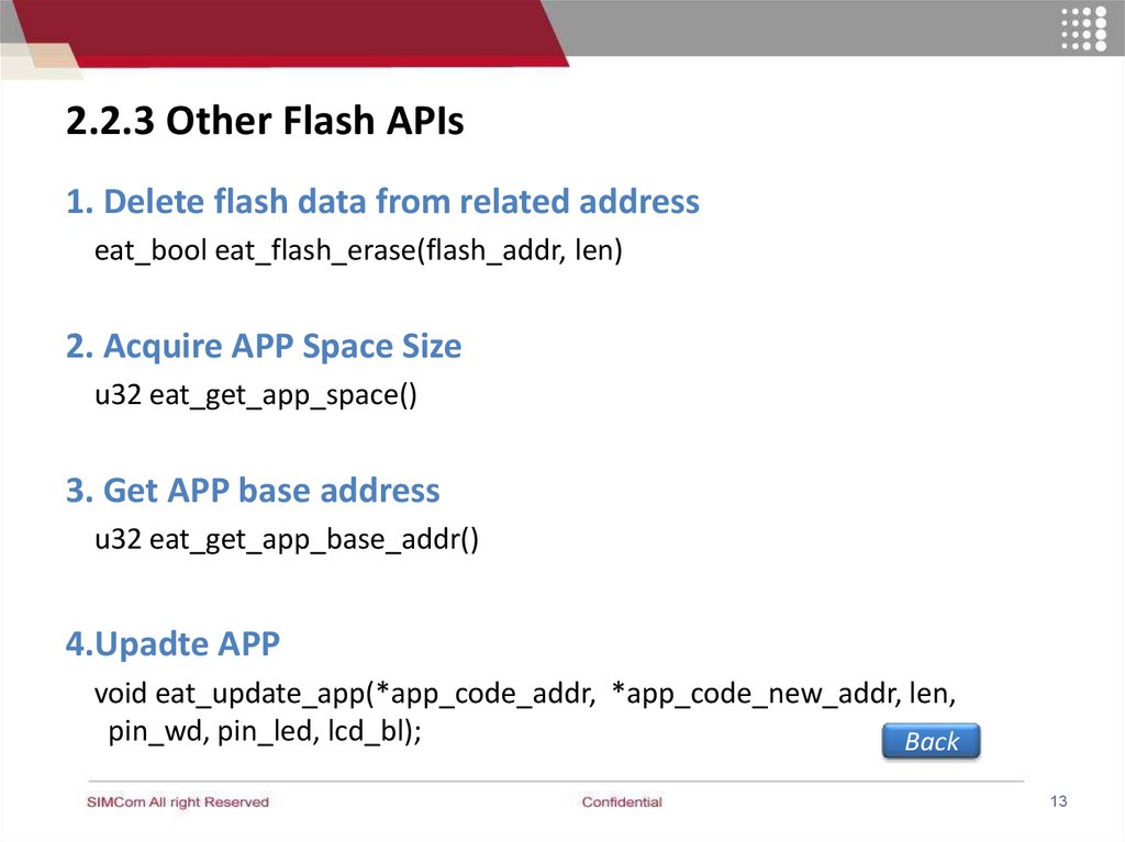
2.2.3 Other Flash APIs1. Delete flash data from related address
eat_bool eat_flash_erase(flash_addr, len)
2. Acquire APP Space Size
u32 eat_get_app_space()
3. Get APP base address
u32 eat_get_app_base_addr()
4.Upadte APP
void eat_update_app(*app_code_addr, *app_code_new_addr, len,
pin_wd, pin_led, lcd_bl);
Back
13
14.
2.3 Timer2.3.1 Start / Stop Timer
2.3.2 Timer EVENT
2.3.3 Get System time
Back
14
15.
2.3.2 Start / Stop TimerStart or stop timer
Soft timer:
Start timer: eat_timer_start(timer_id, expire_ms);
Stop timer: eat_timer_stop(timer_id)
Return EAT_TRUE: Start /stop a timer successfully.
Hardware timer:
eat_gpt_start(expire_61us,loop, gpt_expire_cb_fun);
Back
15
16.
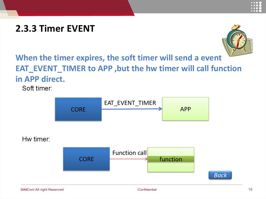
2.3.3 Timer EVENTWhen the timer expires, the soft timer will send a event
EAT_EVENT_TIMER to APP ,but the hw timer will call function
in APP direct.
Soft timer:
CORE
EAT_EVENT_TIMER
APP
Hw timer:
CORE
Function call
function
APP
Back
16
17.
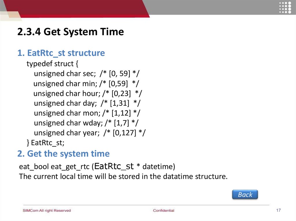
2.3.4 Get System Time1. EatRtc_st structure
typedef struct {
unsigned char sec; /* [0, 59] */
unsigned char min; /* [0,59] */
unsigned char hour; /* [0,23] */
unsigned char day; /* [1,31] */
unsigned char mon; /* [1,12] */
unsigned char wday; /* [1,7] */
unsigned char year; /* [0,127] */
} EatRtc_st;
2. Get the system time
eat_bool eat_get_rtc (EatRtc_st * datetime)
The current local time will be stored in the datatime structure.
Back
17
18.
2.4 Configuration and Usage of GPIO2.4.1 Pins for GPIO
2.4.2 Configure PIN to GPO
2.4.3 Configure PIN to GPI
2.4.4 Configure PIN to be Interruptable
2.4.5 Configure PIN for Keypad
Back
18
19.
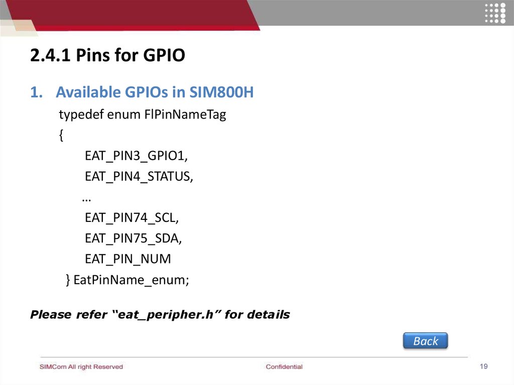
2.4.1 Pins for GPIO1. Available GPIOs in SIM800H
typedef enum FlPinNameTag
{
EAT_PIN3_GPIO1,
EAT_PIN4_STATUS,
…
EAT_PIN74_SCL,
EAT_PIN75_SDA,
EAT_PIN_NUM
} EatPinName_enum;
Please refer “eat_peripher.h” for details
Back
19
20.
2.4.2 Configure PIN to GPIO and output modeStep1: Configure the target PIN as GPIO
eat_bool eat_pin_set_mode(PIN, EAT_PIN_MODE_GPIO);
Return EAT_TRUE : Configure status successful
Step2: Configure the target GPIO to be out and high level or
low
eat_bool eat_gpio_setup(PIN, EAT_GPIO_DIR_OUTPUT ,
EAT_GPIO_LEVEL_HIGH)
Return EAT_TRUE : Configuration successful
Back
20
21.
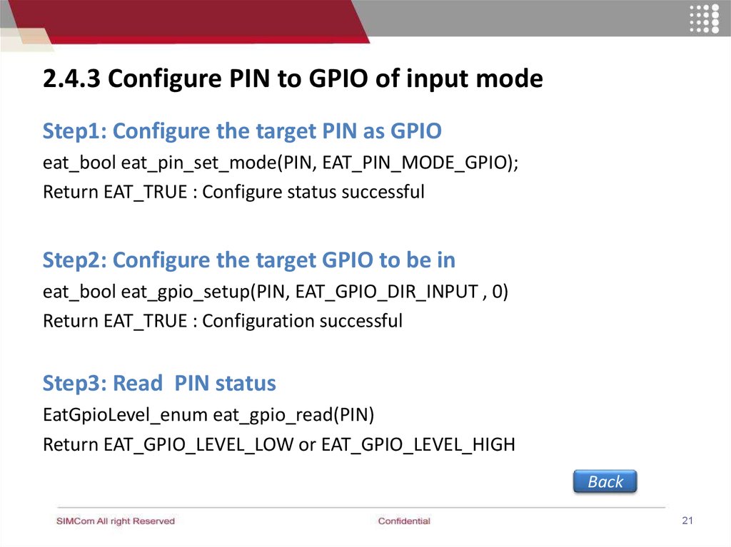
2.4.3 Configure PIN to GPIO of input modeStep1: Configure the target PIN as GPIO
eat_bool eat_pin_set_mode(PIN, EAT_PIN_MODE_GPIO);
Return EAT_TRUE : Configure status successful
Step2: Configure the target GPIO to be in
eat_bool eat_gpio_setup(PIN, EAT_GPIO_DIR_INPUT , 0)
Return EAT_TRUE : Configuration successful
Step3: Read PIN status
EatGpioLevel_enum eat_gpio_read(PIN)
Return EAT_GPIO_LEVEL_LOW or EAT_GPIO_LEVEL_HIGH
Back
21
22.
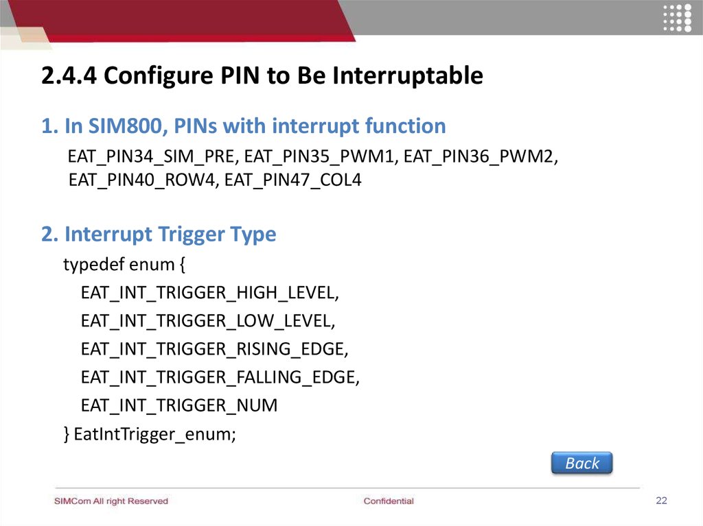
2.4.4 Configure PIN to Be Interruptable1. In SIM800, PINs with interrupt function
EAT_PIN34_SIM_PRE, EAT_PIN35_PWM1, EAT_PIN36_PWM2,
EAT_PIN40_ROW4, EAT_PIN47_COL4
2. Interrupt Trigger Type
typedef enum {
EAT_INT_TRIGGER_HIGH_LEVEL,
EAT_INT_TRIGGER_LOW_LEVEL,
EAT_INT_TRIGGER_RISING_EDGE,
EAT_INT_TRIGGER_FALLING_EDGE,
EAT_INT_TRIGGER_NUM
} EatIntTrigger_enum;
Back
22
23.
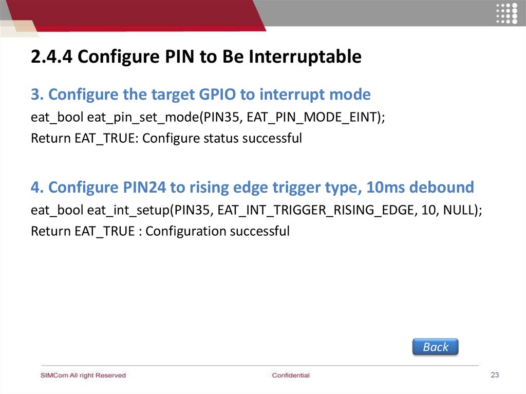
2.4.4 Configure PIN to Be Interruptable3. Configure the target GPIO to interrupt mode
eat_bool eat_pin_set_mode(PIN35, EAT_PIN_MODE_EINT);
Return EAT_TRUE: Configure status successful
4. Configure PIN24 to rising edge trigger type, 10ms debound
eat_bool eat_int_setup(PIN35, EAT_INT_TRIGGER_RISING_EDGE, 10, NULL);
Return EAT_TRUE : Configuration successful
Back
23
24.
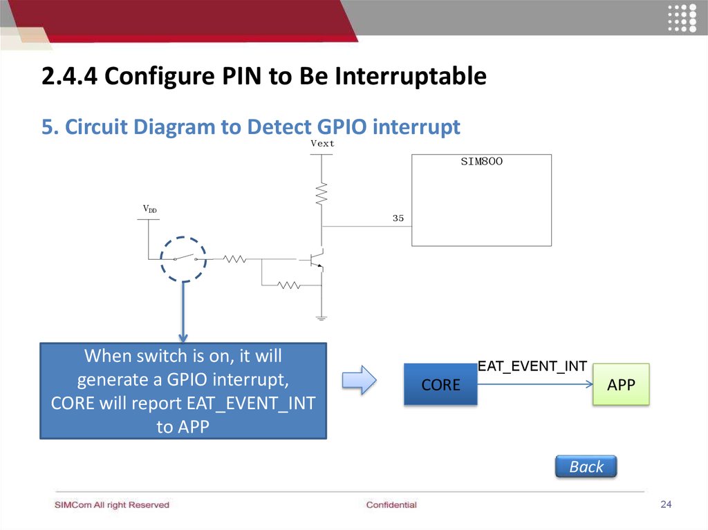
2.4.4 Configure PIN to Be Interruptable5. Circuit Diagram to Detect GPIO interrupt
Vext
SIM800
VDD
When switch is on, it will
generate a GPIO interrupt,
CORE will report EAT_EVENT_INT
to APP
35
EAT_EVENT_INT
CORE
APP
Back
24
25.
2.4.5 Configure PIN for Keypad1. Initializes keypad pins
eat_bool eat_pin_set_mode(pin, EAT_PIN_MODE_KEY);
Note:
If any of the KEYPAD pin is configured as keypad, all KEYPAD pins
are KEYPAD;
If any of the KEYPAD pin is configured as GPIO, then all KEYPAD
pins are GPIO.
25
26.
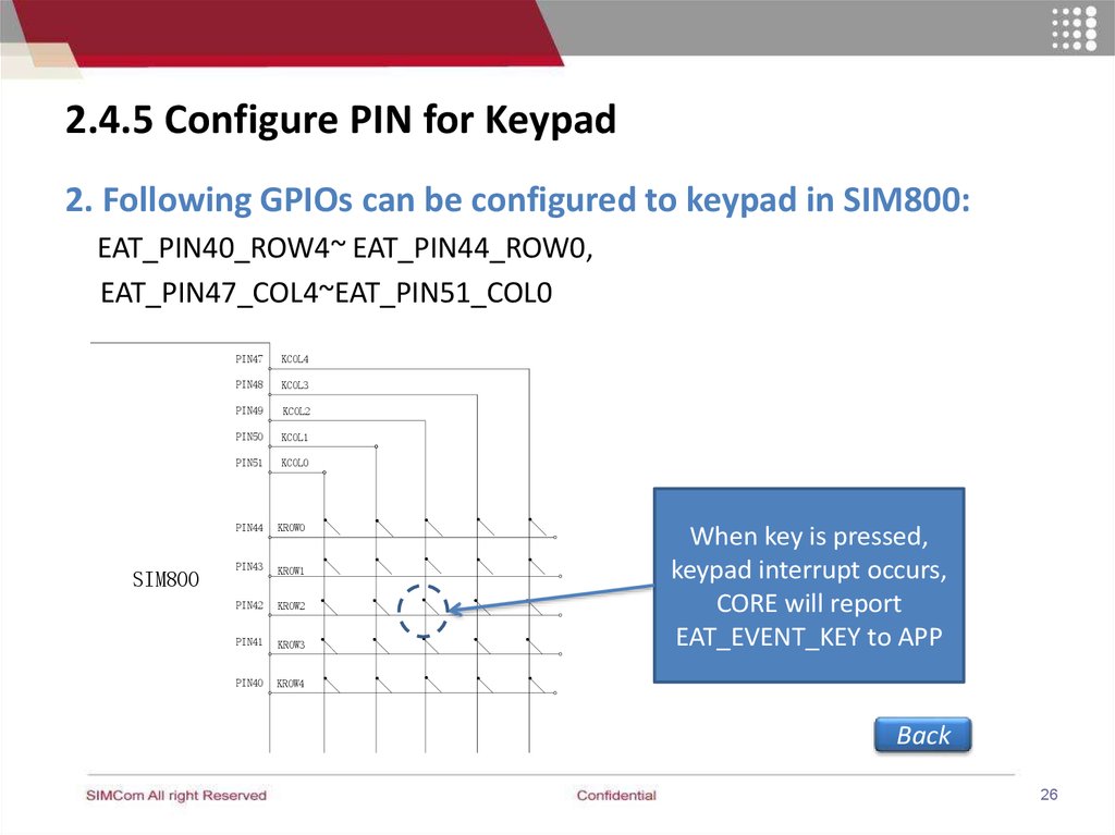
2.4.5 Configure PIN for Keypad2. Following GPIOs can be configured to keypad in SIM800:
EAT_PIN40_ROW4~ EAT_PIN44_ROW0,
EAT_PIN47_COL4~EAT_PIN51_COL0
SIM800
PIN47
KCOL4
PIN48
KCOL3
PIN49
KCOL2
PIN50
KCOL1
PIN51
KCOL0
PIN44
KROW0
PIN43
KROW1
PIN42
KROW2
PIN41
KROW3
PIN40
KROW4
When key is pressed,
keypad interrupt occurs,
CORE will report
EAT_EVENT_KEY to APP
Back
26
27.
2.4.5 Configure PIN for Keypad3. EAT_EVENT_KEY report to APP
CORE
EAT_EVENT_KEY
key_val
APP
4. The values of each key(key_val) are as following:
typedef enum {
EAT_KEY_C0R0,
……
EAT_KEY_C4R4,
EAT_KEY_NUM
} EatKey_enum;
Back
27
28.
2.5 SPI Interface1.Configure SPI bus, set according to actual situation
eat_bool eat_spi_init(clk, wire, bit, enable_SDI, enable_cs);
2. Write data to SPI bus
eat_bool eat_spi_write(*data, len, is_command);
3. Read single byte from SPI bus
u8 eat_spi_write_read(*wdata, wlen, * rdata, rlen);
Please refer to “eat_periphery.h” for details
Back
28
29.
2.6 UART operation2.6.1 UART
2.6.2 Configure UART as AT port or DEBUG port
2.6.3 Configure UART to data mode
Back
29
30.
2.6.1 UART• 2 UART
• 1 USB (usb2serial)
Back
30
31.
2.6.2 Configure UART as AT port or DEBUG port1. AT port
eat_bool eat_uart_set_at_port(port)
2. Debug mode
eat_bool eat_uart_set_debug(port)
Note:
a. Only one mode for a port. If UART1 was configured to AT
port, then changed to debug mode, the last status of UART1 is
debug mode.
b. Above interface are only be available in EatEntry_st->
func_ext1 function at initial stage.
Back
31
32.
2.6.3 Configure UART as data mode1. Open the UART
eat_bool eat_uart_open(UART)
If EAT_FALSE given, that means UART is in AT port mode , or
debug mode, or parameters error.
2. Configure the UART
eat_uart_set_config(UART, (EatUartConfig_st*)uart_config)
3. Write the data to UART
u16 eat_uart_write(UART, *buffer, len)
If return value is less than “len”, that means uart buffer is full
4. Read the data from UART
u16 eat_uart_read(UART,*buffer, len)
Back
“len” is the length for data, the return value is real length. 32
33.
2.6.3 Configure UART as data modeEAT_EVENT_UART_READY_RD
APP
eat_uart_read
eat_uart_write
Rx buffer
Tx buffer
2K byte
2K byte
msg
Data
UART driver
Back
33
34.
3. ADC Detection Example3.1 Function Description
3.2 Design Flow
3.3 Sample Code
Back
34
35.
3.1 Function DescriptionTask Example:
To detect the voltage of ADC pin of SIM800
module periodically.
How does it work?
Once the voltage of ADC pin is lower than a
preset value, the alarm pin(PIN37) will be
pulled down. If the voltage of ADC pin is
higher than a preset value, the alarm
pin(PIN37) will be pulled up. This task can be
implemented by Embedded AT.
Back
35
36.
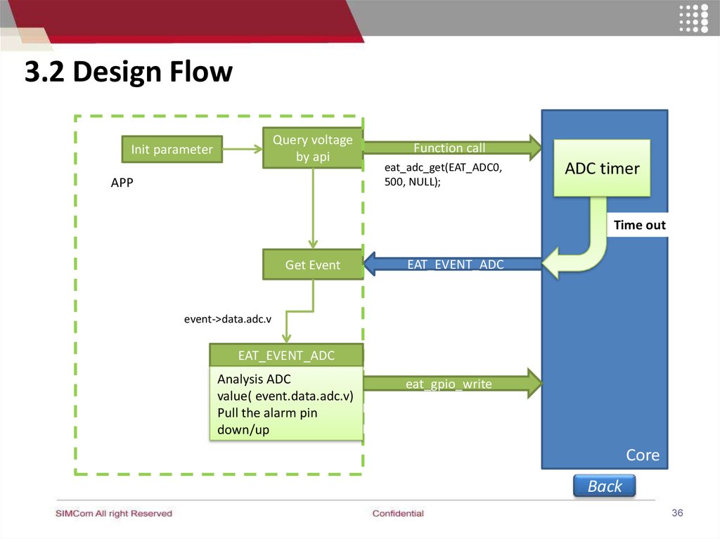
3.2 Design FlowQuery voltage
by api
Init parameter
APP
Function call
eat_adc_get(EAT_ADC0,
500, NULL);
ADC timer
Time out
Get Event
EAT_EVENT_ADC
event->data.adc.v
EAT_EVENT_ADC
Analysis ADC
value( event.data.adc.v)
Pull the alarm pin
down/up
eat_gpio_write
Core
Back
36
37.
Thanks!37