


 programming
Similar presentations:


Assembly language
1.
Teaching
L C
ondon
omputing
CAS London CPD Day 2016
Little Man Computer
William Marsh
School of Electronic Engineering and Computer Science
Queen Mary University of London
2.
Overview and Aims• LMC is a computer simulator
• … understanding how a computer work
• To program the LMC, must understand:
• Memory addresses
• Instructions
• Fetch-execute cycle
• Practical exercises
• What we can learn from LMC
3.
What is in a Computer?• Memory
• CPU
• I/O
4.
Simple Computer• Processor
Memory
• CPU
• Memory
addresses
• Data
• Program
instructions
data
CPU
data
• I/O
• Keyboard
• Display
• Disk
Keyboard
I/F
Disk
I/F
Display
I/F
5.
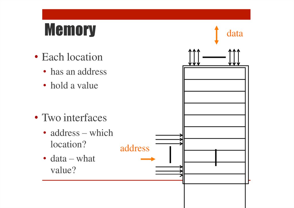
Memory• Each location
• has an address
• hold a value
• Two interfaces
• address – which
location?
address
• data – what
value?
data
6.
Quiz – What is theMemory?
7.
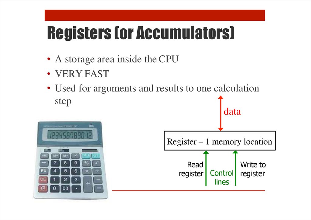
Registers (or Accumulators)• A storage area inside the CPU
• VERY FAST
• Used for arguments and results to one calculation
step
data
Register – 1 memory location
Read
Write to
register Control register
lines
8.
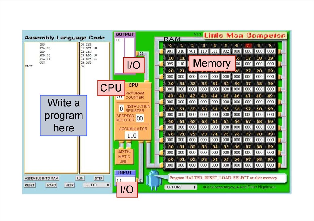
I/OCPU
Write a
program
here
I/O
Memory
9.
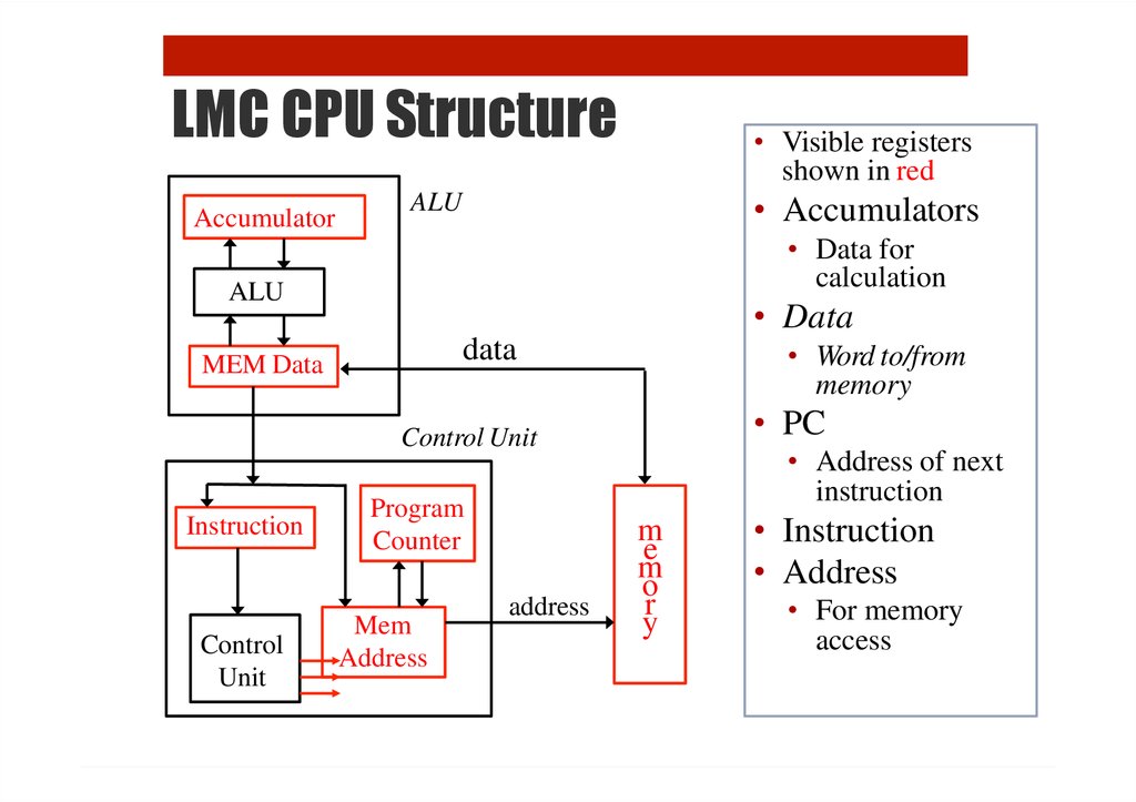
LMC CPU StructureAccumulator
• Visible registers
shown in red
• Accumulators
ALU
• Data for
calculation
ALU
• Data
data
MEM Data
• Word to/from
memory
• PC
Control Unit
Instruction
Control
Unit
Program
Counter
Mem
Address
address
• Address of next
instruction
m
e
m
o
r
y
• Instruction
• Address
• For memory
access
10.
InstructionsThe primitive language of a computer
11.
InstructionsOpCode
Address
• Instruction
• What to do: Opcode
• Where: memory address
• Instructions for arithmetic
• Add, Multiply, Subtract
• Memory instructions
• LOAD value from memory
• STORE value in memory
• The instructions are
very simple
• Each make of
computer has
different instructions
• Programs in a highlevel language can
work on all
computers
12.
InstructionsOpCode
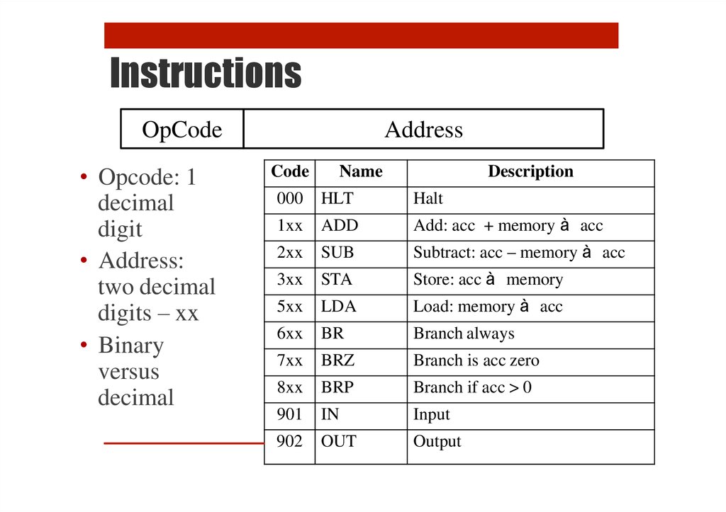
• Opcode: 1
decimal
digit
• Address:
two decimal
digits – xx
• Binary
versus
decimal
Address
Code
Name
Description
000
HLT
Halt
1xx
ADD
Add: acc + memory à acc
2xx
SUB
Subtract: acc – memory à acc
3xx
STA
Store: acc à memory
5xx
LDA
Load: memory à acc
6xx
BR
Branch always
7xx
BRZ
Branch is acc zero
8xx
BRP
Branch if acc > 0
901
IN
Input
902
OUT
Output
13.
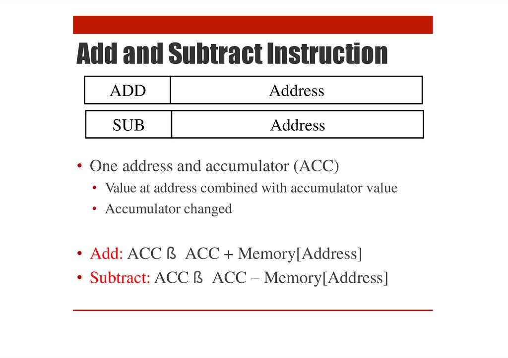
Add and Subtract InstructionADD
Address
SUB
Address
• One address and accumulator (ACC)
• Value at address combined with accumulator value
• Accumulator changed
• Add: ACC ß ACC + Memory[Address]
• Subtract: ACC ß ACC – Memory[Address]
14.
Load and Store InstructionLDA
Address
STA
Address
• Move data between memory and accumulator
(ACC)
• Load: ACC ß Memory[Address]
• Store: Memory[Address] ß ACC
15.
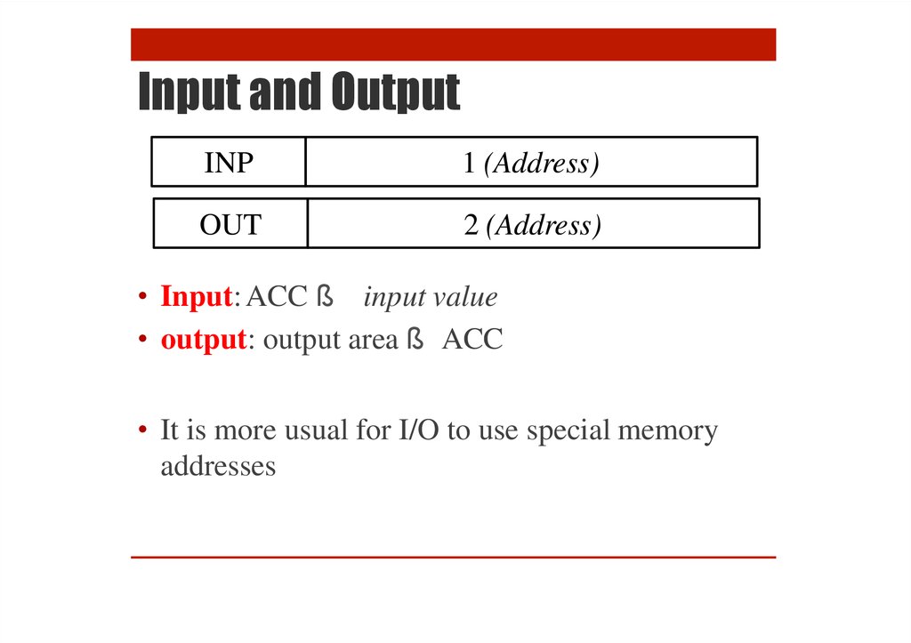
Input and OutputINP
1 (Address)
OUT
2 (Address)
• Input: ACC ß input value
• output: output area ß ACC
• It is more usual for I/O to use special memory
addresses
16.
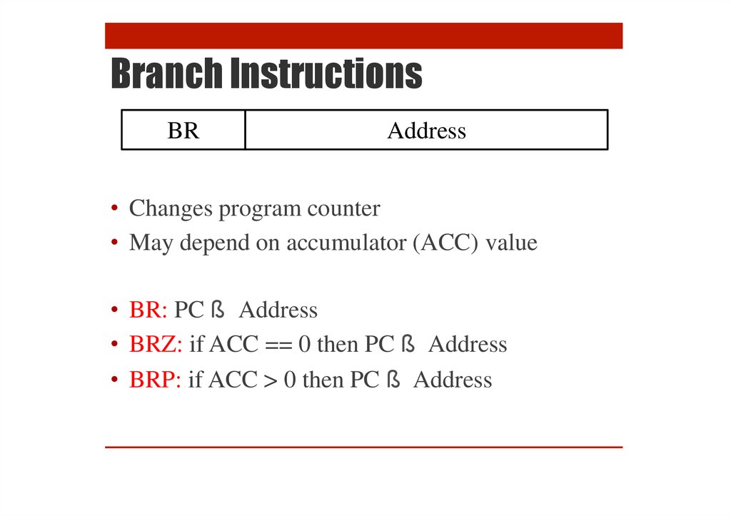
Branch InstructionsBR
Address
• Changes program counter
• May depend on accumulator (ACC) value
• BR: PC ß Address
• BRZ: if ACC == 0 then PC ß Address
• BRP: if ACC > 0 then PC ß Address
17.
Assembly CodeNumbers
• Instructions in text
• Instruction name: STA,
LDA
• Memory holds numbers
• Opcode: 0 to 9
• Address: 00 to 99
• Address: name using
DAT
Line
1
2
3
4
5
6
7
Location
INP
STA x
INP
STA y
HLT
x DAT
y DAT
ASSEMBLE
00
01
02
03
04
05
06
9 01
3 05
9 01
3 06
0 00
(used for x)
(used for y)
18.
LMC Example19.
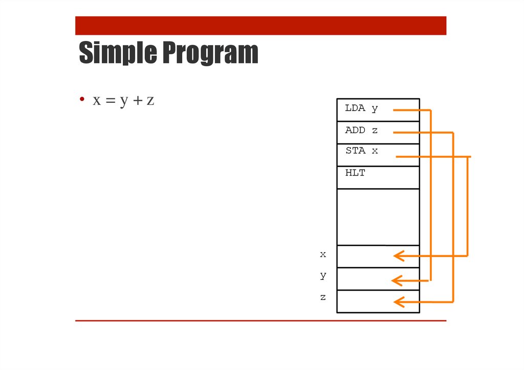
Simple Program• x=y+z
LDA y
ADD z
STA x
HLT
x
y
z
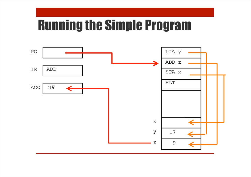
20.
Running the Simple ProgramLDA y
PC
ADD z
IR
ACC
LDA
STA x
HLT
17
x
y
17
z
9
21.
Running the Simple ProgramLDA y
PC
ADD z
IR
ACC
ADD
STA x
HLT
2167
x
y
17
z
9
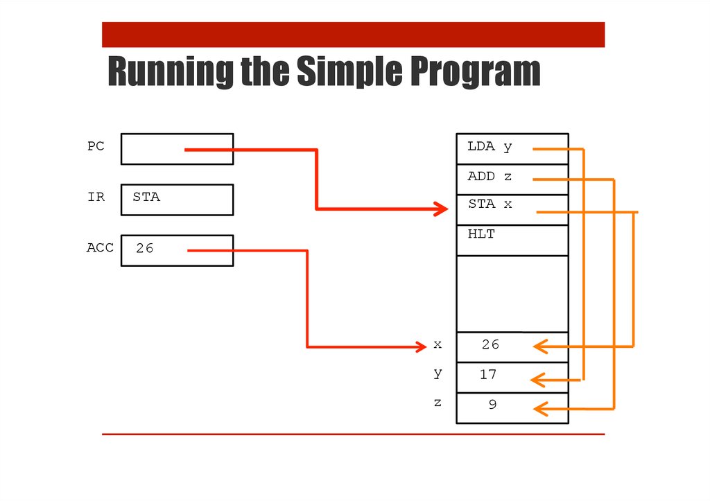
22.
Running the Simple ProgramLDA y
PC
ADD z
IR
ACC
STA
STA x
HLT
26
x
26
y
17
z
9
23.
Running the Simple ProgramLDA y
PC
ADD z
IR
ACC
HLT
STA x
HLT
26
x
26
y
17
z
9
24.
Practice Exercises• Try the first three exercises on the practical sheet
25.
Fetch-Execute CycleHow the Computer Processes Instructions
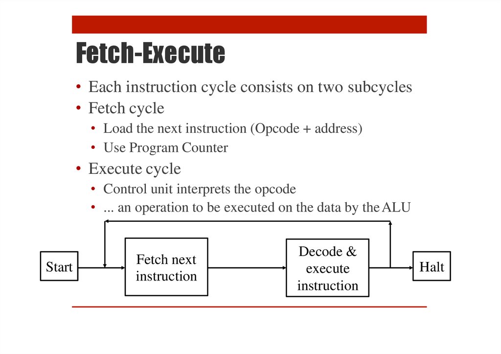
26.
Fetch-Execute• Each instruction cycle consists on two subcycles
• Fetch cycle
• Load the next instruction (Opcode + address)
• Use Program Counter
• Execute cycle
• Control unit interprets the opcode
• ... an operation to be executed on the data by the ALU
Start
Fetch next
instruction
Decode &
execute
instruction
Halt
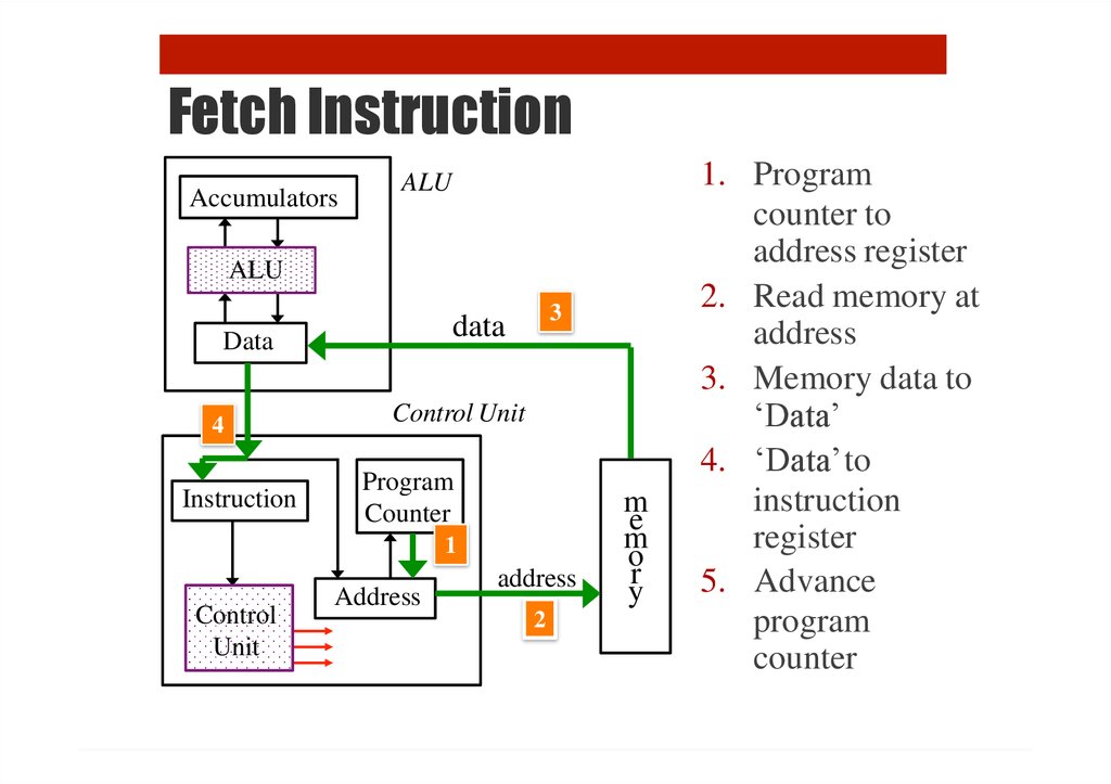
27.
Fetch InstructionAccumulators
ALU
ALU
Data
4
Instruction
3
data
Control Unit
Program
Counter
1
Control
Unit
Address
address
2
m
e
m
o
r
y
1. Program
counter to
address register
2. Read memory at
address
3. Memory data to
‘Data’
4. ‘Data’to
instruction
register
5. Advance
program
counter
28.
Execute InstructionAccumulators
6
ALU
5
ALU
5
4
data
Data
2
Instruction
Control Unit
Program
Counter
1
Control
Unit
Address
address
3
m
e
m
o
r
y
1. Decode instruction
2. Address from
instruction to
‘address register’
3. Access memory
4. Data from memory
to ‘data register’
5. Add (e.g.) data and
accumulator value
6. Update
accumulator
29.
What We Can Learn from LMC1. How programming language work
2. What a compiler does
3. Why we need an OS
30.
Understanding Variables and Assignment• What is a variable?
• What is on the left hand side of:
x = x + 1
31.
Understanding Variables and Assignment• What is a variable?
• What is on the left hand side of:
A[x+1] = 42
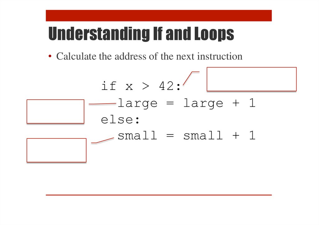
32.
Understanding If and Loops• Calculate the address of the next instruction
if x > 42:
large = large + 1
else:
small = small + 1
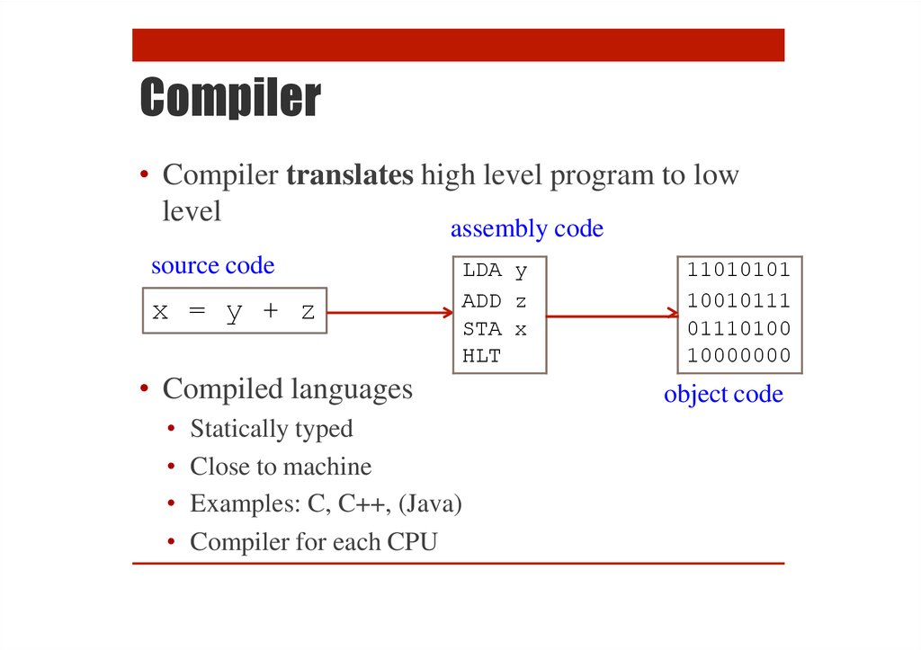
33.
Compiler• Compiler translates high level program to low
level
assembly code
source code
x = y + z
LDA y
ADD z
STA x
HLT
• Compiled languages
Statically typed
Close to machine
Examples: C, C++, (Java)
Compiler for each CPU
11010101
10010111
01110100
10000000
object code
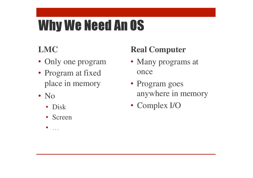
34.
Why We Need An OSLMC
• Only one program
• Program at fixed
place in memory
• No
• Disk
• Screen
• …
Real Computer
• Many programs at
once
• Program goes
anywhere in memory
• Complex I/O
35.
Summary of CPU Architecture• Memory contains data and program
• Program counter: address of next instruction
• Instructions represented in binary
• Each instruction has an ‘opcode’
• Instructions contain addresses
• Addresses used to access data
• Computer does ‘fetch-execute’
• ‘Execute’ depends on opcode
• Computer can be built from < 10,000 electronic
switches (transistors)
36.
Project: Writing an LMCInterpreter
37.
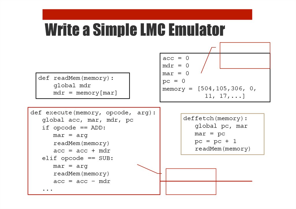
Write a Simple LMC Emulatordef readMem(memory):
global mdr
mdr = memory[mar]
def execute(memory, opcode, arg):
global acc, mar, mdr, pc
if opcode == ADD:
mar = arg
readMem(memory)
acc = acc + mdr
elif opcode == SUB:
mar = arg
readMem(memory)
acc = acc – mdr
...
acc = 0
mdr = 0
mar = 0
pc = 0
memory = [504,105,306, 0,
11, 17,...]
deffetch(memory):
global pc, mar
mar = pc
pc = pc + 1
readMem(memory)