


 industry
Similar presentations:


Simulation of wing-body junction flows with hybrid RANS/LES methods
1. Simulation of wing-body junction flows with hybrid RANS/LES methods
Authors: Song Fu *, Zhixiang Xiao, Haixin Chen, Yufei Zhang, Jingbo Huang2. Introduction
• Junction flow occurs when a boundary layer encounters anobstruction
• At realistic large Reynolds number, the adverse pressure gradient in
the streamwise direction imposed by the wing often causes the
upwind boundary layer on the body to separate and form multiple
horseshoe vortices around the wing
• Better understanding and accurate prediction of the junction flows
can effectively help the design of lower drag and high-efficiency flight
vehicles
3. Viewed objects
• Rood wing-body junction (3:2 elliptical nose and a NACA 0020 tailmodel) – have experimental results
• NASA TN D-712 – has interference flows at high angles of attack with
a low-Re two-equation k–g model which requires no parameterization
of the distance to the wall
4. Numerical methods. Flow equations
• The computations here are all based on a compressible solver using aRoe flux-difference splitting scheme with a 3rd order monotone
upstream scheme
• A modified fully implicit lower–upper symmetric Gaussian Seidel
(LUSGS, Yoon and Jameson, 1987; Xiao et al., 2006) model with
Newton-like sub-iteration in pseudo time is taken as the time
marching method when solving the mean flow and the turbulence
model equations
• Global non-dimensional time stepping is implemented to capture the
unsteady properties of the separation flows
5. Numerical methods. Energy and dissipation equations
• Using the LU-SGS method• The production terms are treated explicitly, lagged in time while the
dissipation and diffusion terms are treated implicitly
• The advective terms are discretized using second order upwind
scheme. The diffusive terms are discretized using a second-order
central scheme.
6. Results. Rood
Boundary conditions:• at x/T = -18.24: inlet (from
experiment)
• at x/T = 16: outflow (zero
streamwise gradients)
• at y/T = 0, y/T = 7 and z/T = 3:
symmetric
• at z/T = 0: wall (no-slip)
7. Difference between SST and WD+
Comparisons on U and k with the WD+ and SST8. Difference on grid
Comparisons on U/Uref and k/U2ref based on two grids9. Flowfields on the symmetric plane
Comparison of velocity vectors on the symmetric plane10. Flow structures at three streamwise positions
Transverse velocity at different streamwise positions (maximum thickness, middle and trailing edgeof the wing)
11. Flow structures at three streamwise positions
Flow patterns around the wing-body junction (a) shear stress lines and vortex in the wake; (b)upwind symmetry plane horseshoe vortex and (c) vortices near the trailing edge
12. Flow structures at three streamwise positions
Comparisons of turbulent kinetic energy and cross-streamwise normal stress near the trailing edge (x/T = 3.95)13. Flowfields in the wake
Comparisons of turbulent kinetic energy and the vertical flow vectors in the wake (x/T = 6.38)14. Results. TN D-712 junction
Grids around TN D-712 Wing-fuselage junction.15. Computation parameters
• Mach number - 0.9• Reynolds number is 7.5 · 106 (based on halfspan)
• Angle of attack is 12.5o
16. Pressure coefficients
Comparisons of pressure coefficients of different turbulence methods near the junction17. Vortex over the wing
Comparison on vortex over the wing with RANS, DES and DDES methods.18.
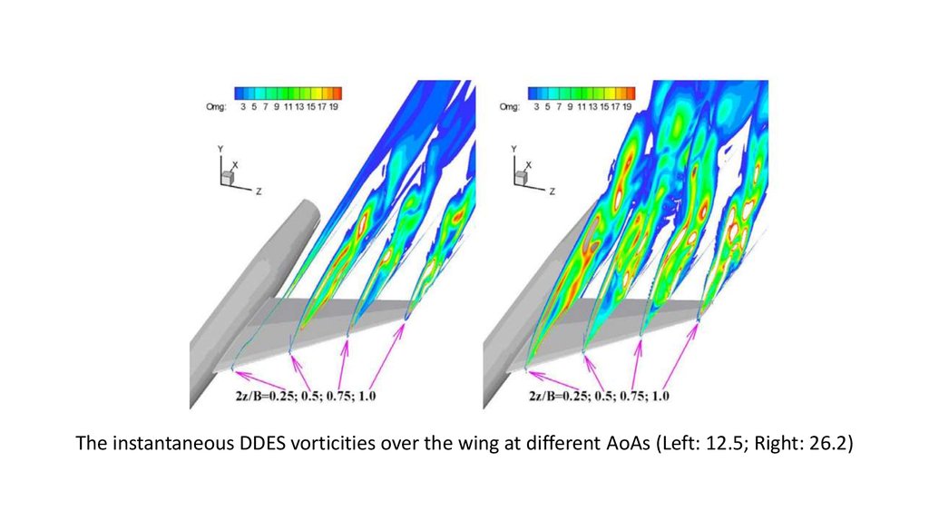
The instantaneous DDES vorticities over the wing at different AoAs (Left: 12.5; Right: 26.2)19. Flow patterns of DDES
Transverse flow structure at different streamwise positions by DDES. 2x/B = 1.667, 1.833, 2.167 and2.500.
20. Conclusion
• Weakly nonlinear correction k–x model (WD+) can effectively predictthe flows past wing-body junctions with adverse pressure gradients at
zero and middle angle of attack
• But one has to go to DDES to capture the large eddies detached from
the leading edge of the wing in NASA TN D-712 case at 12.5o angle of
attack
• DES delivers the primary horseshoe vortex for the Rood case and the
vortex breakdown for the TN D-712 case too far upstream as
compared to the measurements
• Among the models studied here DDES provides a reliable tool in the
modeling of the wing-body junction flows