


 physics
 english
Similar presentations:


Internal сombustion engine. Thermodynamic analysis. Engine cycles
1. Internal Сombustion Engine
Thermodynamic analysisEngine Cycles
Aleksey Terentyev
1
2. Basic terms and definitions
An ideal gas is a theoretical gas composed of a set of randomly moving, noninteracting point particles. The ideal gas concept is useful because it obeys theideal gas law, a simplified equation of state, and is amenable to analysis under
statistical mechanics.
Enthalpy is a measure of the total energy of a thermodynamic system. It
includes the internal energy, which is the energy required to create a system,
and the amount of energy required to make room for it by displacing its
environment and establishing its volume and pressure.
An isentropic process or isoentropic process is one in which, for purposes of
engineering analysis and calculation, one may assume that the process takes
place from initiation to completion without an increase or decrease in the
entropy of the system, i.e., the entropy of the system remains constant. It can be
proven that any reversible adiabatic process is an isentropic process. A simple
more common definition of isentropic would be "No change in entropy".
Entropy in statistical mechanics is a measure of the number of specific ways in
which a system may be arranged, often taken to be a measure of "disorder"; the
higher the entropy, the higher the disorder. The entropy of an isolated system
never decreases, because isolated systems spontaneously evolve towards
thermodynamic equilibrium – the state of maximum entropy.
Entropy is a mathematically-defined thermodynamic quantity that helps to
account for the flow of energy through a thermodynamic process.
2
3. Basic terms and definitions
specific volume of gas - удельный объем газа;specific enthalpy - удельная энтальпия;
specific internal energy - удельная внутренняя энергия;
specific heats – теплоемкости;
specific work – удельная работа;
mass flow rate - eдельный массовый расход;
heat transfer rate for unit mass - теплопроизводительность для единицы
массы;
heat transfer rate - скорость теплопередачи;
WOT (Wide-Open Throttle) – полностью открытый дроссель;
Bottom-Dead-Center (BDC);
Top-Dead-Center (TDC);
When an occurrence in a cycle happens before TDC, it is often abbreviated
bTDC or bTe;
When the occurrence happens after TDC, it will be abbreviated aTDC or aTe;
During an engine cycle things can happen before bottom-dead-center, bBDC or
bBC, and after bottom-dead-center, aBDC or aBe;
crevice flow – щелевой поток;
blowby – прорыв газов;
3
4. ENGINE CYCLES
This chapter studies the basic cycles used in reciprocatinginternal combustion engines, both four stroke and two stroke.
The most common four-stroke SI and CI cycles are
analyzed in detail using air-standard analysis.
4
5. WORK
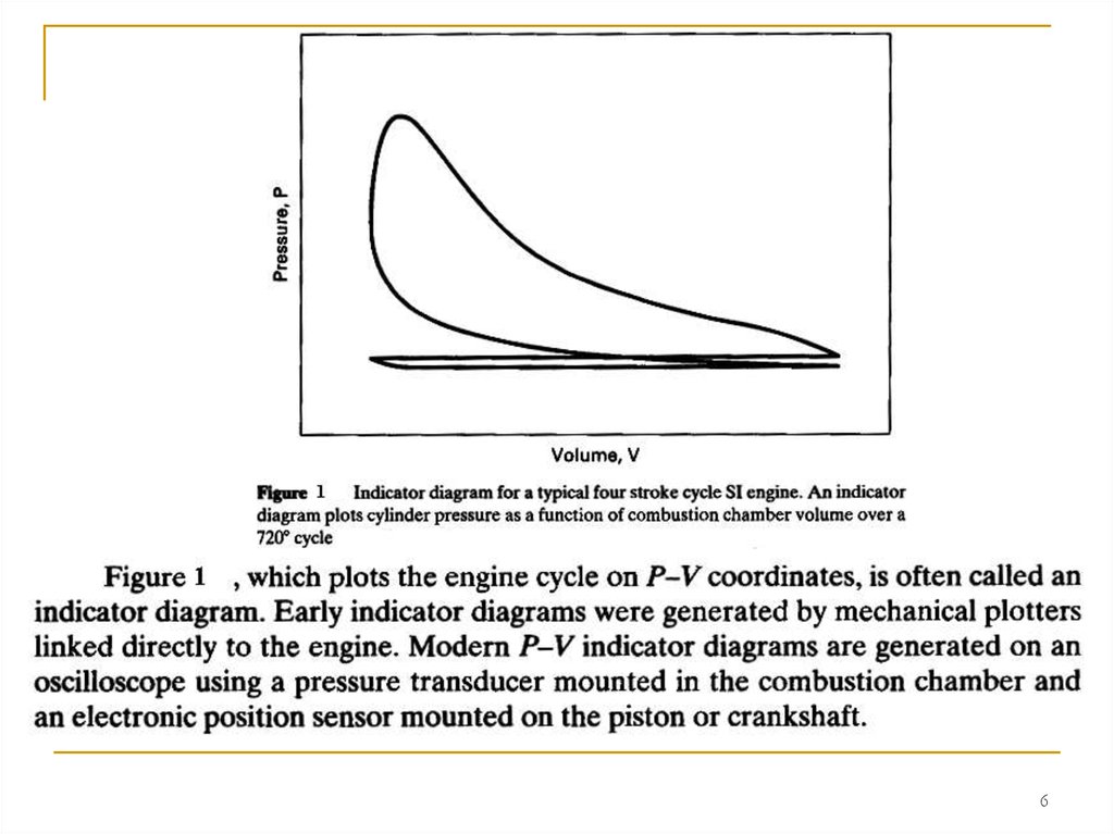
56.
67.
78.
89.
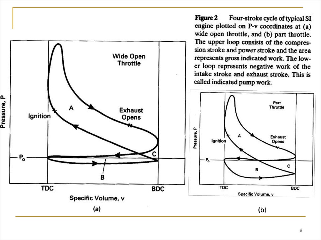
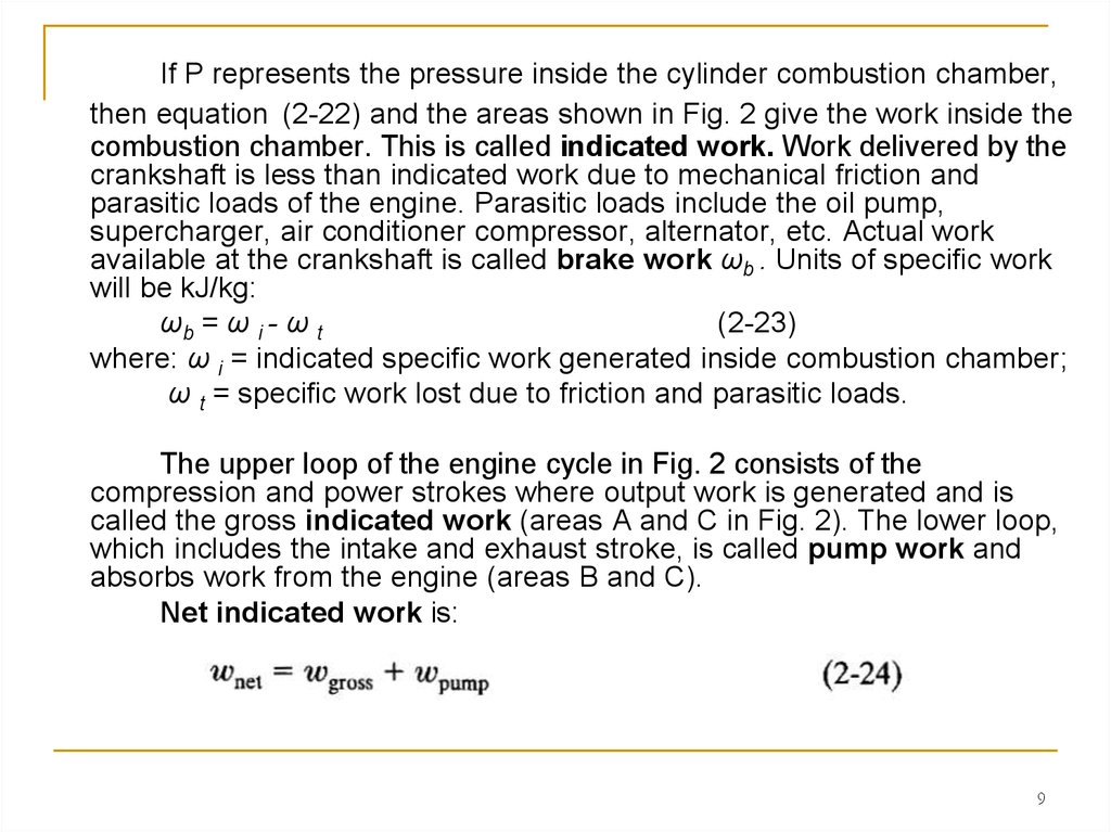
If P represents the pressure inside the cylinder combustion chamber,then equation (2-22) and the areas shown in Fig. 2 give the work inside the
combustion chamber. This is called indicated work. Work delivered by the
crankshaft is less than indicated work due to mechanical friction and
parasitic loads of the engine. Parasitic loads include the oil pump,
supercharger, air conditioner compressor, alternator, etc. Actual work
available at the crankshaft is called brake work ωb . Units of specific work
will be kJ/kg:
ωb = ω i - ω t
(2-23)
where: ω i = indicated specific work generated inside combustion chamber;
ω t = specific work lost due to friction and parasitic loads.
The upper loop of the engine cycle in Fig. 2 consists of the
compression and power strokes where output work is generated and is
called the gross indicated work (areas A and C in Fig. 2). The lower loop,
which includes the intake and exhaust stroke, is called pump work and
absorbs work from the engine (areas B and C).
Net indicated work is:
9
10.
1011.
It then decreases withdecreasing engine speed to zero
at idle conditions, when no work
is taken off the crankshaft.
Care should be taken
when using the terms "gross
work" and "net work". In some
older literature and textbooks, net
work (or net power) meant the
output of an engine with all
components, while gross work
(or gross power) meant the
output of the engine with fan and
exhaust system removed.
11
12. AIR-STANDARD CYCLES
The cycle experienced in the cylinder of an internal combustionengine is very complex.
First, air (CI engine) or air mixed with fuel (SI engine) is ingested
and mixed with the slight amount of exhaust residue remaining from
the previous cycle. This mixture is then compressed and combusted,
changing the composition to exhaust products consisting largely of
CO2, H20, and N2 with many other lesser components.
Then, after an expansion process, the exhaust valve is opened
and this gas mixture is expelled to the surroundings. Thus, it is an
open cycle with changing composition, a difficult system to analyze.
To make the analysis of the engine cycle much more manageable,
the real cycle is approximated with an ideal air-standard cycle which
differs from the actual by the following:
12
13. AIR-STANDARD CYCLES
1. The gas mixture in the cylinder is treated as air for the entire cycle, andproperty values of air are used in the analysis. This is a good approximation during
the first half of the cycle, when most of the gas in the cylinder is air with only up to
about 7% fuel vapor. Even in the second half of the cycle, when the gas composition is mostly CO2, H20, and N2, using air properties does not create large errors
in the analysis. Air will be treated as an ideal gas with constant specific heats.
2. The real open cycle is changed into a closed cycle by assuming that the
gases being exhausted are fed back into the intake system. This works with ideal
air-standard cycles, as both intake gases and exhaust gases are air. Closing the
cycle simplifies the analysis.
3. The combustion process is replaced with a heat addition term Qin of equal
energy value. Air alone cannot combust.
4. The open exhaust process, which carries a large amount of enthalpy out of
the system, is replaced with a closed system heat rejection process Qout of equal
energy value.
5. Actual engine processes are approximated with ideal processes.
(a) The almost-constant-pressure intake and exhaust strokes are
assumed to be constant pressure. At WOT (Wide-Open Throttle), the intake
stroke is assumed to be at a pressure Po of one atmosphere. At partially
closed throttle or when supercharged, inlet pressure will be some constant
value other than one atmosphere. The exhaust stroke pressure is assumed
constant at one atmosphere.
13
14. AIR-STANDARD CYCLES
(b) Compression strokes and expansion strokes are approximated byisentropic processes. To be truly isentropic would require these strokes to be
reversible and adiabatic. There is some friction between the piston and
cylinder walls but, because the surfaces are highly polished and lubricated,
this friction is kept to a minimum and the processes are close to frictionless
and reversible. If this were not true, automobile engines would wear out long
before the 150-200 thousand miles which they now last if properly maintained.
There is also fluid friction because of the gas motion within the cylinders during
these strokes. This too is minimal. Heat transfer for anyone stroke will be
negligibly small due to the very short time involved for that single process.
Thus, an almost reversible and almost adiabatic process can quite accurately
be approximated with an isentropic process.
(c) The combustion process is idealized by a constant-volume process
(SI cycle), a constant-pressure process (CI cycle), or a combination of both (CI
Dual cycle).
(d) Exhaust blowdown is approximated by a constant-volume process.
(e) All processes are considered reversible.
14
15.
In air-standard cycles, air is considered an ideal gas suchthat the following ideal gas relationships can be used:
15
16.
1617.
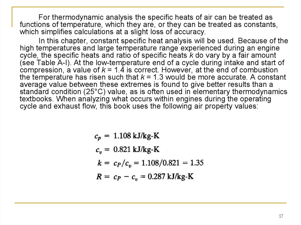
For thermodynamic analysis the specific heats of air can be treated asfunctions of temperature, which they are, or they can be treated as constants,
which simplifies calculations at a slight loss of accuracy.
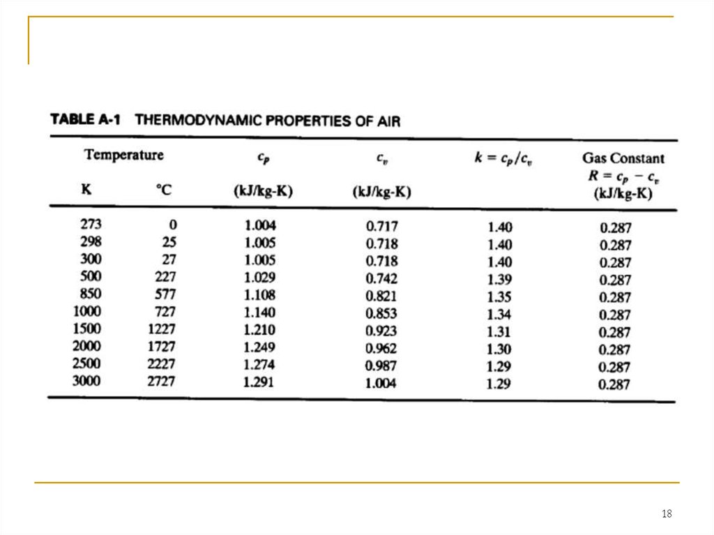
In this chapter, constant specific heat analysis will be used. Because of the
high temperatures and large temperature range experienced during an engine
cycle, the specific heats and ratio of specific heats k do vary by a fair amount
(see Table A-I). At the low-temperature end of a cycle during intake and start of
compression, a value of k = 1.4 is correct. However, at the end of combustion
the temperature has risen such that k = 1.3 would be more accurate. A constant
average value between these extremes is found to give better results than a
standard condition (25°C) value, as is often used in elementary thermodynamics
textbooks. When analyzing what occurs within engines during the operating
cycle and exhaust flow, this book uses the following air property values:
17
18.
1819.
1920. OTTO CYCLE
The cycle of a four-stroke, SI, naturally aspirated engine at WOT is shownin Fig. 4. This is the cycle of most automobile engines and other four-stroke SI
engines. For analysis, this cycle is approximated by the air-standard cycle shown in
Fig. 5. This ideal air-standard cycle is called an Otto cycle, named after one of the
early developers of this type of engine.
The intake stroke of the Otto cycle starts with the piston at TDC and is a
constant-pressure process at an inlet pressure of one atmosphere (process 6-1 in
Fig. 5).
This is a good approximation to the
inlet process of a real engine at WOT,
which will actually be at a pressure slightly
less than atmospheric due to pressure
losses in the inlet air flow. The
temperature of the air during the inlet
stroke is increased as the air passes
through the hot intake manifold. The
temperature at point 1 will generally be on
the order of 25° to 35°C hotter than the
surrounding air temperature.
20
21.
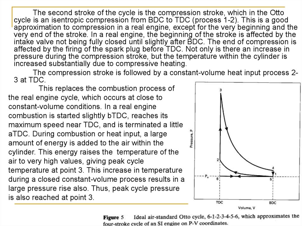
The second stroke of the cycle is the compression stroke, which in the Ottocycle is an isentropic compression from BDC to TDC (process 1-2). This is a good
approximation to compression in a real engine, except for the very beginning and the
very end of the stroke. In a real engine, the beginning of the stroke is affected by the
intake valve not being fully closed until slightly after BDC. The end of compression is
affected by the firing of the spark plug before TDC. Not only is there an increase in
pressure during the compression stroke, but the temperature within the cylinder is
increased substantially due to compressive heating.
The compression stroke is followed by a constant-volume heat input process 23 at TDC.
This replaces the combustion process of
the real engine cycle, which occurs at close to
constant-volume conditions. In a real engine
combustion is started slightly bTDC, reaches its
maximum speed near TDC, and is terminated a little
aTDC. During combustion or heat input, a large
amount of energy is added to the air within the
cylinder. This energy raises the temperature of the
air to very high values, giving peak cycle
temperature at point 3. This increase in temperature
during a closed constant-volume process results in a
large pressure rise also. Thus, peak cycle pressure
is also reached at point 3.
21
22.
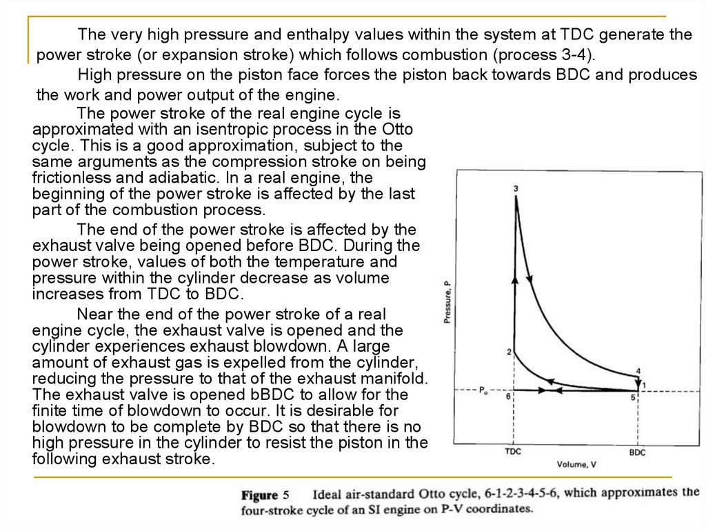
The very high pressure and enthalpy values within the system at TDC generate thepower stroke (or expansion stroke) which follows combustion (process 3-4).
High pressure on the piston face forces the piston back towards BDC and produces
the work and power output of the engine.
The power stroke of the real engine cycle is
approximated with an isentropic process in the Otto
cycle. This is a good approximation, subject to the
same arguments as the compression stroke on being
frictionless and adiabatic. In a real engine, the
beginning of the power stroke is affected by the last
part of the combustion process.
The end of the power stroke is affected by the
exhaust valve being opened before BDC. During the
power stroke, values of both the temperature and
pressure within the cylinder decrease as volume
increases from TDC to BDC.
Near the end of the power stroke of a real
engine cycle, the exhaust valve is opened and the
cylinder experiences exhaust blowdown. A large
amount of exhaust gas is expelled from the cylinder,
reducing the pressure to that of the exhaust manifold.
The exhaust valve is opened bBDC to allow for the
finite time of blowdown to occur. It is desirable for
blowdown to be complete by BDC so that there is no
high pressure in the cylinder to resist the piston in the
following exhaust stroke.
22
23.
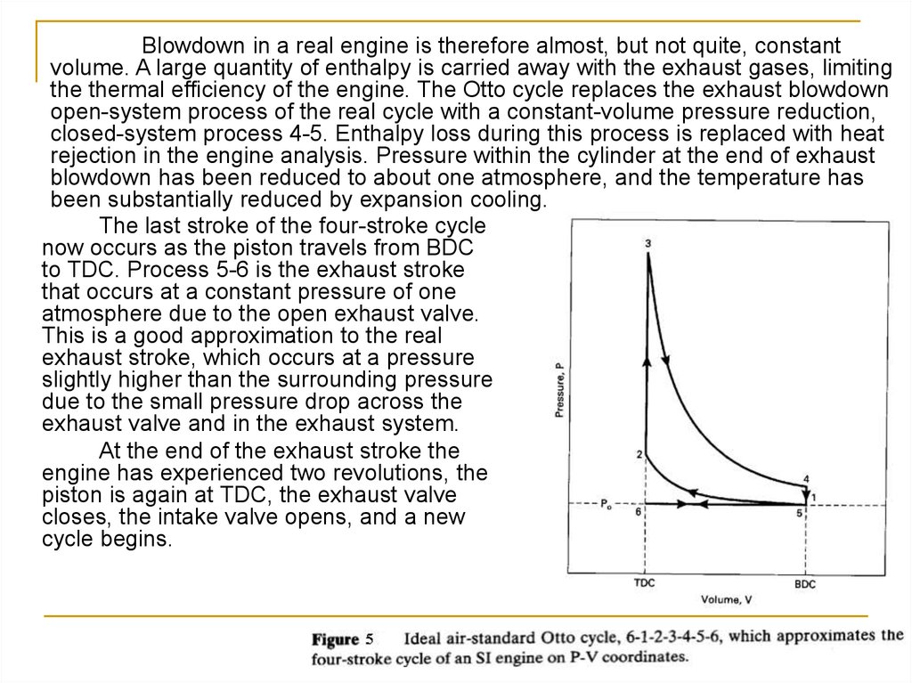
Blowdown in a real engine is therefore almost, but not quite, constantvolume. A large quantity of enthalpy is carried away with the exhaust gases, limiting
the thermal efficiency of the engine. The Otto cycle replaces the exhaust blowdown
open-system process of the real cycle with a constant-volume pressure reduction,
closed-system process 4-5. Enthalpy loss during this process is replaced with heat
rejection in the engine analysis. Pressure within the cylinder at the end of exhaust
blowdown has been reduced to about one atmosphere, and the temperature has
been substantially reduced by expansion cooling.
The last stroke of the four-stroke cycle
now occurs as the piston travels from BDC
to TDC. Process 5-6 is the exhaust stroke
that occurs at a constant pressure of one
atmosphere due to the open exhaust valve.
This is a good approximation to the real
exhaust stroke, which occurs at a pressure
slightly higher than the surrounding pressure
due to the small pressure drop across the
exhaust valve and in the exhaust system.
At the end of the exhaust stroke the
engine has experienced two revolutions, the
piston is again at TDC, the exhaust valve
closes, the intake valve opens, and a new
cycle begins.
23
24.
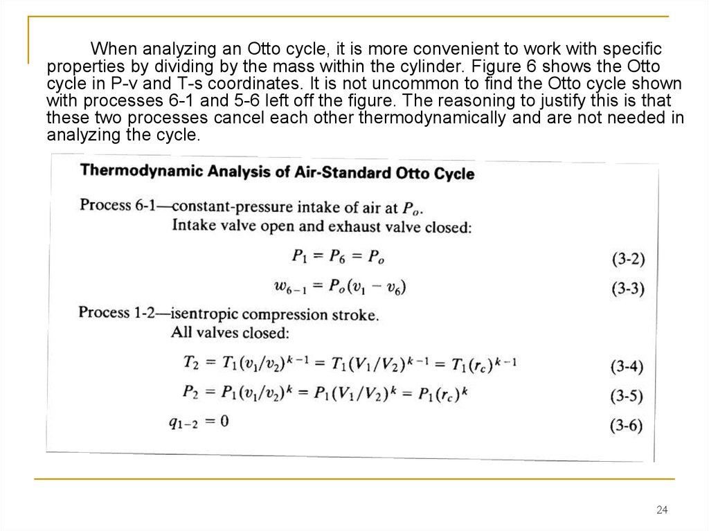
When analyzing an Otto cycle, it is more convenient to work with specificproperties by dividing by the mass within the cylinder. Figure 6 shows the Otto
cycle in P-v and T-s coordinates. It is not uncommon to find the Otto cycle shown
with processes 6-1 and 5-6 left off the figure. The reasoning to justify this is that
these two processes cancel each other thermodynamically and are not needed in
analyzing the cycle.
24
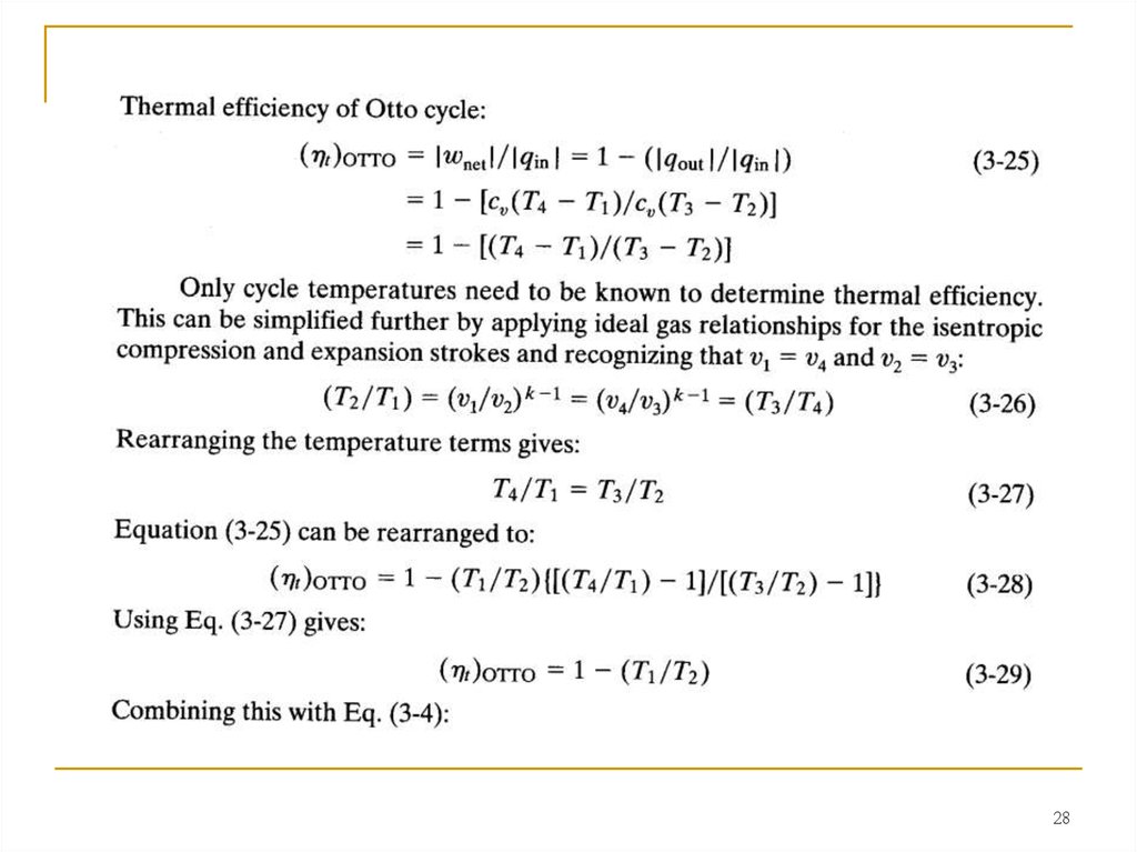
25.
2526.
2627.
2728.
2829.
2930. REAL AIR-FUEL ENGINE CYCLES
The actual cycle experienced by an internal combustion engine is not, inthe true sense, a thermodynamic cycle. An ideal air-standard thermodynamic
cycle occurs on a closed system of constant composition. This is not what
actually happens in an IC engine, and for this reason air-standard analysis
gives, at best, only approximations to actual conditions and outputs. Major
differences include:
1. Real engines operate on an open cycle with changing composition.
Not only does the inlet gas composition differ from what exits, but often the
mass flow rate is not the same. Those engines which add fuel into the
cylinders after air induction is complete (CI engines and some SI engines)
change the amount of mass in the gas composition part way through the cycle.
There is a greater gaseous mass exiting the engine in the exhaust than what
entered in the induction process. This can be on the order of several percent.
Other engines carry liquid fuel droplets with the inlet air which are idealized as
part of the gaseous mass in air-standard analysis. During combustion, total
mass remains about the same but molar quantity changes. Finally, there is a
loss of mass during the cycle due to crevice flow and blowby past the pistons.
Most of crevice flow is a temporary loss of mass from the cylinder, but
because it is greatest at the start of the power stroke, some output work is lost
during expansion. Blowby can decrease the amount of mass in the cylinders
by as much as 1% during compression and combustion.
30
31.
2. Air-standard analysis treats the fluid flow through the entire engine as air andapproximates air as an ideal gas. In a real engine inlet flow may be all air, or it may be
air mixed with up to 7% fuel, either gaseous or as liquid droplets, or both. During
combustion the composition is then changed to a gas mixture of mostly CO2, H20, and
N2, with lesser amounts of CO and hydrocarbon vapor. In CI engines there will also be
solid carbon particles in the combustion products gas mixture. Approximating exhaust
products as air simplifies analysis but introduces some error.
Even if all fluid in an engine cycle were air, some error would be introduced by
assuming it to be an ideal gas with constant specific heats in air-standard analysis. At
the low pressures of inlet and exhaust, air can accurately be treated as an ideal gas,
but at the higher pressures during combustion, air will deviate from ideal gas behavior.
A more serious error is introduced by assuming constant specific heats for the
analysis. Specific heats of a gas have a fairly strong dependency on temperature and
can vary as much as 30% in the temperature range of an engine (for air, cp = 1.004
kJ/kg-K at 300 K and cp = 1.292 kJ/kg-K at 3000 K.
3. There are heat losses during the cycle of a real engine which are neglected in
air-standard analysis. Heat loss during combustion lowers actual peak temperature and
pressure from what is predicted. The actual power stroke, therefore, starts at a lower
pressure, and work output during expansion is decreased. Heat transfer continues
during expansion, and this lowers the temperature and pressure below the ideal
isentropic process towards the end of the power stroke. The result of heat transfer is a
lower indicated thermal efficiency than predicted by air-standard analysis. Heat transfer
is also present during compression, which deviates the process from isentropic.
However, this is less than during the expansion stroke due to the lower temperatures at
this time.
31
32.
4. Combustion requires a short but finite time to occur, and heat additionis not instantaneous at TDC, as approximated in an Otto cycle. A fast but finite
flame speed is desirable in an engine. This results in a finite rate of pressure
rise in the cylinders, a steady force increase on the piston face, and a smooth
engine cycle. A supersonic detonation would give almost instantaneous heat
addition to a cycle, but would result in a.rough cycle and quick engine
destruction. Because of the finite time required, combustion is started before
TDC and ends after TDC, not at constant volume as in air-standard analysis. By
starting combustion bTDC, cylinder pressure increases late in the compression
stroke, requiring greater negative work in that stroke. Because combustion is not
completed until aTDC, some power is lost at the start of the expansion stroke
(see Fig. 1). Another loss in the combustion process of an actual engine occurs
because combustion efficiency is less than 100%. This happens because of less
than perfect mixing, local variations in temperature and air-fuel due to
turbulence, flame quenching, etc. SI engines will generally have a combustion
efficiency of about 95%, while CI engines are generally about 98% efficient.
5. The blowdown process requires a finite real time and a finite cycle time,
and does not occur at constant volume as in air-standard analysis. For this
reason, the exhaust valve must open 40° to 60° bBDC, and output work at the
latter end of expansion is lost.
6. In an actual engine, the intake valve is not closed until after bottomdead center at the end of the intake stroke. Because of the flow restriction of the
valve, air is still entering the cylinder at BDC, and volumetric efficiency would be
lower if the valve closed here. Because of this, however, actual compression
does not start at BDC but only after the inlet valve closes. With ignition then
occurring before top dead-center, temperature and pressure rise before
combustion is less than predicted by air-standard analysis.
32
33.
7. Engine valves require a finite time to actuate. Ideally, valves would open andclose instantaneously, but this is not possible when using a camshaft. Cam profiles
must allow for smooth interaction with the cam follower, and this results in fast but finite
valve actuation. To assure that the intake valve is fully open at the start of the induction
stroke, it must start to open before TDC. Likewise, the exhaust valve must remain fully
open until the end of the exhaust stroke, with final closure occurring after TDC. The
resulting valve overlap period causes a deviation from the ideal cycle.
Because of these differences which real air-fuel cycles have from the ideal
cycles, results from air-standard analysis will have errors and will deviate from actual
conditions. Interestingly, however, the errors are not great, and property values of
temperature and pressure are very representative of actual engine values, depending
on the geometry and operating conditions of the real engine. By changing operating
variables such as inlet temperature and/or pressure, compression ratio, peak
temperature, etc., in Otto cycle analysis, good approximations can be obtained for
output changes that will Occur in a real engine as these variables are changed. Good
approximation of power output, thermal efficiency, and mep can be expected.
Indicated thermal efficiency of a real four-stroke SI engine is always somewhat
less than what air-standard Otto cycle analysis predicts. This is caused by the heat
losses, friction, ignition timing, valve timing, finite time of combustion and blowdown,
and deviation from ideal gas behavior of the real engine. Reference shows that over a
large range of operating variables the indicated thermal efficiency of an actual SI fourstroke cycle engine can be approximated by:
(T/t)actual = 0.85 (T/t)OTTO
(3-32)
This will be correct to within a few percent for large ranges of air-fuel equivalence
ratio, ignition timing, engine speed, compression ratio, inlet pressure, exhaust
pressure, and valve timing.
33
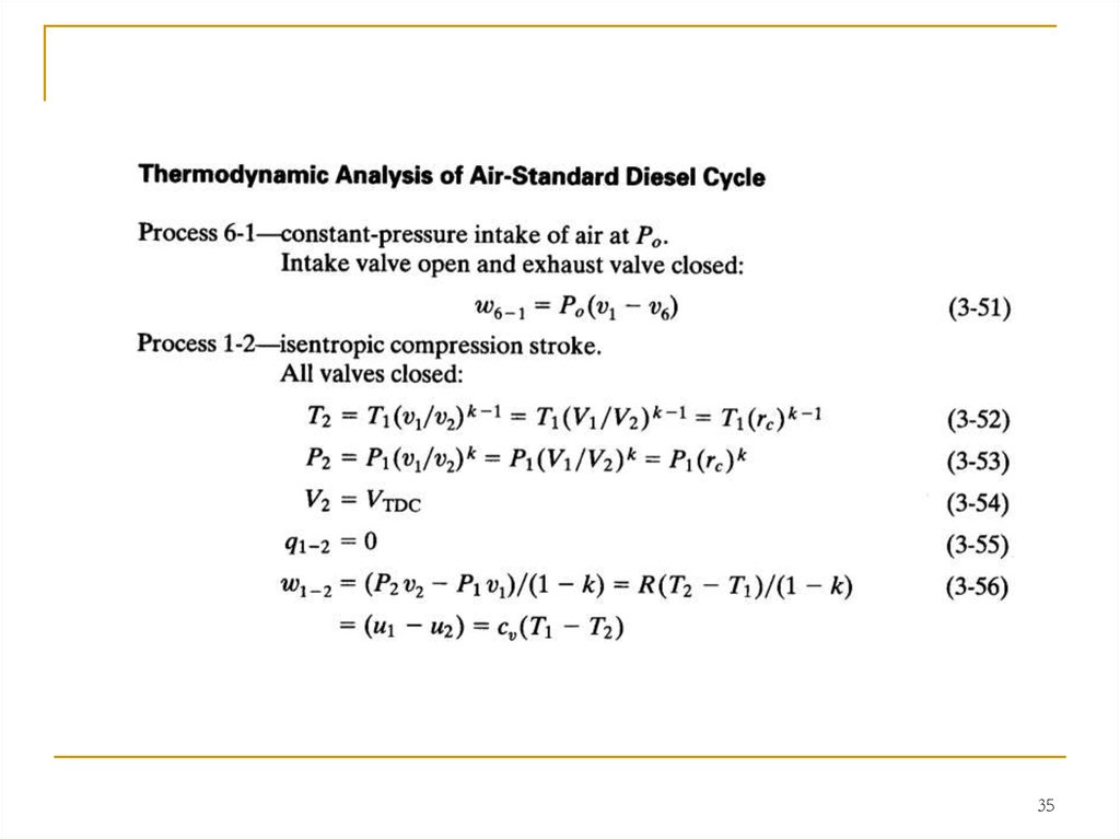
34. DIESEL CYCLE
Early CI engines injected fuel into the combustion chamber very latein the compression stroke, resulting in the indicator diagram shown in Fig. 8.
Due to ignition delay and the finite time required to inject the fuel, combustion
lasted into the expansion stroke.
This kept the pressure
at peak levels well past
TDC. This combustion
process is best
approximated as a constantpressure heat input in an
air-standard cycle, resulting
in the Diesel cycle shown in
Fig. 9. The rest of the cycle
is similar to the air-standard
Otto cycle. The diesel cycle
is sometimes called a
Constant Pressure cycle.
34
35.
3536.
3637.
3738.
3839.
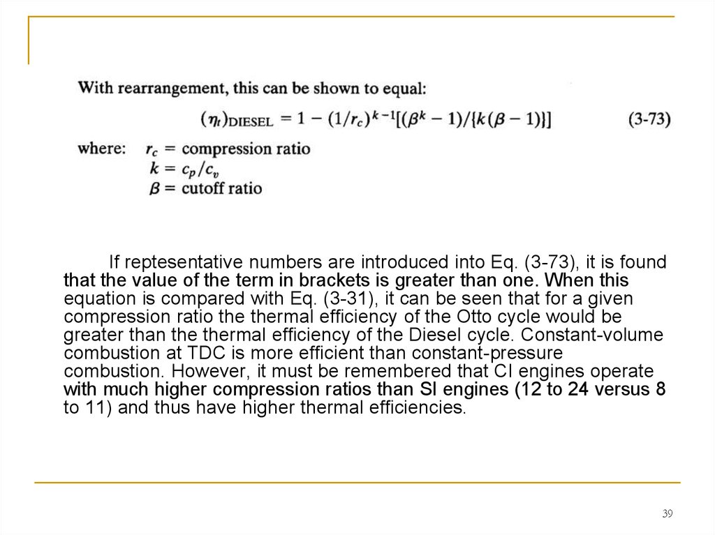
If reptesentative numbers are introduced into Eq. (3-73), it is foundthat the value of the term in brackets is greater than one. When this
equation is compared with Eq. (3-31), it can be seen that for a given
compression ratio the thermal efficiency of the Otto cycle would be
greater than the thermal efficiency of the Diesel cycle. Constant-volume
combustion at TDC is more efficient than constant-pressure
combustion. However, it must be remembered that CI engines operate
with much higher compression ratios than SI engines (12 to 24 versus 8
to 11) and thus have higher thermal efficiencies.
39
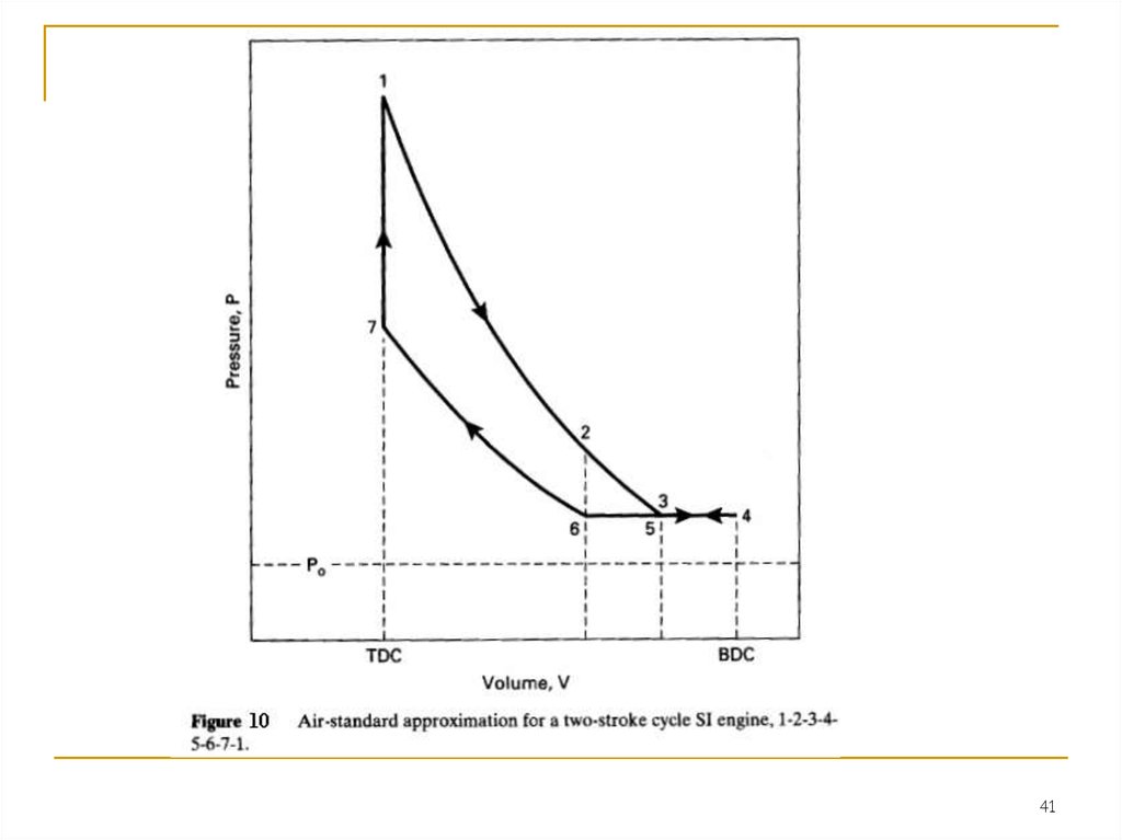
40. TWO-STROKE CYCLE
4041.
4142.
Process 3-4-5-intake, and exhaust scavenging.Exhaust port open and intake port open:
Intake air entering at an absolute pressure on the order of 140-180
kPa fills and scavenges the cylinder. Scavenging is a process in which
the air pushes out most of the remaining exhaust residual from the
previous cycle through the open exhaust port into the exhaust system,
which is at about one atmosphere pressure. The piston uncovers the
intake port at point 3, reaches BDC at point 4, reverses direction, and
again closes the intake port at point 5. In some engines fuel is mixed
with the incoming air. In other engines the fuel is injected later, after the
exhaust port is closed.
Process 5-6- exhaust scavenging.
Exhaust port open and intake port closed:
Exhaust scavenging continues until the exhaust port is closed at point 6.
42
43.
4344. TWO-STROKE CI ENGINE CYCLE
Many compression ignition engines-especially large ones-operateon two-stroke cycles. These cycles can be approximated by the airstandard cycle shown in Fig. 11. This cycle is the same as the twostroke SI cycle except for the fuel input and combustion process.
Instead of adding fuel to the intake air or early in the compression
process, fuel is added with injectors late in the compression process,
the same as with four-stroke cycle CI engines. Heat input or
combustion can be approximated by a two-step (dual) process .
44
45.
4546.
4647. SUMMARY
This chapter reviewed the basic cycles used in internal combustionengines. Although many engine cycles have been developed, for over a
century most automobile engines have operated on the basic SI four-stroke
cycle developed in the 1870s by Otto and others. This can be approximated
and analyzed using the ideal air-standard Otto cycle. Many small SI engines
operate on a two-stroke cycle, sometimes (erroneously) called a two-stroke
Otto cycle. Early four-stroke CI engines operated on a cycle that can be
approximated by the air-standard Diesel cycle. This cycle was improved in
modern CI engines of the type used in automobiles and trucks.
Most small CI engines and very large CI engines operate on a two-stroke
cycle. At present, most automobile engines operate on the four-stroke Otto
cycle, but major research and development is resulting in two additional cycles
for modem vehicles. Several companies have done major development work
to try to create an automobile engine that would operate on an SI two-stroke
cycle. Throughout history, two-stroke cycle automobile engines have
periodically appeared with varying success. These offer greater power per unit
weight, but none would pass modem emission standards. Recent development
has concentrated on producing an engine that would satisfy pollution laws.
The major technological change is the input of fuel by injection directly into the
combustion chamber after exhaust and air intake are completed. If this
development work is successful, there will be automobiles on the market with
two-stroke cycle engines.
47