


 physics
Similar presentations:


")

Compass - magnetic and gyro
1.
2.
COMPASSESDeviation of Magnetic
Compasses
© STC AVANT 2015
PREPARED BY CAPT Y. BYCHKOVKSIY
3.
COMPASSESSTCW – 78, as amended
Requirements, stated in Tables A-II/1, A-II/2 :
“ .... Compass - magnetic and gyro …..”
Knowledge of the principles of magnetic and gyro compasses.
Ability to determine errors of the magnetic and gyro
compasses, using celestial and terrestrial means, and to allow
for such errors.”
© STC AVANT 2015
PREPARED BY CAPT Y. BYCHKOVKSIY
4.
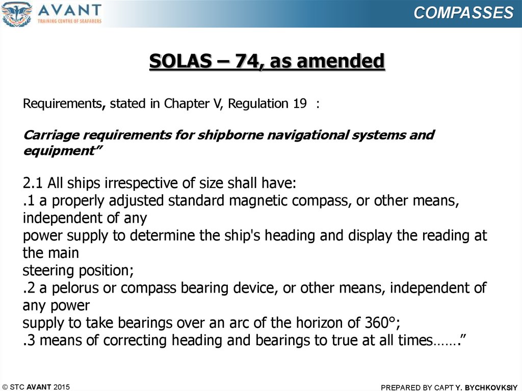
COMPASSESSOLAS – 74, as amended
Requirements, stated in Chapter V, Regulation 19 :
Carriage requirements for shipborne navigational systems and
equipment”
2.1 All ships irrespective of size shall have:
.1 a properly adjusted standard magnetic compass, or other means,
independent of any
power supply to determine the ship's heading and display the reading at
the main
steering position;
.2 a pelorus or compass bearing device, or other means, independent of
any power
supply to take bearings over an arc of the horizon of 360°;
.3 means of correcting heading and bearings to true at all times…….”
© STC AVANT 2015
PREPARED BY CAPT Y. BYCHKOVKSIY
5.
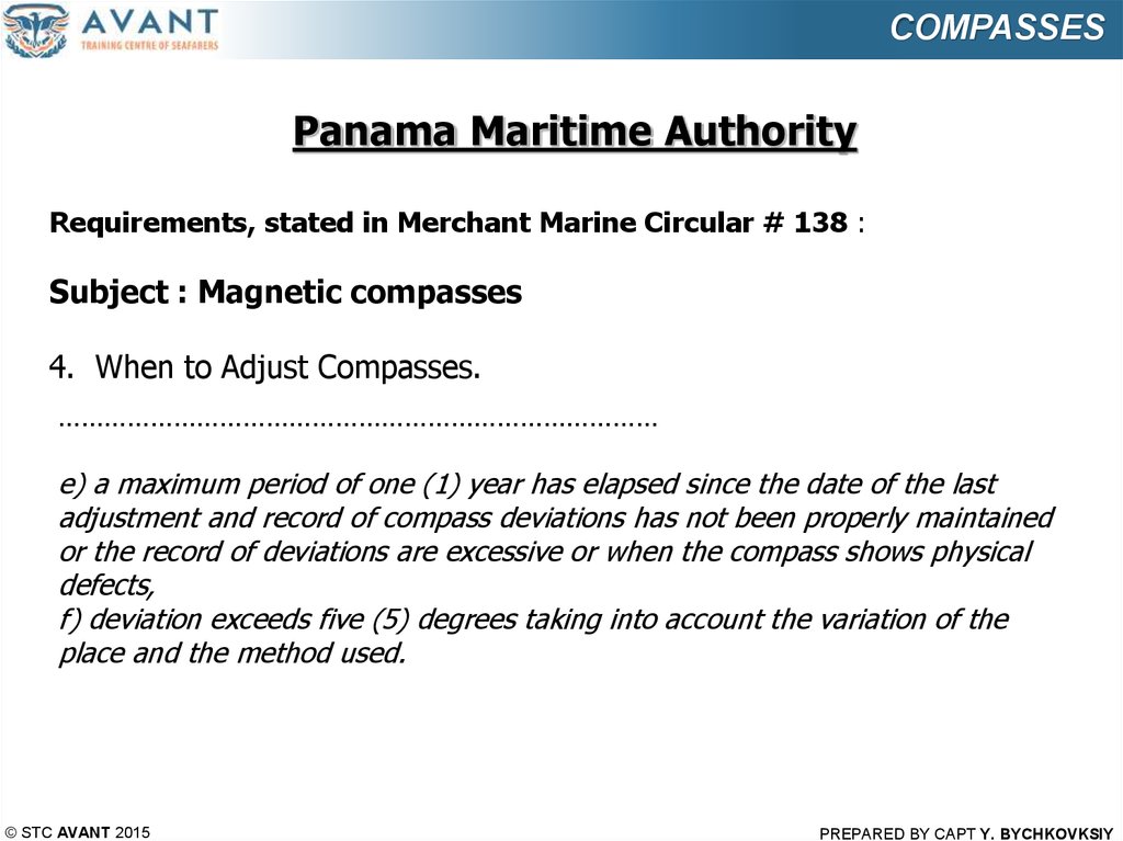
COMPASSESPanama Maritime Authority
Requirements, stated in Merchant Marine Circular # 138 :
Subject : Magnetic compasses
4. When to Adjust Compasses.
……………………………………………………………………
e) a maximum period of one (1) year has elapsed since the date of the last
adjustment and record of compass deviations has not been properly maintained
or the record of deviations are excessive or when the compass shows physical
defects,
f) deviation exceeds five (5) degrees taking into account the variation of the
place and the method used.
© STC AVANT 2015
PREPARED BY CAPT Y. BYCHKOVKSIY
6.
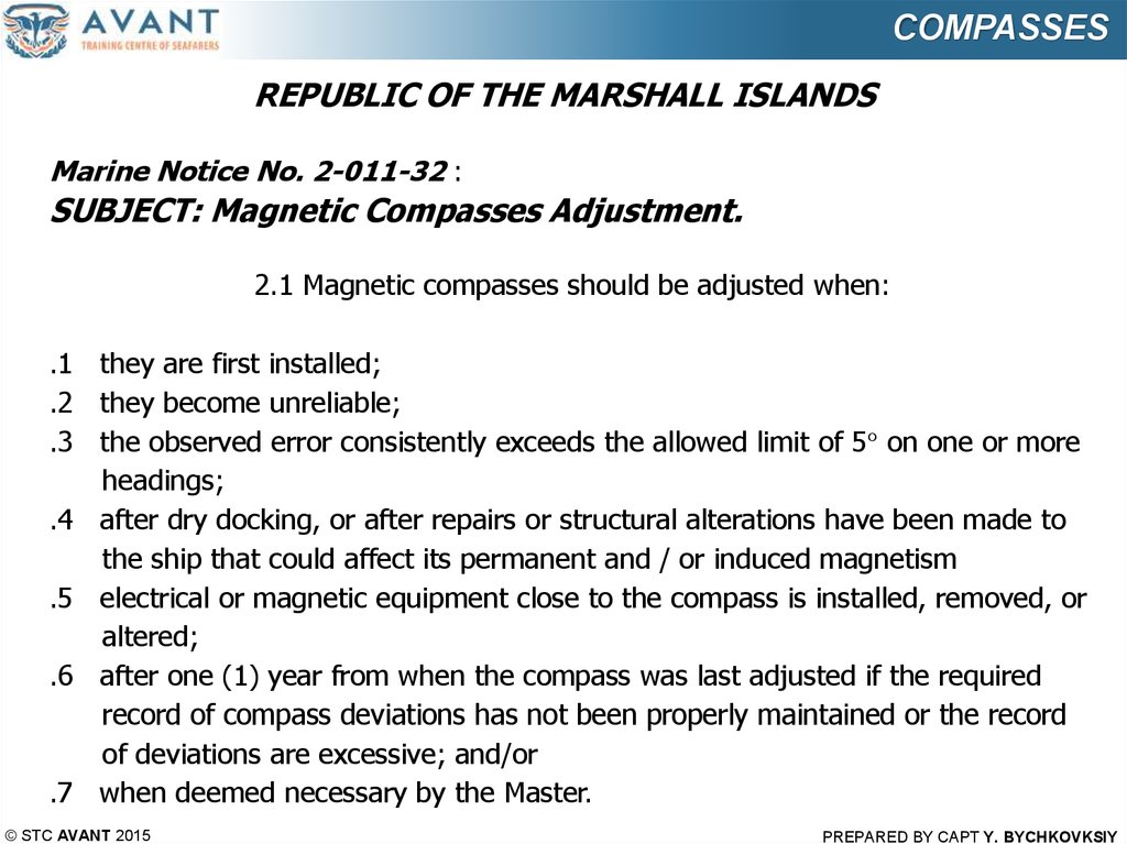
COMPASSESREPUBLIC OF THE MARSHALL ISLANDS
Marine Notice No. 2-011-32 :
SUBJECT: Magnetic Compasses Adjustment.
2.1 Magnetic compasses should be adjusted when:
.1 they are first installed;
.2 they become unreliable;
.3 the observed error consistently exceeds the allowed limit of 5° on one or more
headings;
.4 after dry docking, or after repairs or structural alterations have been made to
the ship that could affect its permanent and / or induced magnetism
.5 electrical or magnetic equipment close to the compass is installed, removed, or
altered;
.6 after one (1) year from when the compass was last adjusted if the required
record of compass deviations has not been properly maintained or the record
of deviations are excessive; and/or
.7 when deemed necessary by the Master.
© STC AVANT 2015
PREPARED BY CAPT Y. BYCHKOVKSIY
7.
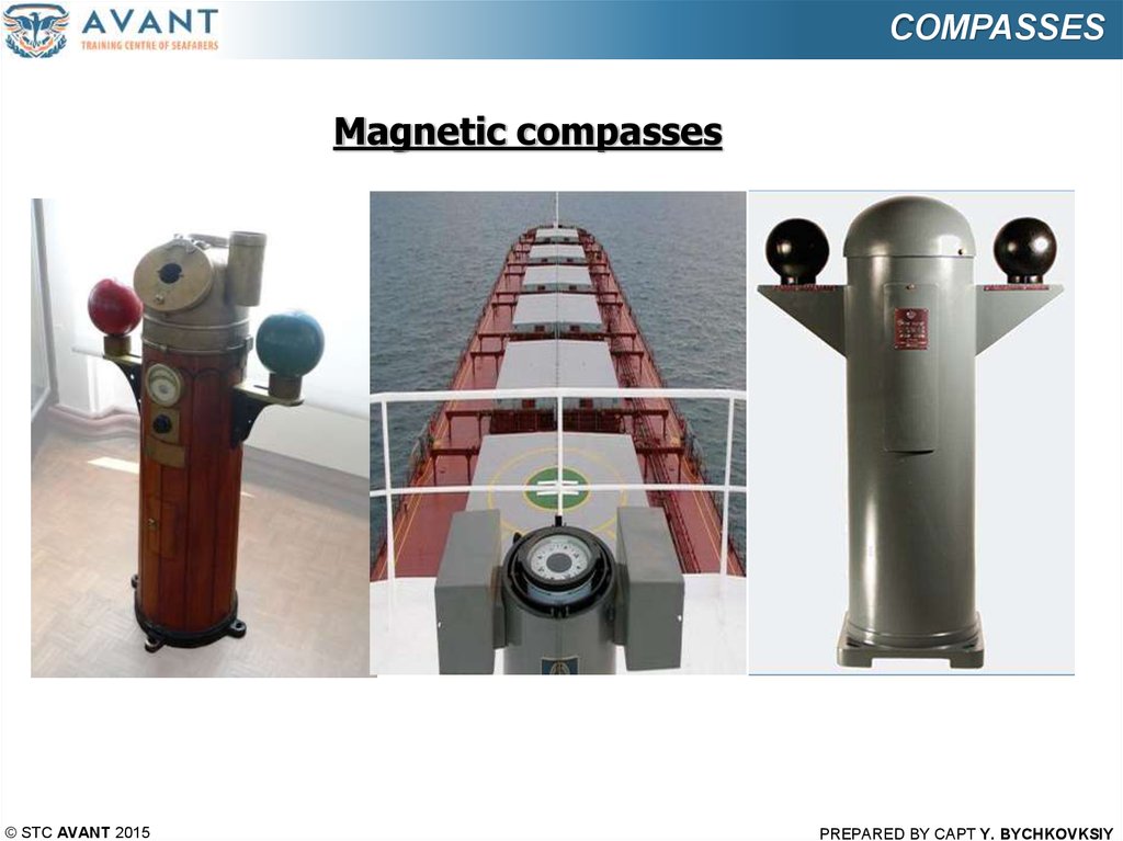
COMPASSESMagnetic compasses
© STC AVANT 2015
PREPARED BY CAPT Y. BYCHKOVKSIY
8.
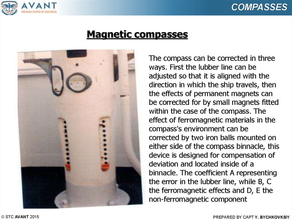
COMPASSESMagnetic compasses
The compass can be corrected in three
ways. First the lubber line can be
adjusted so that it is aligned with the
direction in which the ship travels, then
the effects of permanent magnets can
be corrected for by small magnets fitted
within the case of the compass. The
effect of ferromagnetic materials in the
compass's environment can be
corrected by two iron balls mounted on
either side of the compass binnacle, this
device is designed for compensation of
deviation and located inside of a
binnacle. The coefficient A representing
the error in the lubber line, while B, C
the ferromagnetic effects and D, E the
non-ferromagnetic component
© STC AVANT 2015
PREPARED BY CAPT Y. BYCHKOVKSIY
9.
COMPASSESMagnetic compasses
A ship under construction or repair will acquire permanent magnetism due to
hammering and vibration while sitting stationary in the Earth’s magnetic field.
In addition to its permanent magnetism, a ship acquires induced magnetism
when placed in the Earth’s magnetic field. The magnetism induced in any given
piece of soft iron is a function of the field intensity, the alignment of the soft iron
in that field, and the physical properties and dimensions of the iron. This
induced magnetism may add to, or subtract from, the permanent magnetism
already present in the ship, depending on how the ship is aligned in the
magnetic field.
The magnetism in the various structures of a ship, which tends to change as a
result of cruising, vibration, or aging, but which does not alter immediately so as
to be properly termed induced magnetism, is called subpermanent
magnetism.
© STC AVANT 2015
PREPARED BY CAPT Y. BYCHKOVKSIY
10.
COMPASSESMain Reasons of Compasses Deviation
1.
2.
3.
4.
5.
6.
7.
8.
9.
10.
11.
12.
13.
14.
15.
© STC AVANT 2015
magnetic cargo
hoisting booms
cable reels
metal doors in wheelhouse
knives or tools near binnacle
electric motors
magnetic controllers
gyro repeaters
loudspeakers
electric indicators
electric welding
large power circuits (magnetic grabs)
searchlights or flashlights
electrical control panels or switches
minesweeping power circuits
PREPARED BY CAPT Y. BYCHKOVKSIY
11.
COMPASSESTypes of deviation
1. Round deviation
2. Semicircular deviation
3. Quandrantal deviation
Coefficients of deviation
Coefficient “A” Coefficient “A” represents a deviation of the same name
and amount on all courses. It is really an index error, due usually to a
mechanical defect in the compass, such as the magnetic axis of the needles
not being parallel to a line drawn through the north and south points of the
card, or the card itself not being accurately centred and graduated, the
lubber line misplaced, or an error in computing the magnetic bearing of the
distant object by which the compass was adjusted.
The value of A is the mean of the deviation on the cardinal and intercardinal points, and takes the name of the greater, + A when Est, — A when
Wst. In good compasses it is small in amount and causes no practical
inconvenience.
© STC AVANT 2015
PREPARED BY CAPT Y. BYCHKOVKSIY
12.
COMPASSESCoefficients of deviation
Coefficient “B” Coefficient “B” is the fore and aft component of semicircular deviation, caused by sub-permanent magnetism.
The deviation is greatest when the ship's head is Est and Wst, magnetic,
decreasing to zero on the Nth and Sth points.
+ “B” represents an attraction to the bow.
- “B” an attraction to the stern.
+ “B” gives Est deviation on easterly courses and Wst deviation on westerly
courses.
- “B” gives deviation of an opposite name.
This fore and aft force is compensated by placing a magnet fore and aft with
its north end aft for – “B”, but its north end forward for +”B”, and moving
the magnet towards the compass until the needle points north magnetic, the
ship’s head being steadied temporarily for the purpose on east magnetic or
west magnetic, the maximum deviation then produced being a measure of
the intensity of the horizontal component of the ship’s magnetism acting in
the fore and aft vertical plane passing through the compass.
Deviation = “B” x sin CC
© STC AVANT 2015
PREPARED BY CAPT Y. BYCHKOVKSIY
13.
COMPASSESCoefficients of deviation
Coefficient “C” This is all represented by the athwartshaip component of
semi-circular deviation due to sub-permanent magnetism, the deviation
being greatest when the ship’s head is N. and S. magnetic, decreasing to
zero on the E. and W. points.
+C represents an attraction to starboard.
- C to port.
+ C gives E. dev. on northerly courses and W. dev. on southerly courses.
- C gives deviations of an opposite name.
This athwartship force is compensated by a magnet placed athwartships
with its north end to starboard for +C but to port for - C, and moving the
magnet towards the compass until the needle points north magnetic, the
ship’s head being steadied temporarily on north or south magnetic as the
maximum deviation then produced is a measure of the intensity of the ship’s
magnetism in the athwartship vertical plane passing through the compass.
Deviation = “C” x cos CC
© STC AVANT 2015
PREPARED BY CAPT Y. BYCHKOVKSIY
14.
COMPASSESCoefficients of deviation
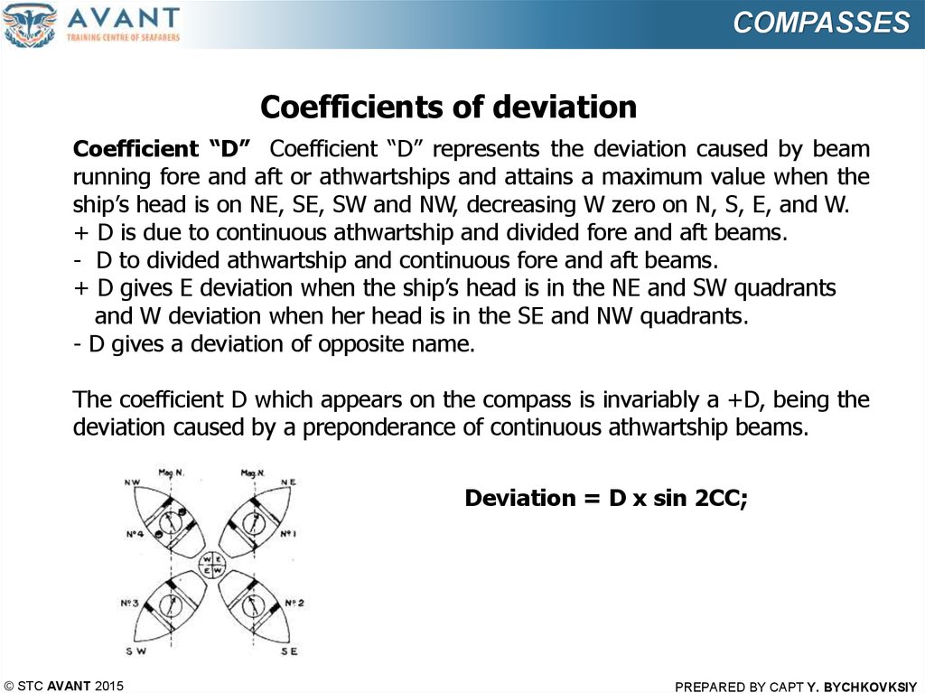
Coefficient “D” Coefficient “D” represents the deviation caused by beam
running fore and aft or athwartships and attains a maximum value when the
ship’s head is on NE, SE, SW and NW, decreasing W zero on N, S, E, and W.
+ D is due to continuous athwartship and divided fore and aft beams.
- D to divided athwartship and continuous fore and aft beams.
+ D gives E deviation when the ship’s head is in the NE and SW quadrants
and W deviation when her head is in the SE and NW quadrants.
- D gives a deviation of opposite name.
The coefficient D which appears on the compass is invariably a +D, being the
deviation caused by a preponderance of continuous athwartship beams.
Deviation = D x sin 2CC;
© STC AVANT 2015
PREPARED BY CAPT Y. BYCHKOVKSIY
15.
COMPASSESCoefficients of deviation
Coefficient “E” Coefficient “E” represents the deviation caused by
diagonal beams which cross the deck at an angle of 45°. It attains a
maximum value when the ship’s head is on N, E, S, and W, decreasing
zero on NE, SE, SW, and NW
+ “E” is due to beams extending continuously from the port bow to the
starboard quarter; and
- “E” when they extend from the starboard bow to the port quarter.
Deviation = “E” x cos 2CC;
The quadrantal deviation is due to soft horizontal iron
and the correction is made by means of soft horizontal
iron, it follows, therefore, that when the compensation is
properly made it should remain so for all latitudes,
because the ratio between the disturbing and the
correcting forces remains the same, provided the spheres
are not close enough to the compass to become magnet
used by induction from the needles.
© STC AVANT 2015
PREPARED BY CAPT Y. BYCHKOVKSIY
16.
COMPASSESCompensation of deviation
• if there is a sea running, steer
course 000° and adjust the
heeling magnet to decrease
oscillations to a minimum;
• come to course 090°; when
steady on course 090°, for at
least two minutes, insert,
remove, or move fore-and-aft
“B” magnets to remove ALL
deviation;
• come to a heading of 180°;
insert, remove, or move
athwartships “C” magnets to
remove ALL deviation;
© STC AVANT 2015
PREPARED BY CAPT Y. BYCHKOVKSIY
17.
COMPASSESCompensation of deviation
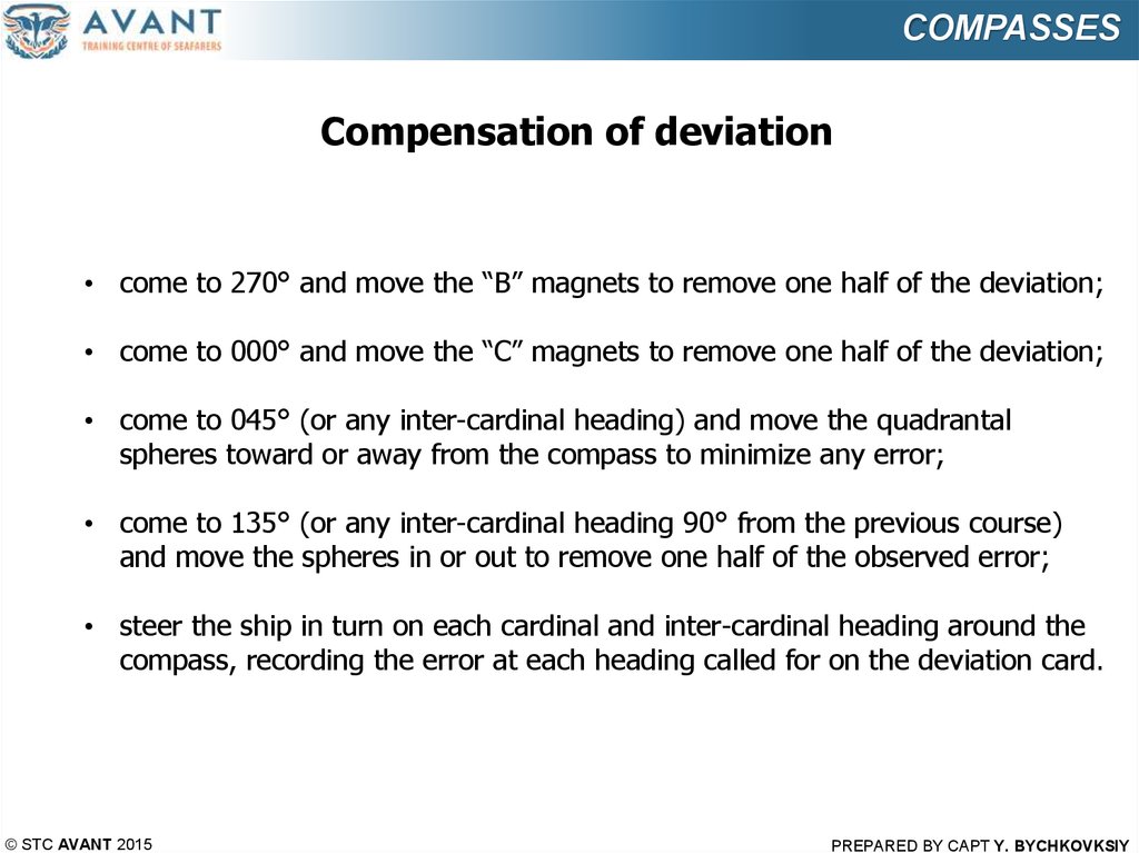
• come to 270° and move the “B” magnets to remove one half of the deviation;
• come to 000° and move the “C” magnets to remove one half of the deviation;
• come to 045° (or any inter-cardinal heading) and move the quadrantal
spheres toward or away from the compass to minimize any error;
• come to 135° (or any inter-cardinal heading 90° from the previous course)
and move the spheres in or out to remove one half of the observed error;
• steer the ship in turn on each cardinal and inter-cardinal heading around the
compass, recording the error at each heading called for on the deviation card.
© STC AVANT 2015
PREPARED BY CAPT Y. BYCHKOVKSIY
18.
COMPASSESCompensation by the method of “Airy”
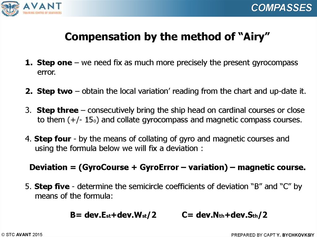
1. Step one – we need fix as much more precisely the present gyrocompass
error.
2. Step two – obtain the local variation’ reading from the chart and up-date it.
3. Step three – consecutively bring the ship head on cardinal courses or close
to them (+/- 15o) and collate gyrocompass and magnetic compass courses.
4. Step four - by the means of collating of gyro and magnetic courses and
using the formula below we will fix a deviation :
Deviation = (GyroCourse + GyroError – variation) – magnetic course.
5. Step five - determine the semicircle coefficients of deviation “B” and “C” by
means of the formula:
B= dev.Est+dev.Wst/2
© STC AVANT 2015
C= dev.Nth+dev.Sth/2
PREPARED BY CAPT Y. BYCHKOVKSIY
19.
COMPASSESCompensation by the method of “Airy”
6. Step six - after berthing and having a stabile magnetic condition of
the ship we will calculate the deviation’ value on the magnetic course
alongside a dock by the formula :
Deviation ”B”= B x sin C ;
Deviation “C”= C x cos C.
7. Step seven - having the calculated values of deviation B & C, we will
open a deviation’ compensation device inside a binnacle and will
commence a whole procedure of semicircle deviation’ compensation.
8. Step eight – by means of longitudinal and athwartship magnets we
will compensate a semicircular deviation by the simplest moving of the
magnets up and down the slops or rotating an appropriate compensation
knob. The special attention to be paid to the polarity of coefficients “B”
and “C”.
© STC AVANT 2015
PREPARED BY CAPT Y. BYCHKOVKSIY
20.
COMPASSESCompensation by the method of “Airy”
9. Step nine – on completion of compensation we shall determine the residual
values of deviation (coefficients “B” and “C”). Having in mind that coefficient
“A” and quadrantal coefficient “D” and “E” are subjects of a small changes
during a voyage, we can assume that they are permanent and calculate
their
values based on the previous deviation’ table readings and issue a new
deviation table.
10. Step ten – compensation of semicircle, quadrantal, Flinders and heeling
deviation.
It is important to understand what to do on completion of deviation’
determine, because a wrong inserting of a magnet could make a whole
picture much worse, as it being before. For this reason, Tables
1,2,3,4,5,6 are attached.
© STC AVANT 2015
PREPARED BY CAPT Y. BYCHKOVKSIY
21.
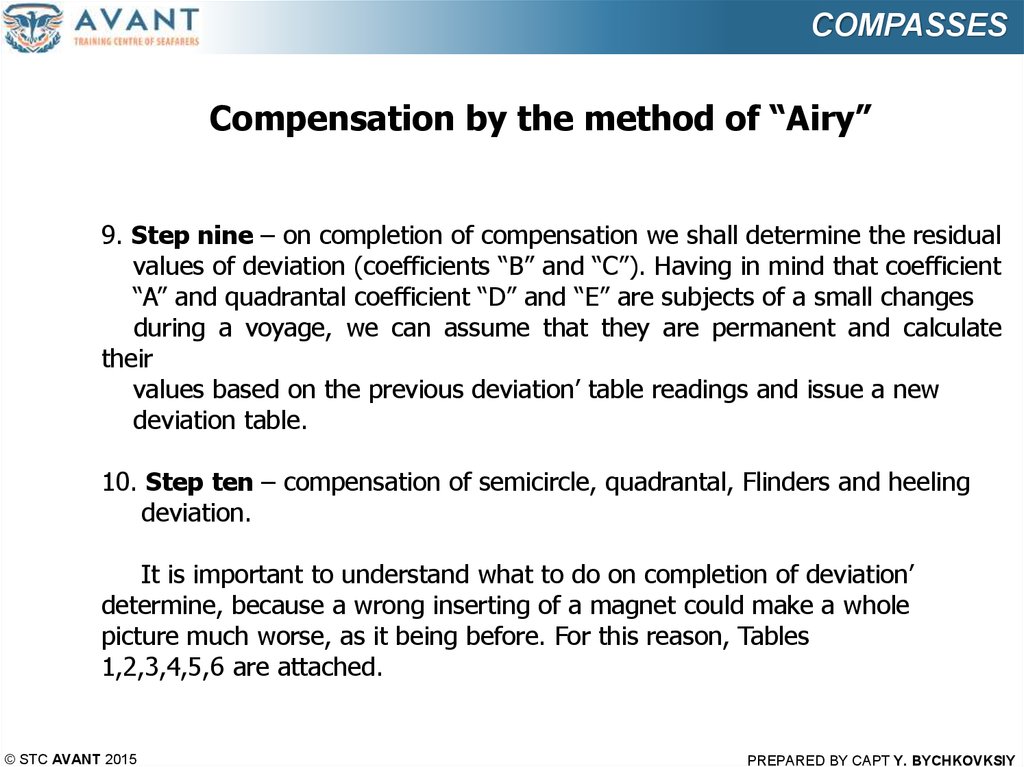
COMPASSESCompensation’ tables for coefficients “B” & “C”
Table 1 coefficient “B”
© STC AVANT 2015
Table 2 coefficient “C”
PREPARED BY CAPT Y. BYCHKOVKSIY
22.
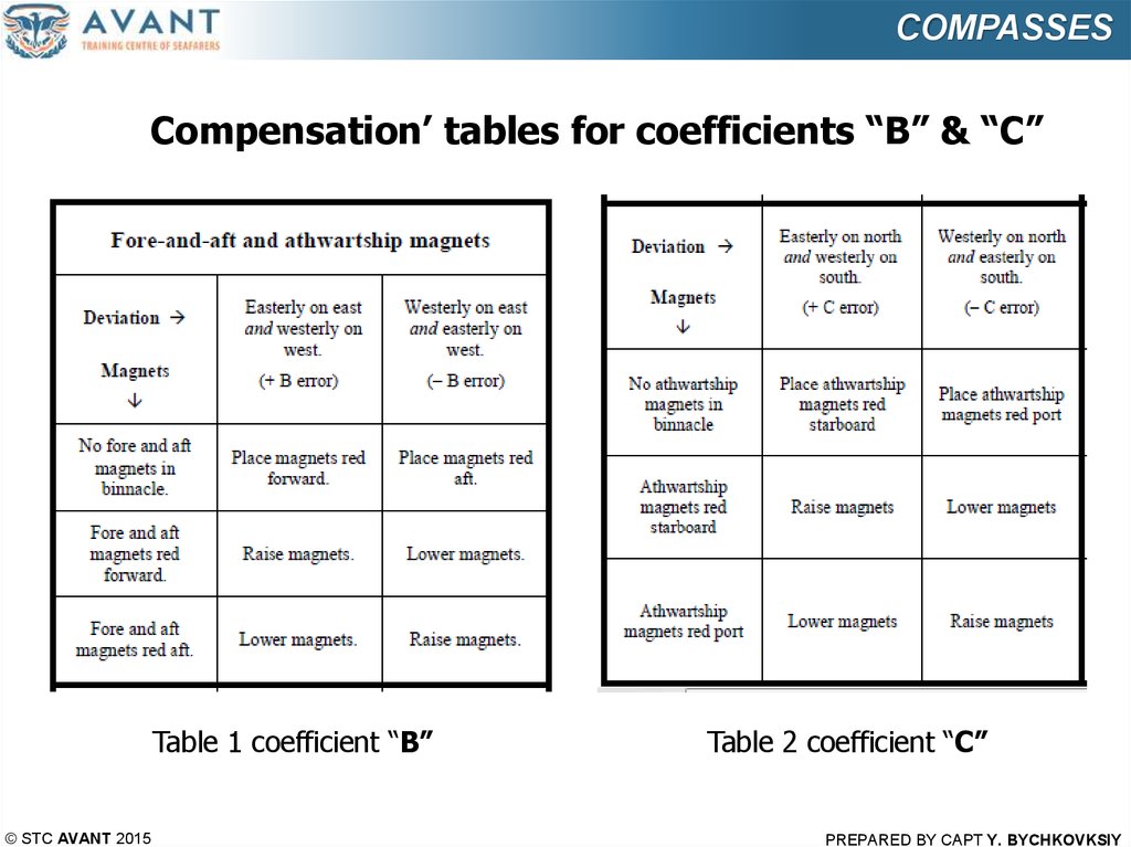
COMPASSESCompensation’ tables for coefficients “D” & “E”
Table 3 coefficient “D”
© STC AVANT 2015
Table 4 coefficient “E”
PREPARED BY CAPT Y. BYCHKOVKSIY
23.
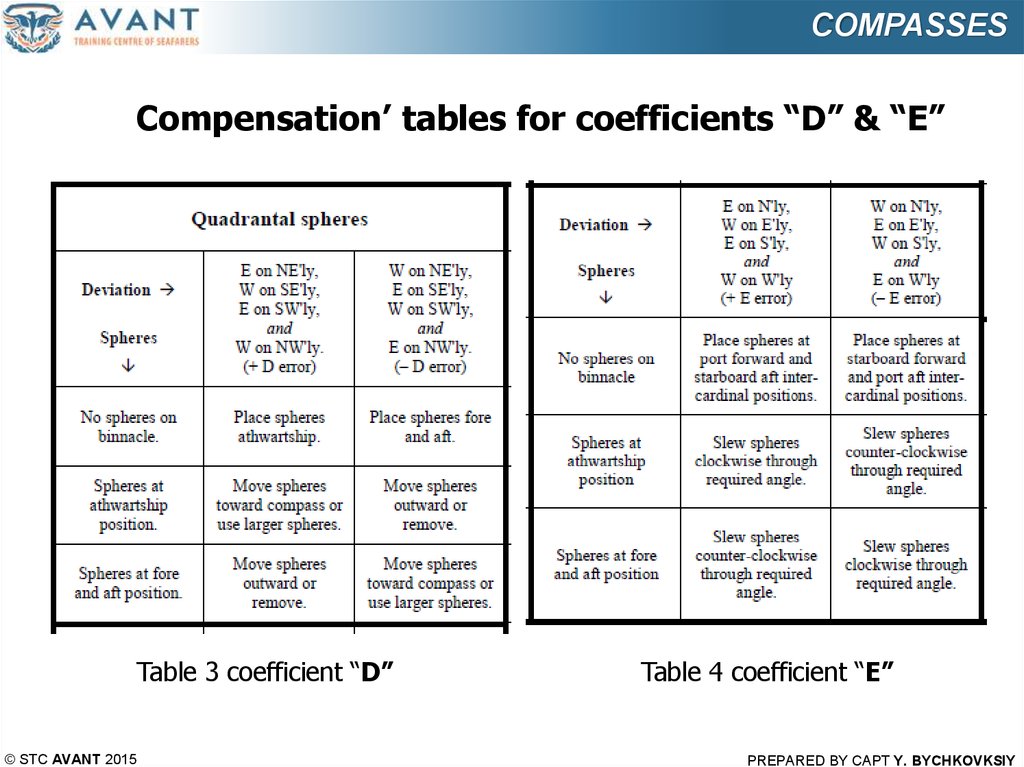
COMPASSESCompensation’ tables Flinders bar & Heeling magnet
Table 5 Flinders bar & Heeling magnet
© STC AVANT 2015
PREPARED BY CAPT Y. BYCHKOVKSIY
24.
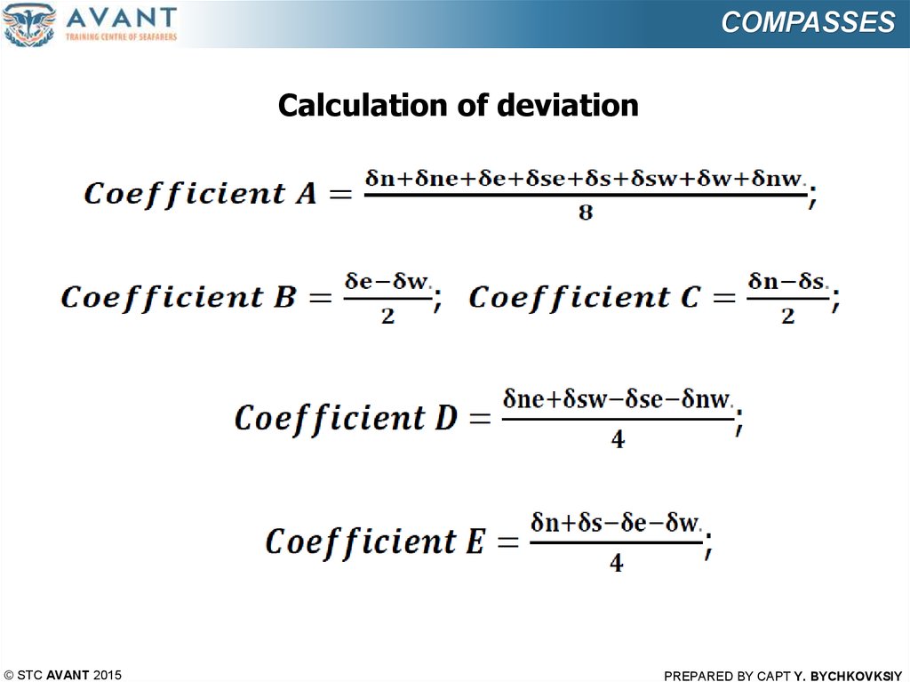
COMPASSESCalculation of deviation
© STC AVANT 2015
PREPARED BY CAPT Y. BYCHKOVKSIY
25.
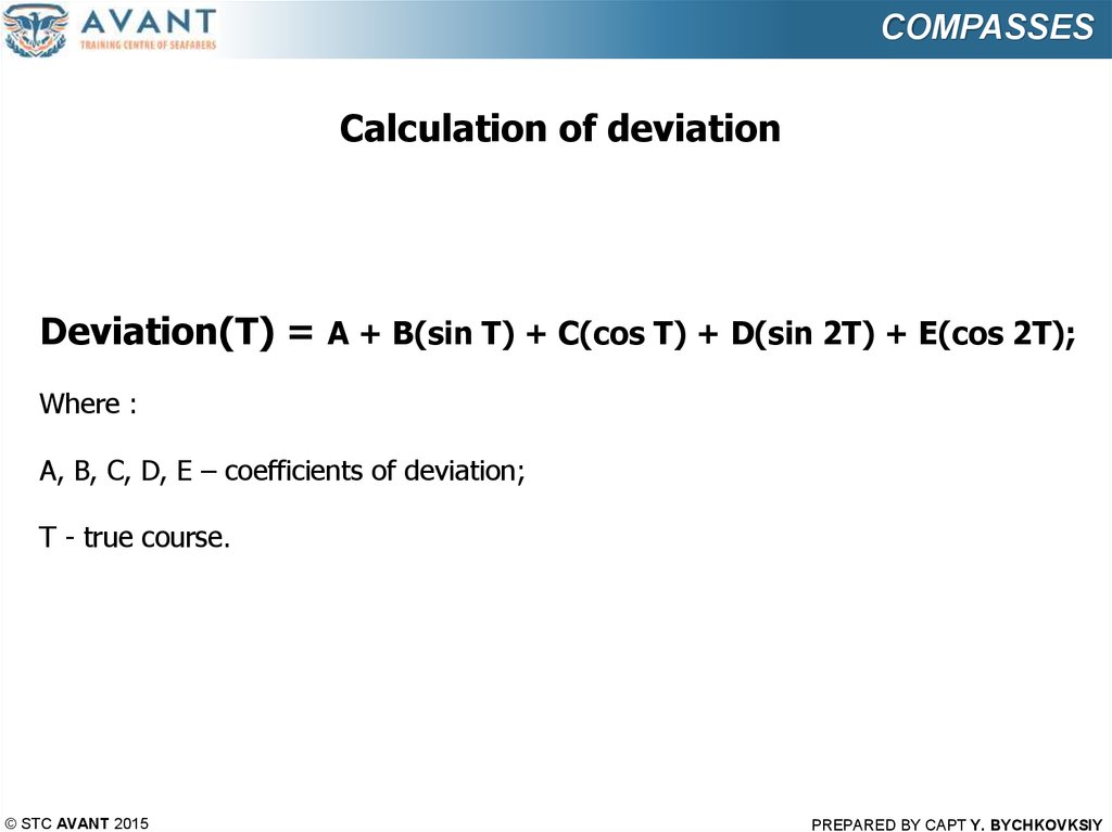
COMPASSESCalculation of deviation
Deviation(T) = A + B(sin T) + C(cos T) + D(sin 2T) + E(cos 2T);
Where :
A, B, C, D, E – coefficients of deviation;
T - true course.
© STC AVANT 2015
PREPARED BY CAPT Y. BYCHKOVKSIY