


")
")


")


 with telegraph")
 Without telegraph")


 electronics
Similar presentations:

")


")


MAN B&W Diesel
1.
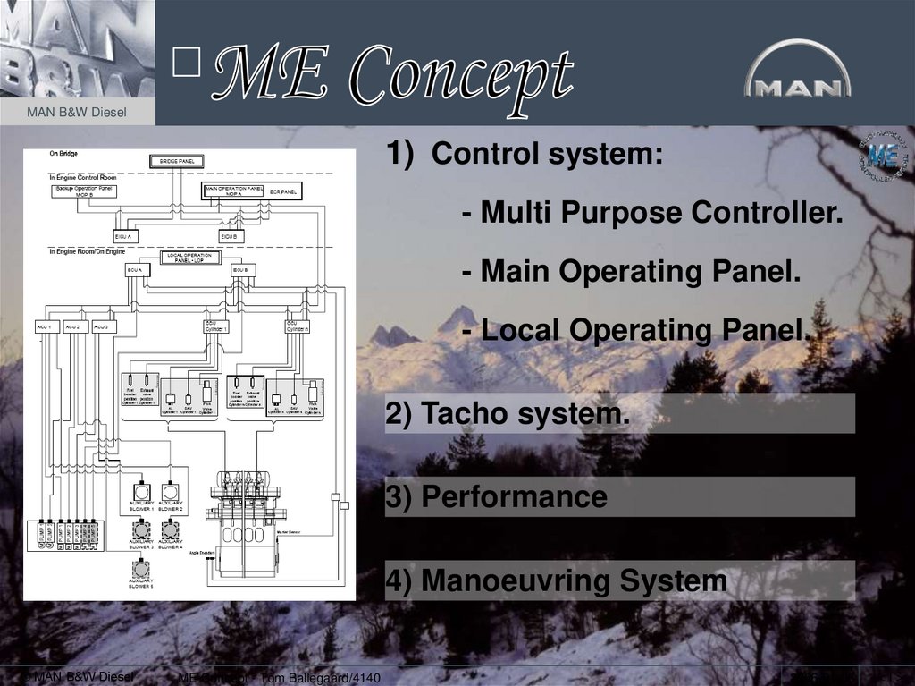
MAN B&W Diesel1) Control system:
- Multi Purpose Controller.
- Main Operating Panel.
- Local Operating Panel.
2) Tacho system.
3) Performance
4) Manoeuvring System
© MAN B&W Diesel
ME Concept - Tom Ballegaard/4140
2006-01-06
<1>
2. ME engine Hydraulic Loop
MAN B&W DieselFuel oil pressure
Exhaust valve actuator
booster
Hydraulic
cylinder unit
Fuel 10 bar
ELFI
ELVA
200 bar
Alpha lubricator
Cyl. 1 CCU Cyl. 2 CCU Cyl. 3 CCU
Cyl. 4 CCU
Cyl. 5 CCU Cyl. 6 CCU
Safety and
Accumulator
blok
Fine aut. filter
Main lube
pump
Piston cooling
+ bearings
Servo oil
Servo oil
return to sump
From sump
Engine driven
hydraulic pumps
© MAN B&W Diesel
L/73273-7.1/0403
(2600/RØL)
EL. driven
hydraulic pumps
<2>
3. Engine Control System MPC & Network
Engine Control SystemMPC & Network
MAN B&W Diesel
• The Multi Purpose Controllers are
identical hardware wise.
• They have different soft ware
configurations.
• 2 redundant control networks are
connecting all Multi Purpose Controllers
and both Main Operating Panels.
• A backup of the application- and
setup- soft ware are stored on both
Main Operation Panels.
• At replacement, the new controller
are automatically configured with
correct soft ware via the control
networks.
© MAN B&W Diesel
ME Concept - Tom Ballegaard/4140
2006-01-06
<3>
4. Multi Purpose Controller - MPC
MAN B&W DieselBattery for internal clock
LED indicator
Plug for ID key
DIP Switches
Fuses in use are monitored by the alarm system
© MAN B&W Diesel
ME Concept - Tom Ballegaard/4140
Power plug
2006-01-06
<4>
5. LED information Code
MAN B&W DieselThe LED gives information, either as constant light of flashing.
A flashing LED is a coded message from the controller.The code consists of 2 digits:
1. digit are given by red flashes on yellow background
2. digit are given by green flashes on yellow background
The 2 digits are seperated by a 1 sec. yellow pulse.
© MAN B&W Diesel
ME Concept - Tom Ballegaard/4140
2006-01-06
<5>
6. LED indication code
MAN B&W Diesel© MAN B&W Diesel
ME Concept - Tom Ballegaard/4140
2006-01-06
<6>
7. Multi Purpose Controller (MPC)
MAN B&W Diesel© MAN B&W Diesel
ME Concept - Tom Ballegaard/4140
2006-01-06
<7>
8. Multi Purpose Controller (MPC)
MAN B&W DieselMulti Purpose Controller
Supporting bracket for cables
Amplifier
© MAN B&W Diesel
ME Concept - Tom Ballegaard/4140
2006-01-06
<8>
9. MPC’s Nordic Brasilia – 6S70ME-C
MAN B&W Diesel© MAN B&W Diesel
ME Concept - Tom Ballegaard/4140
2006-01-06
<9>
10. MPC – configuration
MAN B&W DieselThe MPC’s are software wise configured to
4 different controller functions:
1) Engine Interface Conrol Unit – EICU
• 2 complete redundant units
• Handles the interface to external systems
2) Engine Control Unit – ECU
• 2 complete redundant units (except with 4 or more engine driven pumps)
• Handles the engine specific control functions (the govenor)
3) Cylinder Control Unit – CCU
• 1 for each cylinder unit, redundancy by multiplicity
• Handles the cylinder specific functions (fuel injection, exh. Valve, cylinder lubrication and
starting air valves)
4) Auxilliary Control Unit – ACU
• 3 units, redundancy by multiplicity
• Handles the auxilliary systems (hydraulic power supply, aux blowers)
© MAN B&W Diesel
ME Concept - Tom Ballegaard/4140
2006-01-06
< 10 >
11. Engine Interface Control Unit – EICU
MAN B&W DieselInterface to remote control systems:
• Safety system
• Alarm system
• Telegraph system
• Power management system
Operator inputs:
• Control station selection - Bridge, Engine control room or Local control
• Standby / Finished with engine
Speed set point – Filter between handle and govenor:
• Slow down
• Shaft generator
• Controlling accelaration
• Load control
• Barred speed range
© MAN B&W Diesel
ME Concept - Tom Ballegaard/4140
2006-01-06
< 11 >
12. Speed Setpoint
MAN B&W Diesel© MAN B&W Diesel
ME Concept - Tom Ballegaard/4140
2006-01-06
< 12 >
13. Engine Control Unit – ECU
MAN B&W DieselStart / stop logic
• Prepare start (MOP or handle)
• Repeated start, (total 3 attempts, reset by setting the handle in ’STOP’)
• Start blocking
• Slow turning
• Manual air run
Engine speed control and limiters
• Calculations of fuel index
• Limiters (start, max fuel all and individual, torque, scav.air, hydraulic press.)
• Feed forward (pitch, PTO power)
Engine running mode control
• Emission mode
• Economy mode
© MAN B&W Diesel
ME Concept - Tom Ballegaard/4140
2006-01-06
< 13 >
14. Fuel Limiters
MAN B&W Diesel© MAN B&W Diesel
ME Concept - Tom Ballegaard/4140
2006-01-06
< 14 >
15. Cylinder Control Unit – CCU
MAN B&W DieselFuel injection control
• Proportional valve
• Feedback of plunger position only used for monitoring
Exhaust valve control
• ON / OFF valve
• Feedback signal for exh. Valve position, used in determination of valve timing
Cylinder lubrication
• ON / OFF valve controling the alpha lubricator
• Feed rate controlled in the ECU
Starting air valve control (timing of solenoid valve)
• ON / OFF valve
© MAN B&W Diesel
ME Concept - Tom Ballegaard/4140
2006-01-06
< 15 >
16. Engine Control System CCU
MAN B&W DieselFiva valve, Fuel & exhaust
Fuel plunger pos. feedback
Exh. Spindle pos. feedback
Cylinder lubrication
Starting air valve
One CCU for every cylinder
unit
© MAN B&W Diesel
ME Concept - Tom Ballegaard/4140
2006-01-06
< 16 >
17. Auxiliary Control Unit - ACU
MAN B&W DieselControl of Hydraulic Power Supply:
• Engine driven pumps
• Start-up pumps
• Valves and pressure gauges
Individual control of aux blower:
• Sequential start by different start delays
• Engine contol blower / stop is decided in ECU
© MAN B&W Diesel
ME Concept - Tom Ballegaard/4140
2006-01-06
< 17 >
18. Engine Control System Auxiliary Blowers
MAN B&W DieselAux blower No. 1 is controlled by ACU 1
Aux blower No. 2 is controlled by ACU 2
Aux blower No. 3 is controlled by ACU 3
Aux blower No. 4 is controlled by ACU 1
Aux blower No. 5 is controlled by ACU 2
© MAN B&W Diesel
ME Concept - Tom Ballegaard/4140
2006-01-06
< 18 >
19. Engine Control System Hydraulic Pumps
MAN B&W DieselEl-pump 1 controlled by ACU 1
El-pump 2 controlled by ACU 2
Eng.driven pump 1 controlled by ACU 1,
- Pressure controlled / follow mode
Eng.driven pump 2 controlled by ACU 2,
- Pressure controlled / follow mode
Eng.driven pump 3 controlled by ACU 3,
- Pressure controlled / follow mode
Eng.driven pump 4 controlled by ECU A,
- On-OFF
Eng.driven pump 5 controlled by ECU B,
- On-OFF
© MAN B&W Diesel
ME Concept - Tom Ballegaard/4140
2006-01-06
< 19 >
20. ME Starting Air System
MAN B&W DieselMC-C design
ME-C design
Pilot air inlet
Blow-off
NC-valves
Connection
for
ECS
Starting air
distributor
Starting valves
© MAN B&W Diesel
Starting valves
< 20 >
21. Starting air- and pilot air valve
Starting airand pilot air valveMAN B&W Diesel
Starting air valve
Pilot air valve
© MAN B&W Diesel
ME Concept - Tom Ballegaard/4140
2006-01-06
< 21 >
22. Engine Control System Control Panels
MAN B&W DieselBridge Control system is
connected to EICU
Engine Control Room Panel is
connected to EICU
Local Operating Panel LOP is
connected to ECU
© MAN B&W Diesel
ME Concept - Tom Ballegaard/4140
2006-01-06
< 22 >
23. Main Operation Panel (MOP)
MAN B&W Diesel© MAN B&W Diesel
ME Concept - Tom Ballegaard/4140
2006-01-06
< 23 >
24. Main Operating Panel MOP
MAN B&W Diesel© MAN B&W Diesel
ME Concept - Tom Ballegaard/4140
2006-01-06
< 24 >
25. Main Operating Panel MOP
MAN B&W Diesel© MAN B&W Diesel
ME Concept - Tom Ballegaard/4140
2006-01-06
< 25 >
26. Local Operating Panel (LOP) with telegraph
MAN B&W Diesel© MAN B&W Diesel
ME Concept - Tom Ballegaard/4140
2006-01-06
< 26 >
27. Local Operating Panel (LOP) Without telegraph
MAN B&W Diesel© MAN B&W Diesel
ME Concept - Tom Ballegaard/4140
2006-01-06
< 27 >
28. Engine Control System Tacho System
MAN B&W DieselThere are 2 redundant tacho systems.
System A
System B
Standard is:
angle encoders with one
reference sensor on the flywheel
(A-system)
Option is sensors at the flywheel
© MAN B&W Diesel
ME Concept - Tom Ballegaard/4140
2006-01-06
< 28 >
29. Tacho system
MAN B&W DieselMMA
Q2A
Q1A
MMB
Q1B
System A (powered from ECU A)
Q2B
MMA = Marker Master A
MSA = Marker Slave A
Q1A = Quadratur 1A
Q2A = Quadratur 2A
MSA
System B (powered from ECU B)
MMB = Marker Master B
MSB = Marker Slave B
Q1B = Quadratur 1B
Q2B = Quadratur 2B
Trigger ring
pos. 1
MSB
Semi-circular
marking ring
pos. 2
© MAN B&W Diesel
ME Concept - Tom Ballegaard/4140
2006-01-06
< 29 >
30. ME Tacho-system
MAN B&W Diesel© MAN B&W Diesel
04-11-2003
2500/KNB
2006-01-06
< 30 >
31. ME Tacho-system
MAN B&W Diesel© MAN B&W Diesel
04-11-2003
2500/KNB
2006-01-06
< 31 >
32. Angle encoder – 12K98ME
MAN B&W Diesel© MAN B&W Diesel
ME Concept - Tom Ballegaard/4140
2006-01-06
< 32 >
33. ME Tacho-system
MAN B&W Diesel• 2 redundant set of sensors.
• Each set measure engine speed
and crankshaft position for
synkronisation of the control
events.
• Each set consist of four sensors.
Two quadrature sensors measure on
a trigger ring with 360 tooth and two
marker sensors measures on one
tooth – a semicircular ring.
Triggersegment with a sine-curved toothprofile The total trigger ring is build by 8
equal segments.
© MAN B&W Diesel
2200/OZS/030212
2006-01-06
< 33 >
34. Tacho sensors Nordic Brasilia – 6S70ME-C
MAN B&W Diesel© MAN B&W Diesel
ME Concept - Tom Ballegaard/4140
2006-01-06
< 34 >
35. Tacho sensors, replacement
MAN B&W DieselSensing distance to the highest point on the trigger / marker ring:
1.0 mm
The highest point is marked [T]
Highest point
© MAN B&W Diesel
ME Concept - Tom Ballegaard/4140
2006-01-06
< 35 >
36. Quadratur sensor
MAN B&W DieselStatus LED
Ahead turning towards the dot
© MAN B&W Diesel
ME Concept - Tom Ballegaard/4140
2006-01-06
< 36 >
37. Performance curves
MAN B&W DieselBy changing the exh. Valve timing, the Pcomp can be
adjusted, and then the Pmax can be kept constant in a
bigger range.
The maximum pressure jump is the same as for MC
engine because the combustion chambers are
identical.
© MAN B&W Diesel
ME Concept - Tom Ballegaard/4140
2006-01-06
< 37 >
38. Exhaust valve timing
MAN B&W DieselExhaust valve movement
80
70
60
Early closing
mm
50
Late closing
40
Early opening
Late opening
30
Reference
20
10
0
90
110
130
150
170
190
210
230
250
270
290
Dg. C. A.
© MAN B&W Diesel
< 38 >
39. Pneumatic system
MAN B&W Diesel2 valves for redundancy
No. 30 connected to ECU A
No. 32 connected to ECU B
© MAN B&W Diesel
ME Concept - Tom Ballegaard/4140
2006-01-06
< 39 >