


 mechanics
Similar presentations:


Chapter 8 Flight Controls and Servo Controls
1.
EC 130 B4Initial Pilot Ground School
Chapter 8
Flight Controls
and Servo Controls
2.
Chapter 8 - Flight Controls and Servo ControlsMain Rotor Controls …………...……………………….…………...….… 8.3
Cyclic Controls ……………………………………………….…………….. 8.5
Lever Support Brackets …………………………………………………… 8.8
Mixing Unit Accessories ……….………………...………………………. 8.10
Collective Twist Grips ……..…………..………………………………….. 8.11
Twist Grip Warning Light ………………....……………………………… 8.16
Collective Controls ………………………………………………………… 8.17
Tail Rotor Controls …………………..…………………………………….. 8.21
Tail Rotor Potentiometer …………………………………………………. 8.24
Servo Controls …………………………...………..……………………….. 8.26
Servo Control Operation …………………..……………………………… 8.28
Limit Caution Light ………..…………………….…………………………. 8.35
Distribution Valve Operation - Seizure Sensing ………………………. 8.36
Servo Caution Light ………………………………………………………… 8.38
Servo Caution Light Summary ……………………………………………. 8.43
Review Questions …………………………………………………………... 8.44
8.2
3.
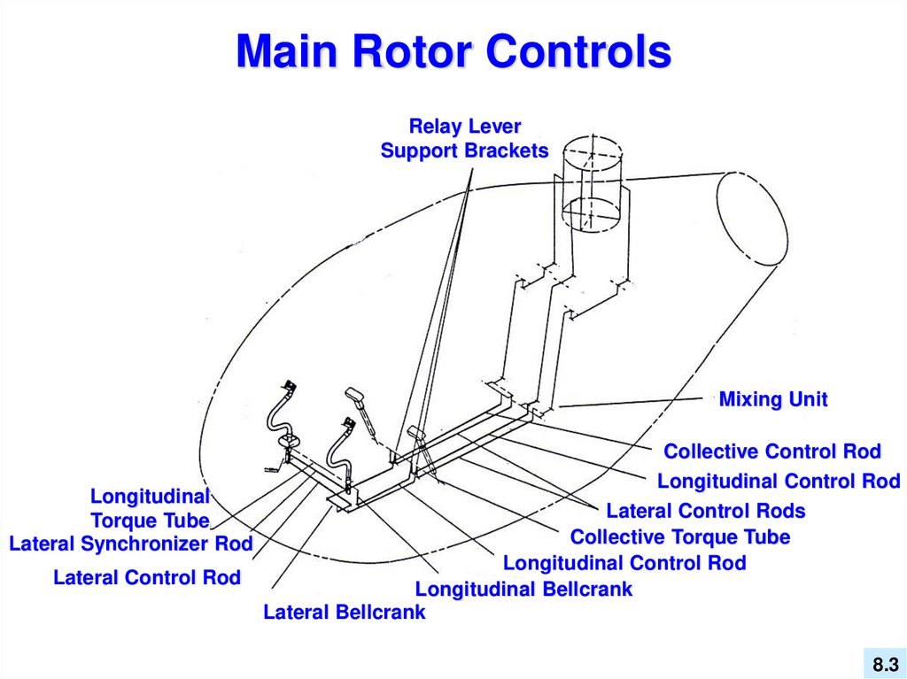
Main Rotor ControlsRelay Lever
Support Brackets
Mixing Unit
Collective Control Rod
Longitudinal Control Rod
Longitudinal
Lateral Control Rods
Torque Tube
Collective Torque Tube
Lateral Synchronizer Rod
Longitudinal Control Rod
Lateral Control Rod
Longitudinal Bellcrank
Lateral Bellcrank
8.3
4.
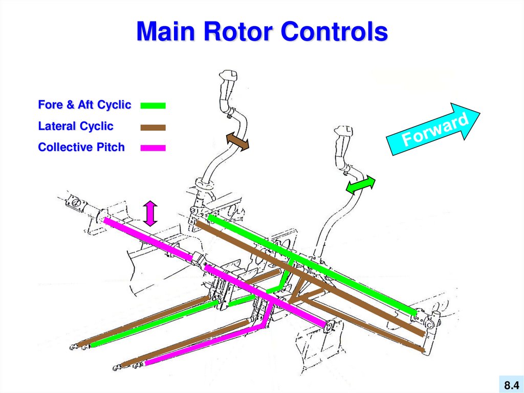
Main Rotor ControlsFore & Aft Cyclic
Lateral Cyclic
Collective Pitch
8.4
5.
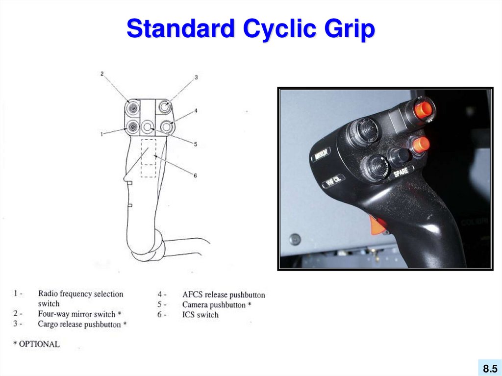
Standard Cyclic Grip8.5
6.
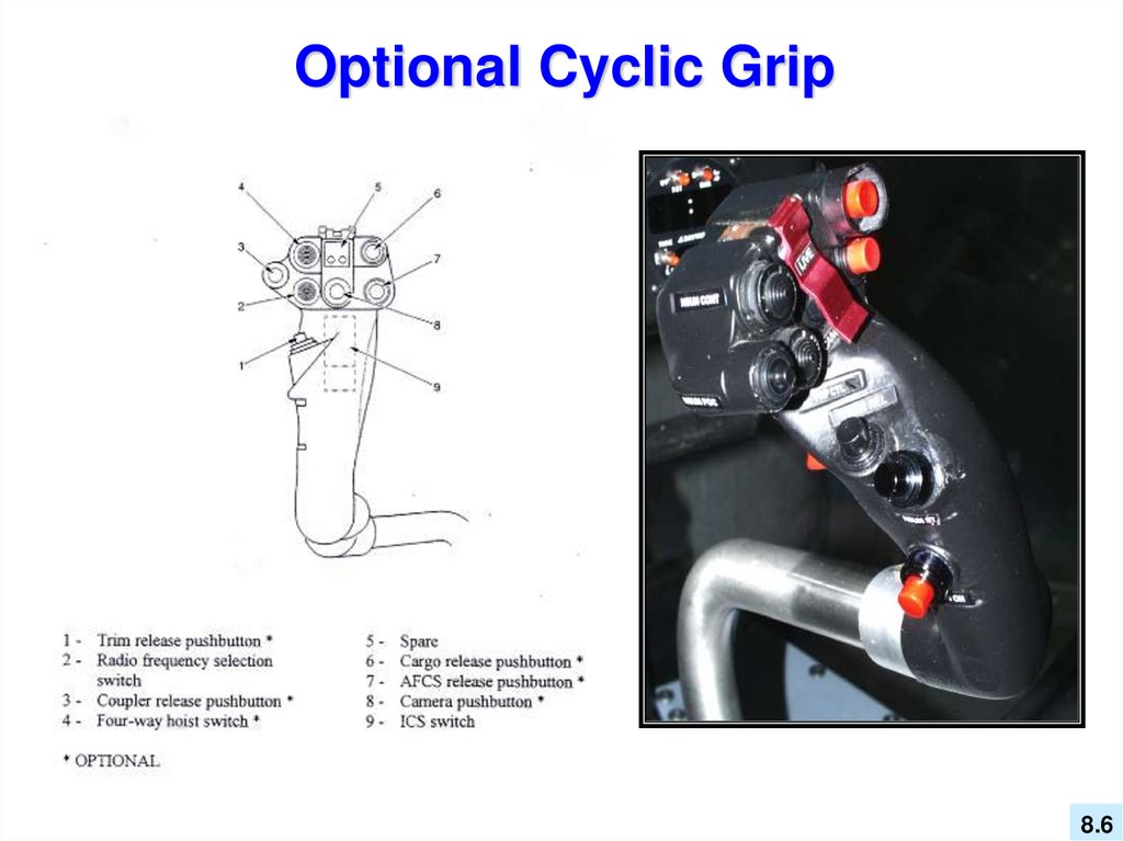
Optional Cyclic Grip8.6
7.
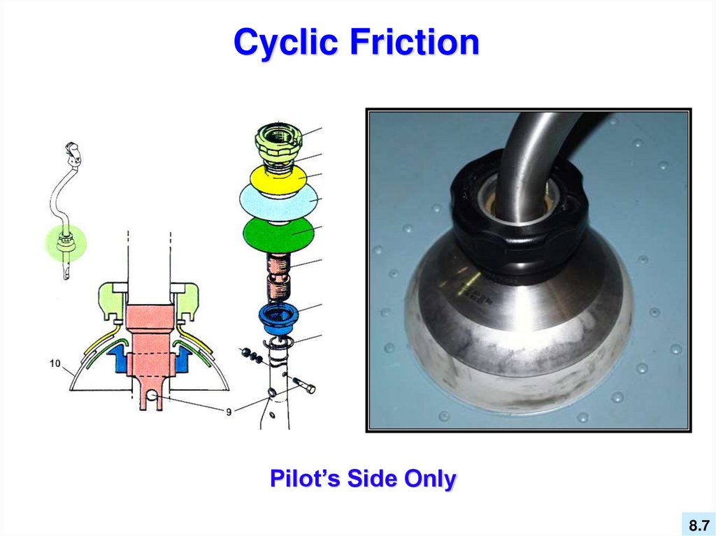
Cyclic FrictionPilot’s Side Only
8.7
8.
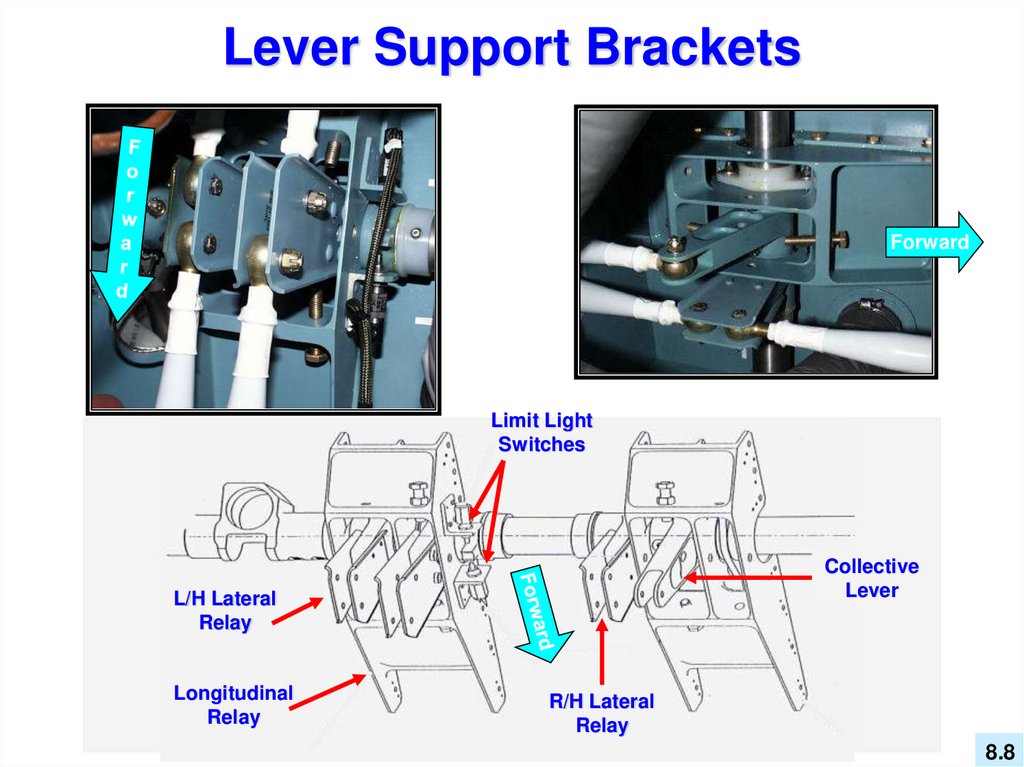
Lever Support BracketsForward
Limit Light
Switches
Collective
Lever
L/H Lateral
Relay
Longitudinal
Relay
R/H Lateral
Relay
8.8
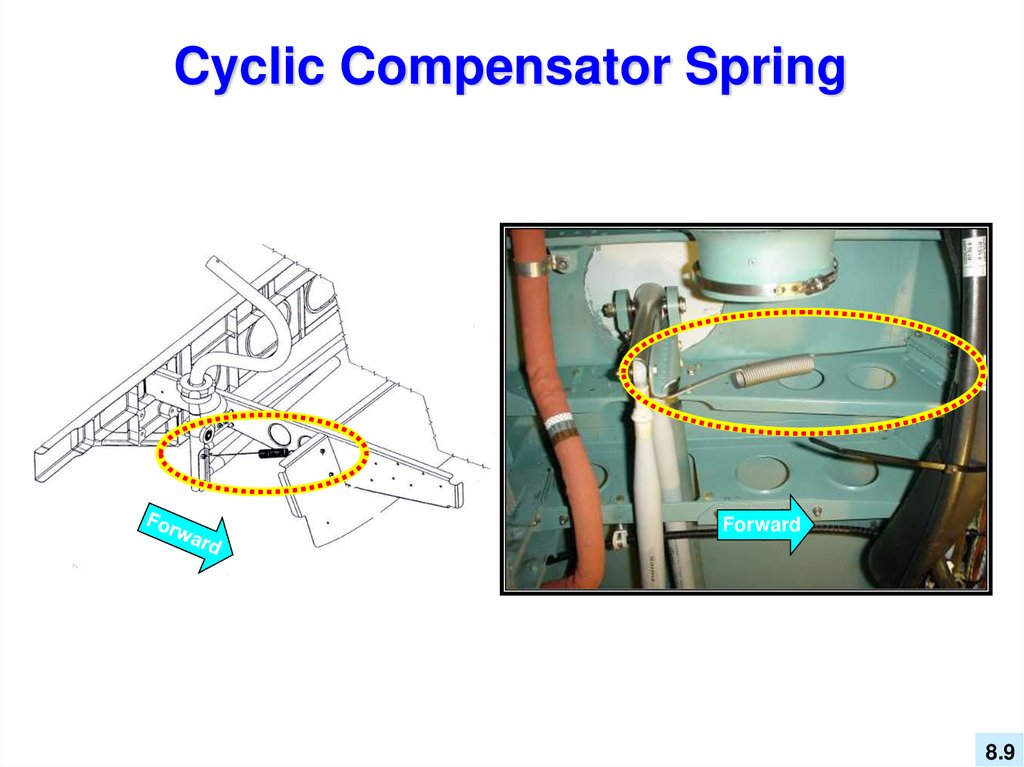
9.
Cyclic Compensator SpringForward
8.9
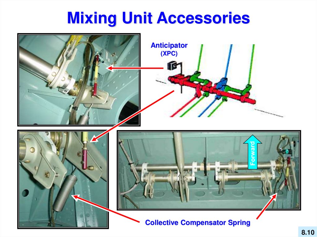
10.
Mixing Unit AccessoriesAnticipator
(XPC)
Collective Compensator Spring
8.10
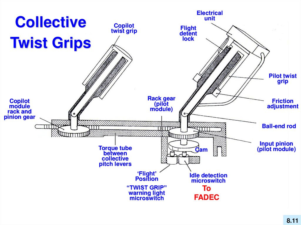
11.
CollectiveTwist Grips
Electrical
unit
Copilot
twist grip
Flight
detent
lock
Pilot twist
grip
Rack gear
(pilot
module)
Copilot
module
rack and
pinion gear
Friction
adjustment
Ball-end rod
Torque tube
between
collective
pitch levers
‘Flight’
Position
“TWIST GRIP”
warning light
microswitch
Cam
Input pinion
(pilot module)
Idle detection
microswitch
To
FADEC
8.11
12.
Collective Twist GripFixed Landing Light
Float
Arming
Switch
VEMD Scroll
Switch
Hoist
Cable
Cutter
Landing Light
Switch and
Swivel Button
8.12
13.
The “TWIST GRIP” Throttle - can be considered as a rolling switch....youare either in the Ground Idle position (NG approx. 67%), or the Flight
position. There is no modulation of the fuel, therefore, the throttle can not
be used to control yaw during an in-flight (cruise) emergency. The throttle is
used for starting and shutdown (IDLE), to simulate engine failures, and for
hovering tail rotor failures.
8.13
14.
Twist Grip ComponentsThe total ‘throw’ between the idle position and
the flight position is approximately 800 of travel.
There are no mechanical linkages between the
throttle and the fuel control, only microswitches.
Idle
Detection
Ramp
Return Coil
Spring
(spring loaded to
“Flight” position)
TWT
GRIP
Idle Switch
Out of ‘Flight’
Position Switch
8.14
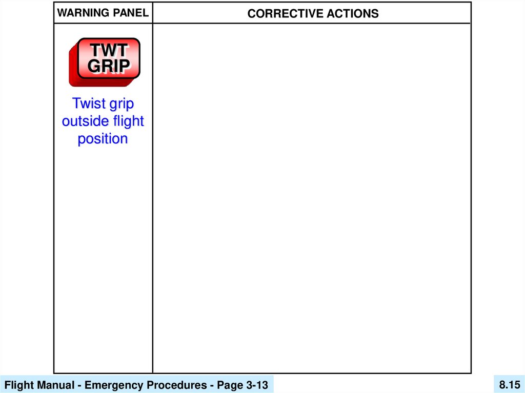
15.
WARNING PANELCORRECTIVE ACTIONS
TWT
GRIP
Twist grip
outside flight
position
Flight Manual - Emergency Procedures - Page 3-13
8.15
16.
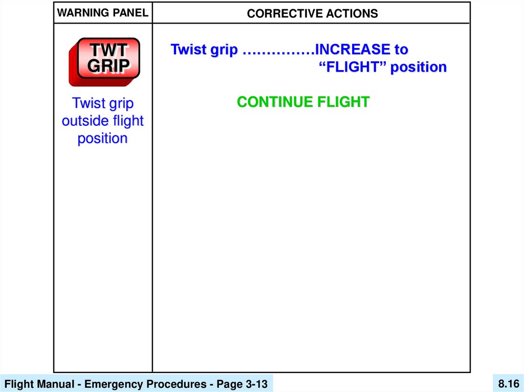
WARNING PANELCORRECTIVE ACTIONS
TWT
GRIP
Twist grip ……………INCREASE to
“FLIGHT” position
Twist grip
outside flight
position
CONTINUE FLIGHT
Flight Manual - Emergency Procedures - Page 3-13
8.16
17.
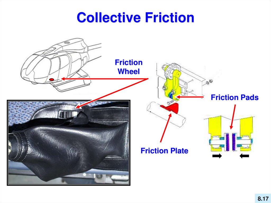
Collective FrictionFriction
Wheel
Friction Pads
Friction Plate
8.17
18.
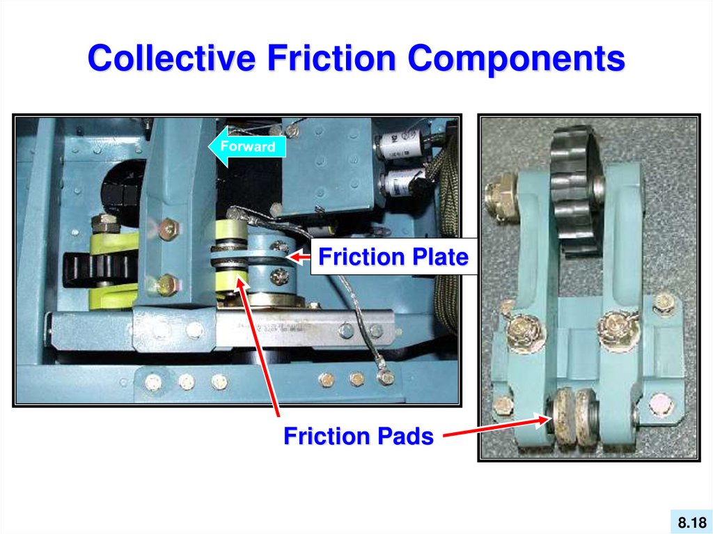
Collective Friction ComponentsFriction Plate
Friction Pads
8.18
19.
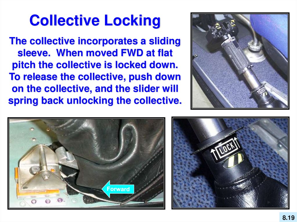
Collective LockingThe collective incorporates a sliding
sleeve. When moved FWD at flat
pitch the collective is locked down.
To release the collective, push down
on the collective, and the slider will
spring back unlocking the collective.
8.19
20.
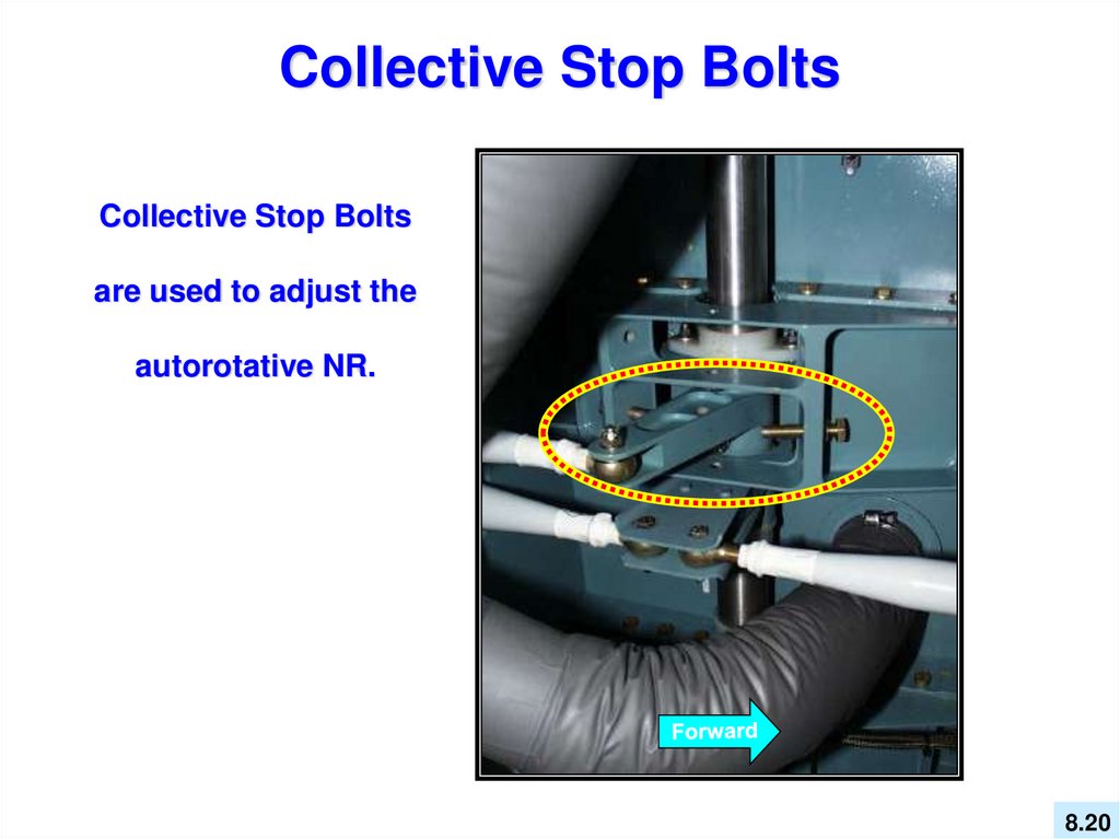
Collective Stop BoltsCollective Stop Bolts
are used to adjust the
autorotative NR.
8.20
21.
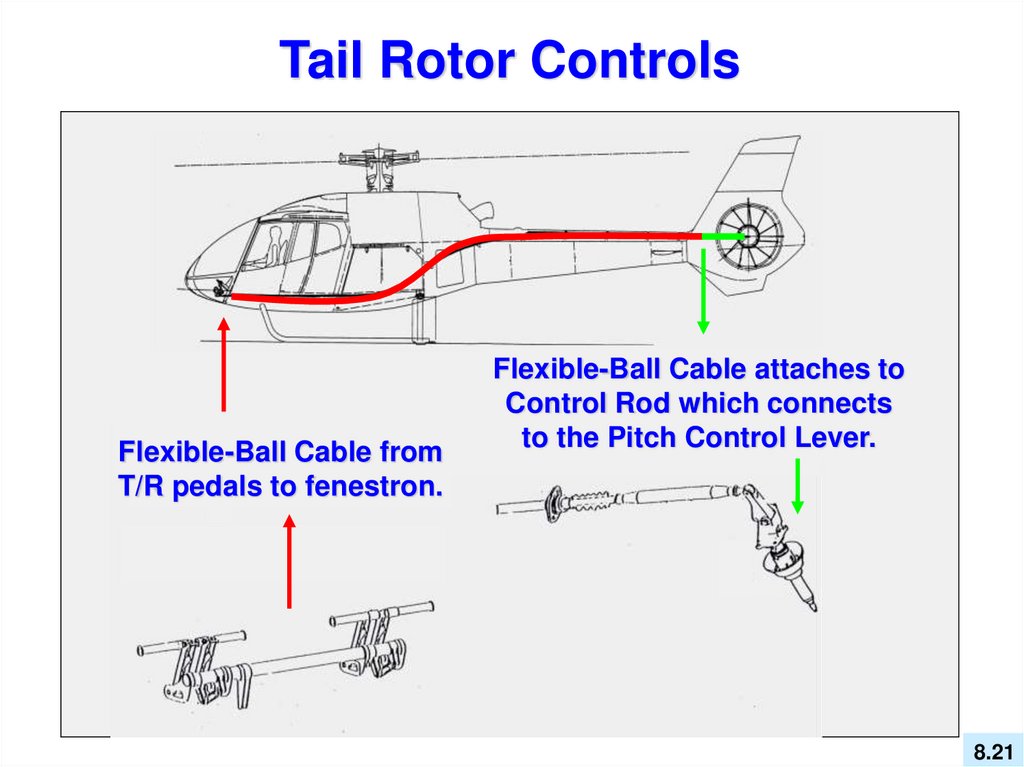
Tail Rotor ControlsFlexible-Ball Cable from
T/R pedals to fenestron.
Flexible-Ball Cable attaches to
Control Rod which connects
to the Pitch Control Lever.
8.21
22.
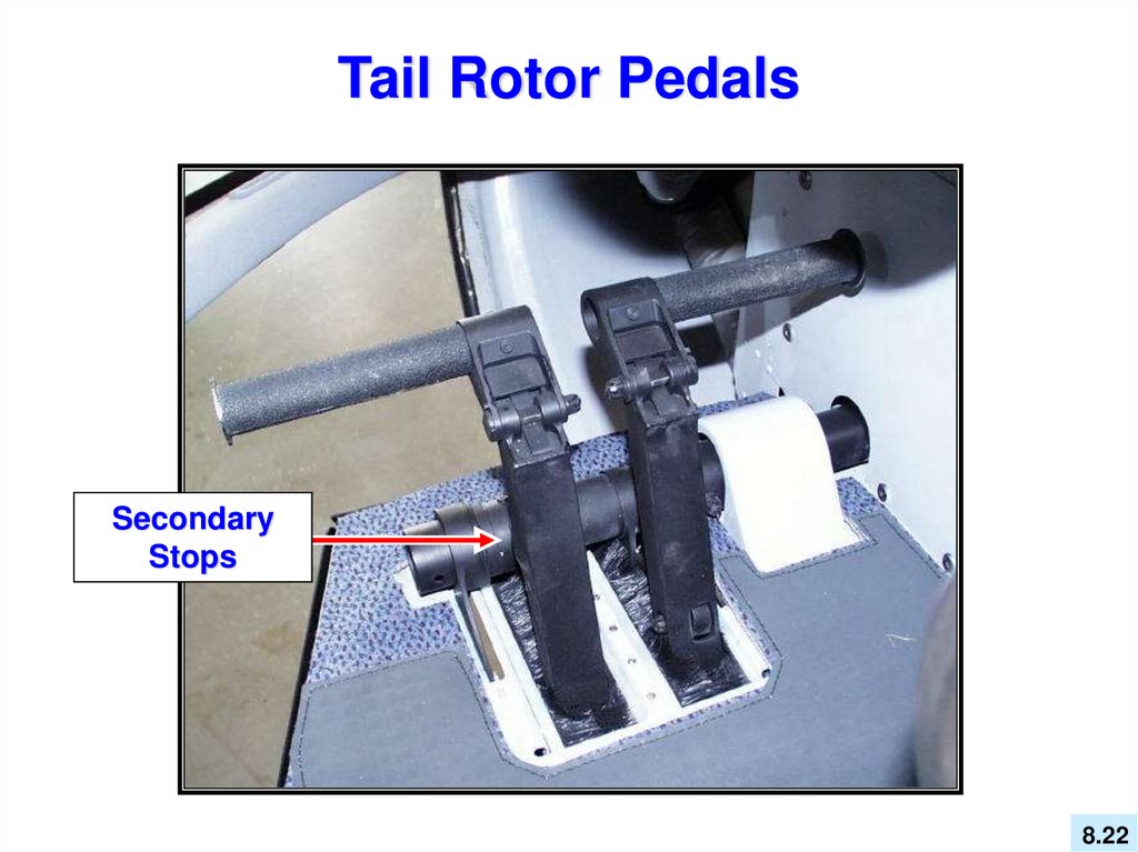
Tail Rotor PedalsSecondary
Stops
8.22
23.
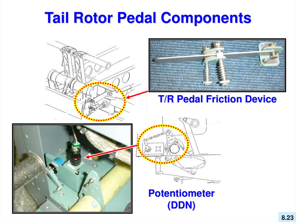
Tail Rotor Pedal ComponentsT/R Pedal Friction Device
Potentiometer
(DDN)
8.23
24.
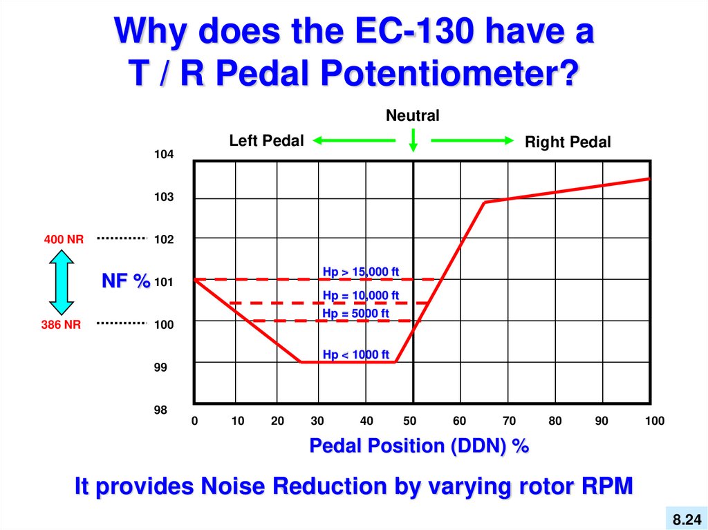
Why does the EC-130 have aT / R Pedal Potentiometer?
Neutral
Left Pedal
Right Pedal
104
103
400 NR
102
Hp > 15,000 ft
NF % 101
Hp = 10,000 ft
Hp = 5000 ft
386 NR
100
Hp < 1000 ft
99
98
0
10
20
30
40
50
60
70
80
90
100
Pedal Position (DDN) %
It provides Noise Reduction by varying rotor RPM
8.24
25.
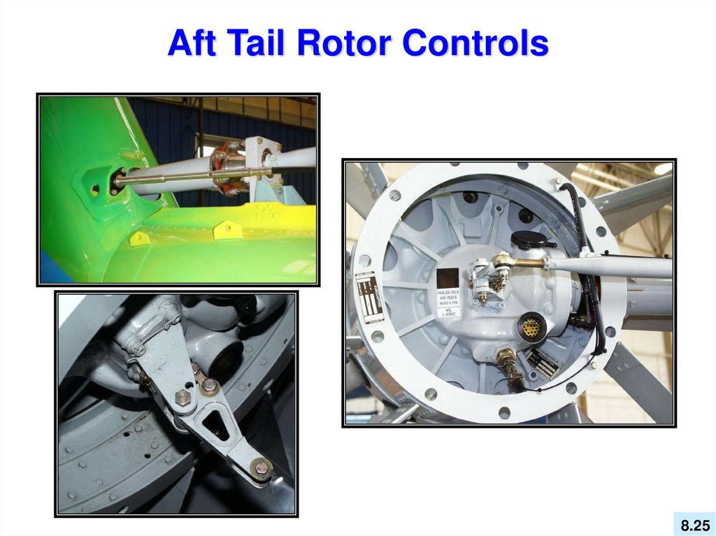
Aft Tail Rotor Controls8.25
26.
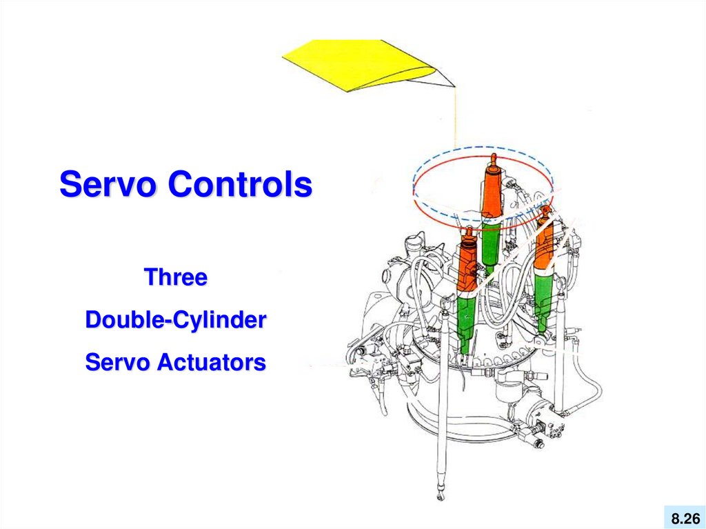
Servo ControlsThree
Double-Cylinder
Servo Actuators
8.26
27.
ServoActuators
Upper body
(LH hydraulics)
Servo Input Lever
Attaching Point
Lower body
(RH hydraulics)
8.27
28.
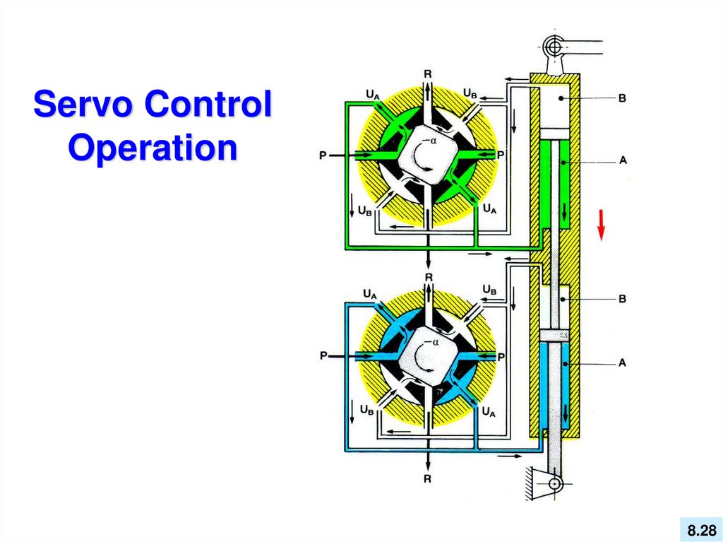
Servo ControlOperation
8.28
29.
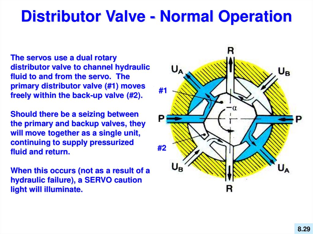
Distributor Valve - Normal OperationThe servos use a dual rotary
distributor valve to channel hydraulic
fluid to and from the servo. The
primary distributor valve (#1) moves
freely within the back-up valve (#2).
Should there be a seizing between
the primary and backup valves, they
will move together as a single unit,
continuing to supply pressurized
fluid and return.
#1
#2
When this occurs (not as a result of a
hydraulic failure), a SERVO caution
light will illuminate.
8.29
30.
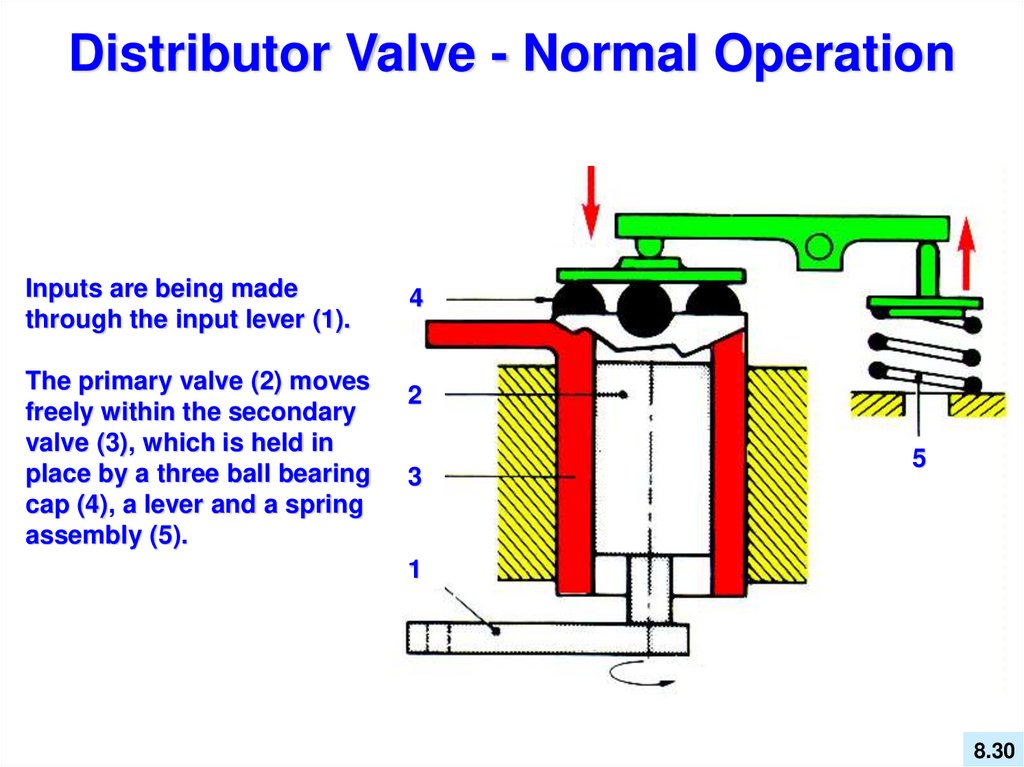
Distributor Valve - Normal OperationInputs are being made
through the input lever (1).
The primary valve (2) moves
freely within the secondary
valve (3), which is held in
place by a three ball bearing
cap (4), a lever and a spring
assembly (5).
4
2
3
5
1
1
8.30
31.
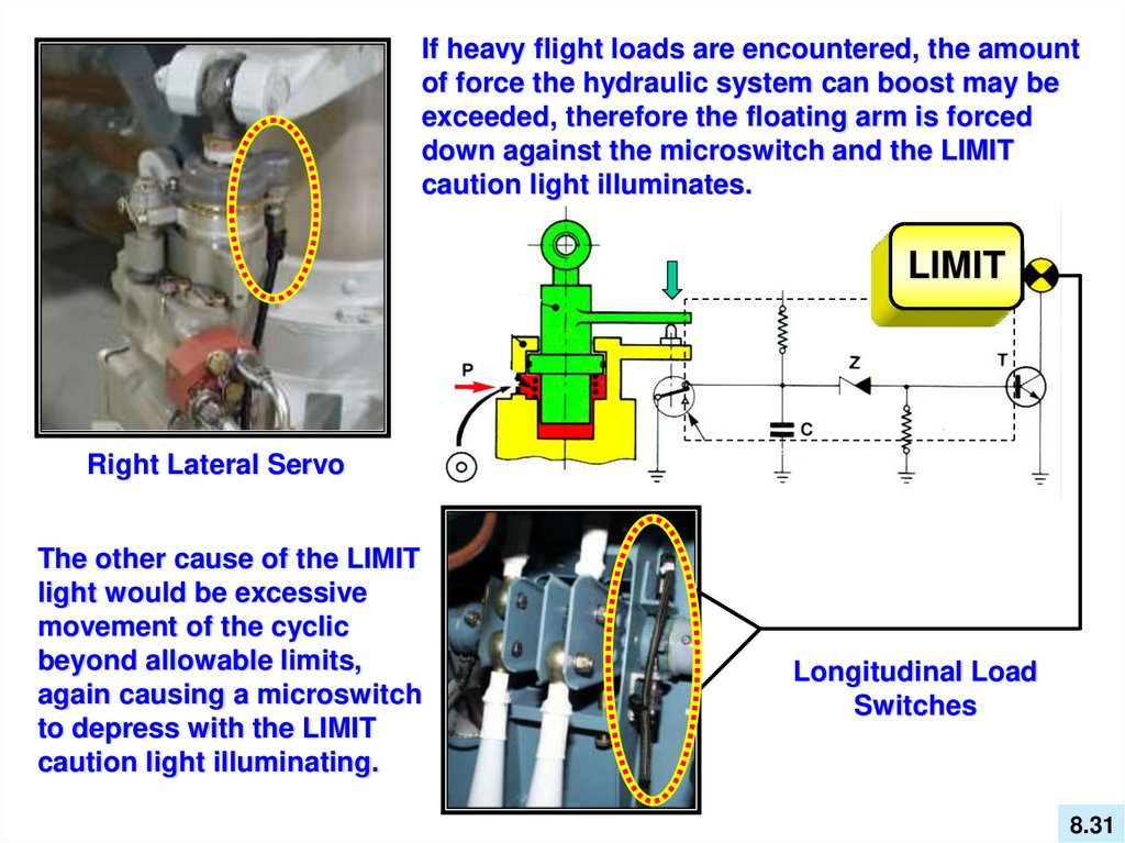
If heavy flight loads are encountered, the amountof force the hydraulic system can boost may be
exceeded, therefore the floating arm is forced
down against the microswitch and the LIMIT
caution light illuminates.
LIMIT
Right Lateral Servo
The other cause of the LIMIT
light would be excessive
movement of the cyclic
beyond allowable limits,
again causing a microswitch
to depress with the LIMIT
caution light illuminating.
Longitudinal Load
Switches
8.31
32.
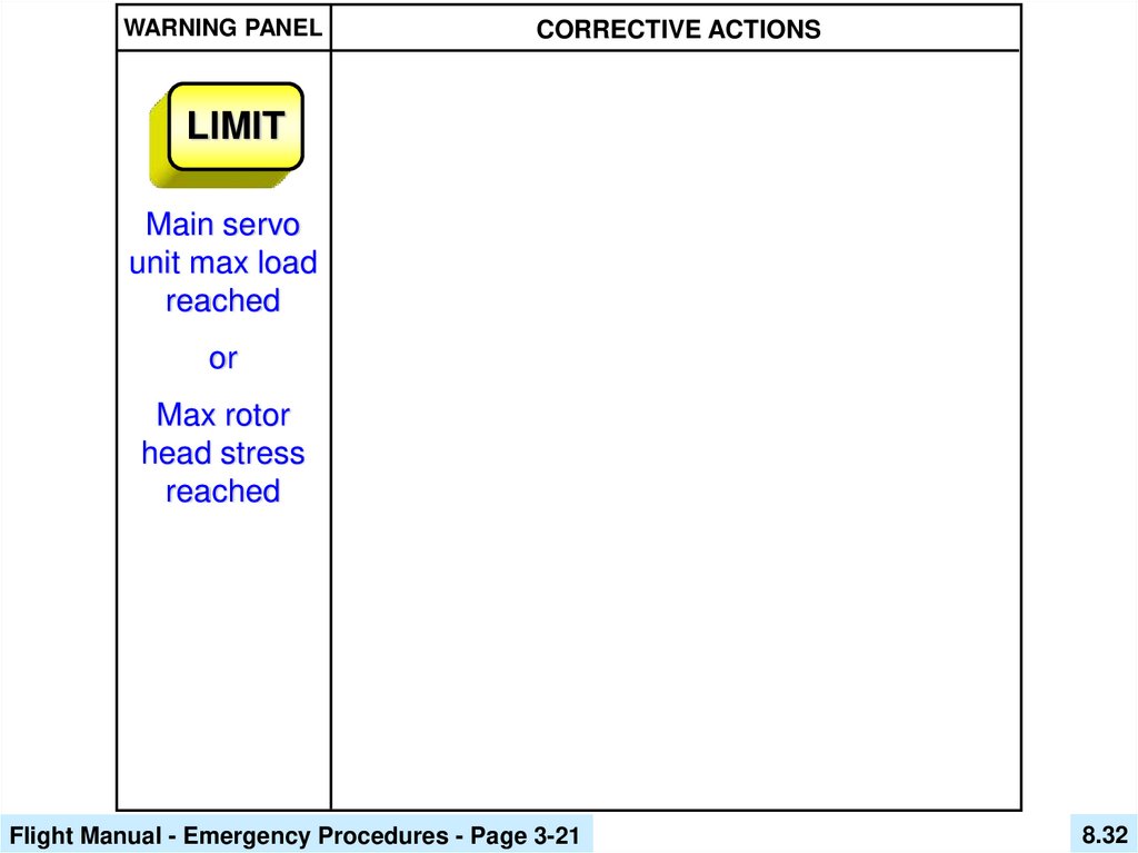
WARNING PANELCORRECTIVE ACTIONS
LIMIT
Main servo
unit max load
reached
or
Max rotor
head stress
reached
Flight Manual - Emergency Procedures - Page 3-21
8.32
33.
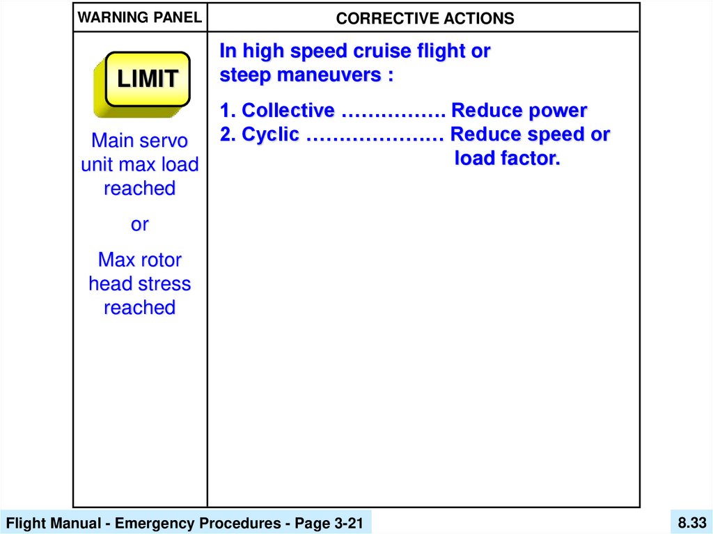
WARNING PANELLIMIT
Main servo
unit max load
reached
CORRECTIVE ACTIONS
In high speed cruise flight or
steep maneuvers :
1. Collective ……………. Reduce power
2. Cyclic ………………… Reduce speed or
load factor.
or
Max rotor
head stress
reached
Flight Manual - Emergency Procedures - Page 3-21
8.33
34.
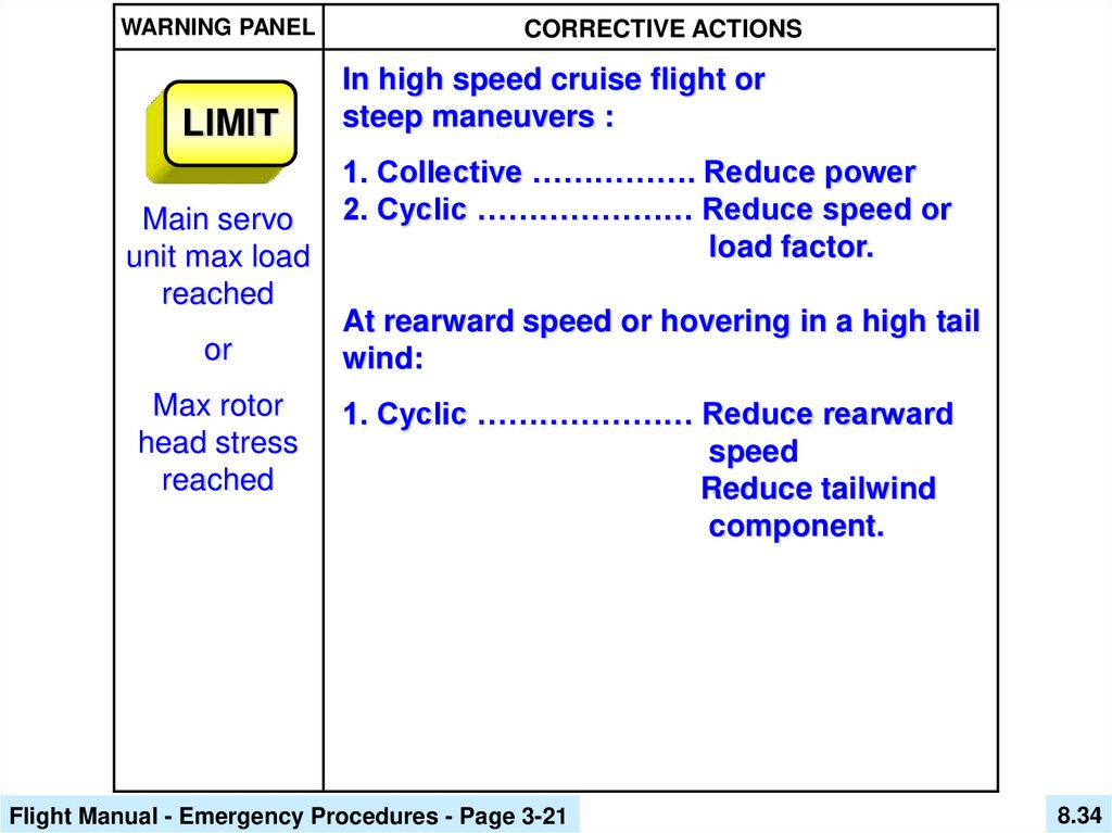
WARNING PANELLIMIT
Main servo
unit max load
reached
or
Max rotor
head stress
reached
CORRECTIVE ACTIONS
In high speed cruise flight or
steep maneuvers :
1. Collective ……………. Reduce power
2. Cyclic ………………… Reduce speed or
load factor.
At rearward speed or hovering in a high tail
wind:
1. Cyclic ………………… Reduce rearward
speed
Reduce tailwind
component.
Flight Manual - Emergency Procedures - Page 3-21
8.34
35.
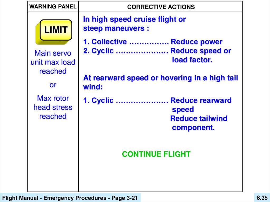
WARNING PANELLIMIT
Main servo
unit max load
reached
or
Max rotor
head stress
reached
CORRECTIVE ACTIONS
In high speed cruise flight or
steep maneuvers :
1. Collective ……………. Reduce power
2. Cyclic ………………… Reduce speed or
load factor.
At rearward speed or hovering in a high tail
wind:
1. Cyclic ………………… Reduce rearward
speed
Reduce tailwind
component.
CONTINUE FLIGHT
Flight Manual - Emergency Procedures - Page 3-21
8.35
36.
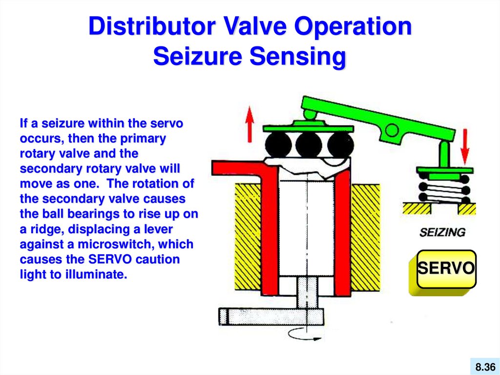
Distributor Valve OperationSeizure Sensing
If a seizure within the servo
occurs, then the primary
rotary valve and the
secondary rotary valve will
move as one. The rotation of
the secondary valve causes
the ball bearings to rise up on
a ridge, displacing a lever
against a microswitch, which
causes the SERVO caution
light to illuminate.
SERVO
8.36
37.
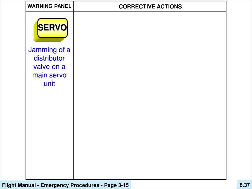
WARNING PANELCORRECTIVE ACTIONS
SERVO
Jamming of a
distributor
valve on a
main servo
unit
Flight Manual - Emergency Procedures - Page 3-15
8.37
38.
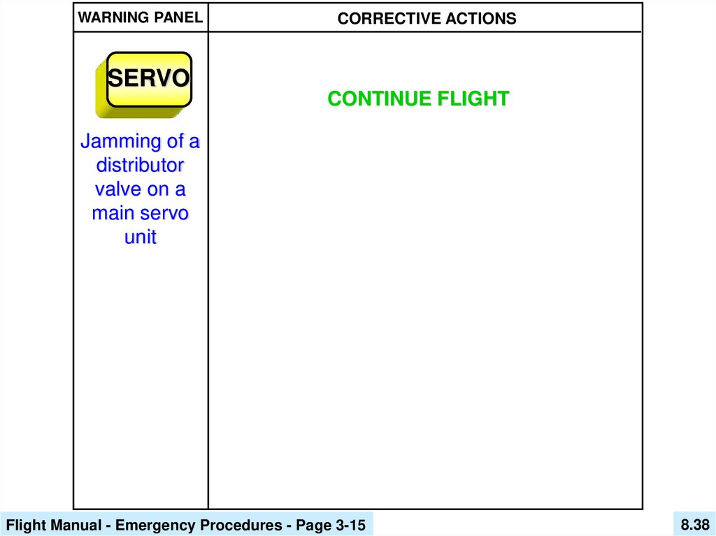
WARNING PANELCORRECTIVE ACTIONS
SERVO
CONTINUE FLIGHT
Jamming of a
distributor
valve on a
main servo
unit
Flight Manual - Emergency Procedures - Page 3-15
8.38
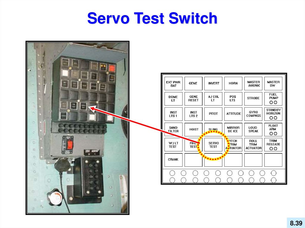
39.
Servo Test Switch8.39
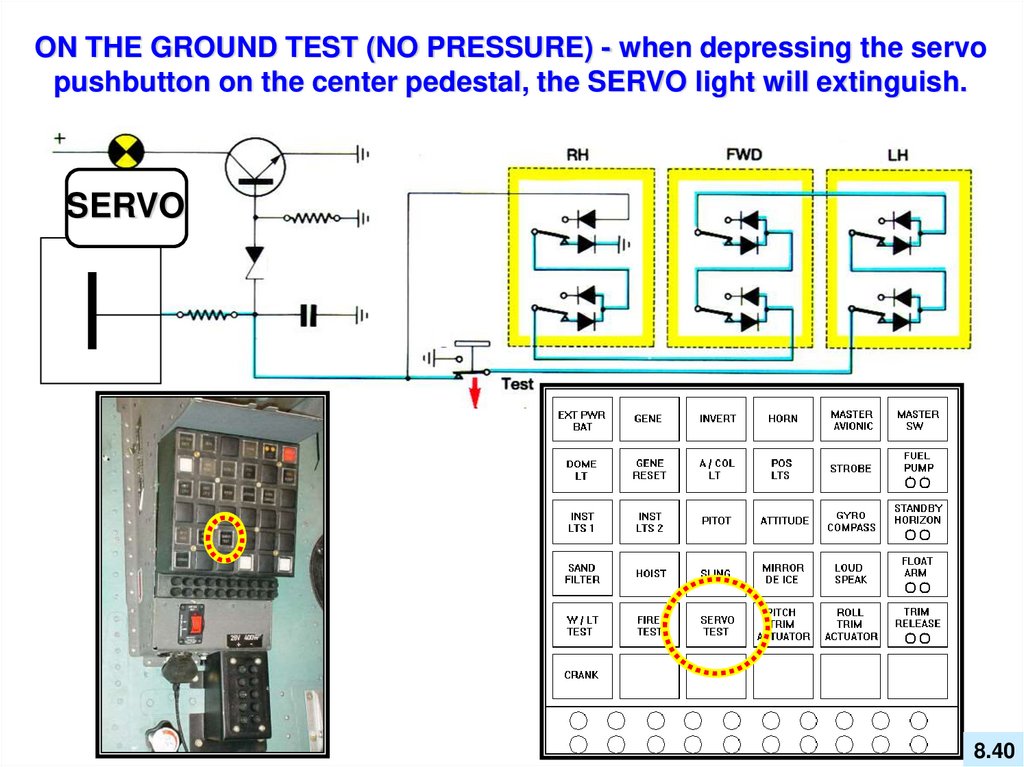
40.
ON THE GROUND TEST (NO PRESSURE) - when depressing the servopushbutton on the center pedestal, the SERVO light will extinguish.
SERVO
SERVO
8.40
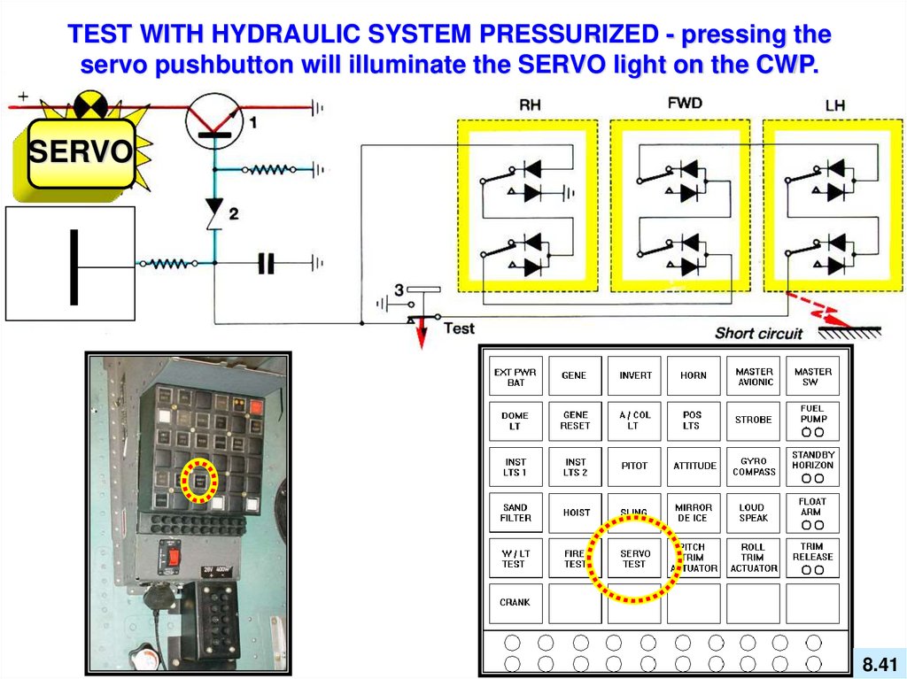
41.
TEST WITH HYDRAULIC SYSTEM PRESSURIZED - pressing theservo pushbutton will illuminate the SERVO light on the CWP.
SERVO
8.41
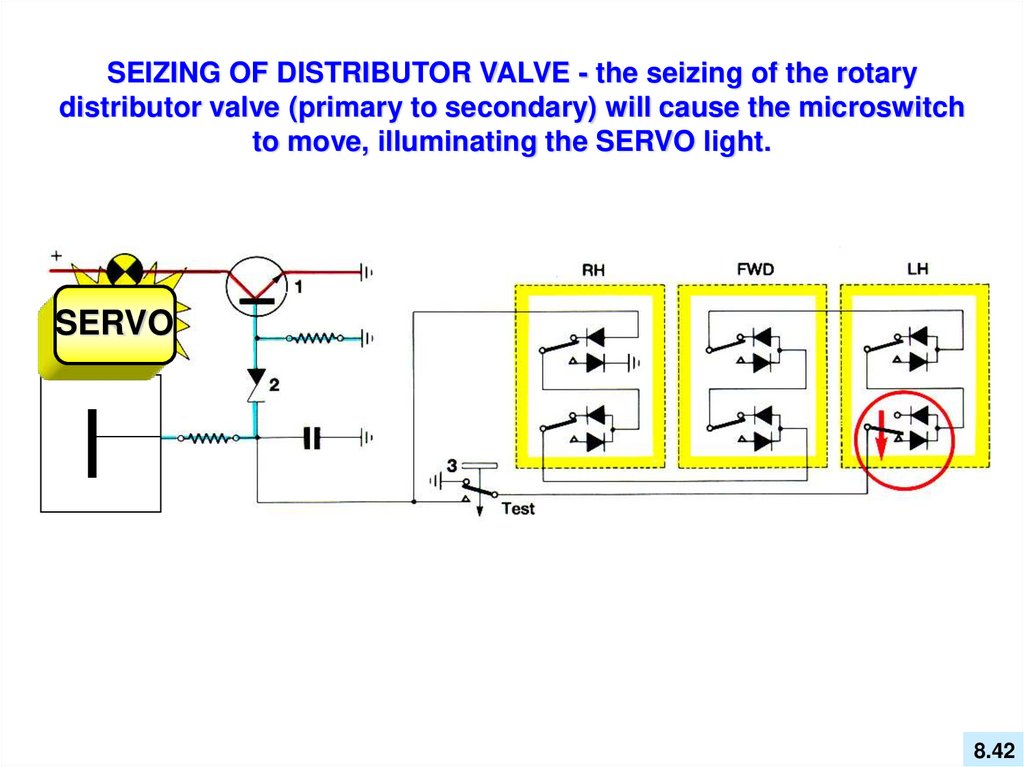
42.
SEIZING OF DISTRIBUTOR VALVE - the seizing of the rotarydistributor valve (primary to secondary) will cause the microswitch
to move, illuminating the SERVO light.
SERVO
8.42
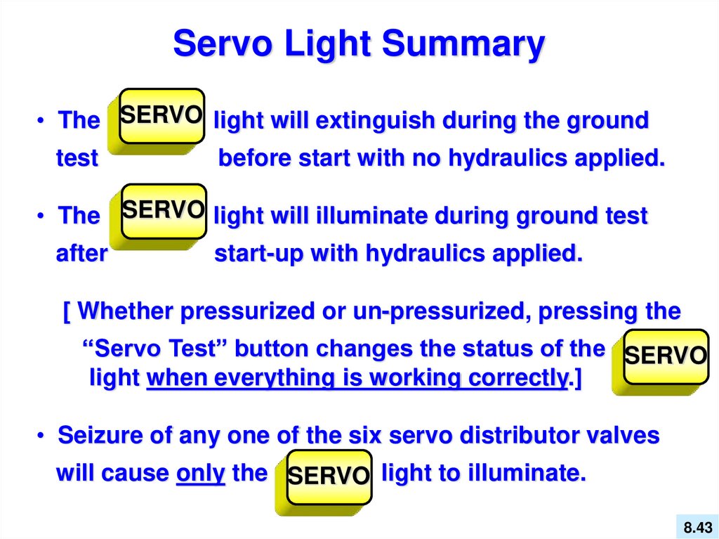
43.
Servo Light Summary• The SERVO light will extinguish during the ground
test
before start with no hydraulics applied.
• The SERVO light will illuminate during ground test
after
start-up with hydraulics applied.
[ Whether pressurized or un-pressurized, pressing the
“Servo Test” button changes the status of the SERVO
light when everything is working correctly.]
• Seizure of any one of the six servo distributor valves
will cause only the SERVO light to illuminate.
8.43
44. Review Questions
8.4445.
68. What are the main components in themain rotor / tail rotor flight system controls?
B. Push-pull tubes and bell cranks / flexball
cable and a push-pull tube.
46.
69. What is the purpose of the mixing unit?D. Sum (add) the cyclic inputs with the
collective inputs.
47.
70. Which main rotor servo moves to pitchthe aircraft nose up or down?
A. The left forward servo.
48.
71. What adjustments need to be madefor an autorotation rpm change IAW
Section 8 of the Flight Manual?
D. Low pitch adjustment stop / lock strip
(down-stop bolt).
49.
72. How many hydraulic servos areutilized in the EC130 B4?
A. Three dual bodied servos.
50.
73. When the pilot inputs control forcesthrough the flight controls to the servo stops,
where does the distributor valve stop?
D. Hydraulic zero.
51.
74. What are the separate aerodynamicfunctions of the three servos?
B. Right lateral (roll), left lateral (roll),
and pitch (longitudinal).
52.
75. What is the upper rod end bearing ofeach main servo attached to?
D. Non-rotating swashplate.
53.
76. What is the lower rod end bearing ofeach main servo attached to?
A. Conical housing of the main gear box.
54.
77. What happens to the SERVO light whenthe SERVO TEST pushbutton on the console
is pressed & everything is working correctly?
C. The status (illuminate / extinguish) of the
SERVO caution light will change.
55.
78. On the tail rotor servo, what attachesto the pilot control input lever and provides
input from the yaw pedals?
C. There is no tail rotor servo on this aircraft.
56.
79.What type of control linkage interconnectsthe cyclic, collective, and the swashplate?
D. Rigid control tubes.
57.
80. What component allows the collectiveand cyclic to interface without interference?
A. The mixing unit.
58.
EC 130 B4Initial Pilot Ground School
End of Chapter 8
Flight Controls
and Servo Controls