


")


 internet
Similar presentations:


")


Computer Networks
1. Computer Networks
TEACHER: TOLEGEN DANAD .TO L E G E N @ A S TA N A I T. E D U . K Z
2. Course Plan
The course Computer Networks is designed as a 10-week program consisting of lectures, practice sessions, teachersupervised independent study (TSIS), and student independent study (SIS), with a total workload of 150 hours (5 ECTS).Each week covers both theoretical concepts and practical applications, supported by independent assignments. Topics
progress from fundamentals of networking to advanced issues of network security:
Week 1 – Network Fundamental, Wire Networks, Wireless Networks, Cisco Networks
Week 2 – Computer Networking, Networks Connections, Network Classifications, Network Technologies, Network
Architectures
Week 3 – Networks Fundemental, Multiple Access Scheme, Switching, Standardization
Week 4 – Network Access, Wireless Local Area Network (WLAN) - Introduction
Week 5 – Network Access, Wireless Local Area Network (WLAN): IEEE 802.11 Family; IEEE 802.11 Family Physical
Layer; IEEE 802.11 Family Data Link Layer; VLANs; Inter-VLAN Routing; WLAN Configuration; Ch-5: STP Concepts:
Week 6 – Reference Models, OSI Reference Model, TCP/IP Reference Model
Week 7 – Application Layer, Transport Layer
Week 8 – Network Layer, Internet Protocol (IP), Routing Process
Week 9 – Network Layer, Routing Algorithms, IP Static Routing, Basic Device Configuration, Other Significant Protocols
Week 10 – Data Link Layer, Physical Layer
3. Course Policy
Presence and ParticipationStudents are expected to attend all scheduled class sessions with the required readings and supplementary materials completed beforehand.
Attendance itself does not provide extra points, but it is mandatory for course completion. Students must participate in at least 70% of all
class sessions; otherwise, they will not be admitted to the exam and will fail the course. Active participation is expected and will be evaluated
by the quality of contributions, such as offering unique perspectives, advancing discussion, and building on peers’ comments. Being more
than 15 minutes late results in being marked absent. Also if you leave the meeting without warning, I will put on absent.
Deadlines and Late Submissions
All assignments and homework must be submitted on time. Since assignments are often discussed in class on the due date, late submissions
will not be accepted. Submissions through Moodle after the deadline will automatically reduce the overall score by 30%. In exceptional
circumstances, students may request an extension in advance with proper justification; if approved, a new deadline will be assigned.
Please also keep in mind that the dean's office is no longer at the university and it will be more difficult to get help in case of illness. You
will not be given an order easily, so try not to miss classes, especially since they are online.
4. Evaluation system for the course
Period1st attestation
2nd attestation
Assignments*
Number of points
Form of assessment
Assignment 1
15
Assignment 2
15
Assignment 3
15
Assignment 4
15
Midterm exam
40
Assignment 5
15
Assignment 6
15
Assignment 7
15
Assignment 8
15
submission of Cisco
CCNA certification
Endterm exam
40
Cisco Packet Tracer
(PA)
Total
100
average of all
assignments in week 5
100
Final exam
Exam (Paper based MCQ + Open Questions)
100
Total
0.3*1 st Att + 0.3 *2 nd Att + 0,4 + Final
100
5. Tasks for week 1:
1. Create a Cisco NetAcad Account. Cisco Packet Tracer is provided by CiscoNetworking Academy (NetAcad).
Go to https://www.netacad.com/
Click Sign Up (or Log In if you already have an account)
2. Download Packet Tracer
After enrolling, go to the Resources section of the course.
Select Download Packet Tracer.
Choose Windows 64-bit (or 32-bit if needed).
It will download an .exe installer file.
3. Install on WindowsRun the downloaded .exe file.
Follow the installation steps:
• Accept the license
• Choose the installation folder
• Complete the setup
6.
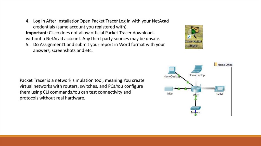
4. Log In After InstallationOpen Packet Tracer.Log in with your NetAcadcredentials (same account you registered with).
Important: Cisco does not allow official Packet Tracer downloads
without a NetAcad account. Any third-party sources may be unsafe.
5. Do Assignment1 and submit your report in Word format with your
answers, screenshots and etc.
Packet Tracer is a network simulation tool, meaning:You create
virtual networks with routers, switches, and PCs.You configure
them using CLI commands.You can test connectivity and
protocols without real hardware.
7. Basic Networking Concepts
Before you start configuring networks, you need to understand what a network is and how it operates.•What is a Network?
A network is a collection of devices (computers, printers, routers, switches) connected to share data and resources.
Example: Your home Wi-Fi connects your laptop, smartphone, and printer together.
•Types of Networks:
• LAN (Local Area Network): A small network within a limited area like an office or home.
• WAN (Wide Area Network): A large network that connects multiple LANs (e.g., the Internet).
• MAN (Metropolitan Area Network): Connects networks within a city.
• PAN (Personal Area Network): Small network for personal devices (e.g., Bluetooth).
•Network Devices:
• End Devices: PCs, laptops, servers, printers.
• Networking Devices: Routers, switches, hubs.
•Data Transmission Basics:
• Data is transmitted in packets (chunks of information).
• Each packet has source IP, destination IP, and other details.
8. OSI and TCP/IP Models
Understanding how data flows in a network is crucial.•OSI Model (7 Layers):
• Physical: Cables, signals.
• Data Link: MAC addresses, switches.
• Network: IP addresses, routing.
• Transport: TCP/UDP.
• Session: Manages sessions.
• Presentation: Data formatting, encryption.
• Application: User interaction (HTTP, FTP).
•TCP/IP Model (4 Layers):
• Network Access: Physical + Data Link.
• Internet: IP addressing, routing.
• Transport: TCP/UDP.
• Application: End-user protocols.
Why it matters in Packet Tracer?
When troubleshooting, you can identify which layer is causing a problem.
9. IP Addressing and Subnetting
•IP Address: A unique identifier for a device in a network (e.g., 192.168.1.10).•Subnet Mask: Defines the network and host portion (e.g., 255.255.255.0).
•Default Gateway: The IP address of the router that connects your LAN to other networks.
•Subnetting: Dividing a network into smaller networks for efficiency and security.
• Example: 192.168.1.0/24 means 256 IPs (254 usable hosts).
Practice: Assign IP addresses to devices in Packet Tracer and use ping to test connectivity.
•Router: Connects different networks and makes routing decisions.
•Switch: Connects multiple devices in a LAN and forwards frames based on MAC addresses.
•Hub: Broadcasts data to all devices (outdated).
•Access Point (AP): Provides wireless connectivity.
•Firewall: Controls network traffic for security.
10. Cisco CLI Commands (Basics)
In Packet Tracer, you configure devices using the Cisco Command Line Interface (CLI). Commoncommands:
•enable → Enter privileged EXEC mode.
•configure terminal → Enter global configuration mode.
•hostname Router1 → Set device name.
•interface FastEthernet 0/0 → Enter an interface configuration.
•ip address 192.168.1.1 255.255.255.0 → Assign IP to interface.
•no shutdown → Activate the interface.
•ping [IP] → Test connectivity.
11. Common Protocols
•TCP vs UDP:•TCP: Reliable, connection-oriented (e.g., HTTP, FTP).
•UDP: Faster, no error-checking (e.g., video streaming, DNS).
•HTTP/HTTPS: Web traffic.
•DNS: Resolves domain names to IP addresses.
•DHCP: Automatically assigns IP addresses.
•ICMP: Used by ping to check connectivity.
12. Network Topology
The physical and logical structure of a network:•Star: All devices connected to a central switch
(most common).
•Bus: Single backbone cable (outdated).
•Ring: Devices connected in a circle.
•Mesh: Every device connects to every other
device (high redundancy).
13. Task 1: Create a Basic LAN
Goal: Connect 2 PCs and test connectivity.Steps:
1.Drag 2 PCs and 1 Switch into the workspace.
2.Connect PCs to the switch using Copper Straight-Through cables.
3.Assign IP addresses manually:
1. PC1: 192.168.1.1 / 255.255.255.0
2. PC2: 192.168.1.2 / 255.255.255.0
4.Test with ping:
1. From PC1 → PC2: ping 192.168.1.2
14. Task 2: Add a Router to Connect 2 LANs
Goal: Connect two networks using a router.Steps:
1.Create two switches, each with 2 PCs.
2.Add 1 Router and connect each switch to a router interface.
3.Assign IPs:
1. LAN1: 192.168.1.0/24
2. LAN2: 192.168.2.0/24
4.On the router:
1.interface fa0/0 → ip address 192.168.1.1
255.255.255.0
2.interface fa0/1 → ip address 192.168.2.1
255.255.255.0
3.no shutdown
5.On PCs, set Default Gateway as the router’s interface IP.
6.Test ping across networks.
15. Task 3: Configure DHCP
Goal: Use DHCP to automatically assign IP addresses.Steps:
1.Add a Router, Switch, and 3 PCs.
2.Configure the router as a DHCP server:
Router> enable
Router# configure terminal
Router(config)# ip dhcp pool LAN
Router(dhcp-config)# network 192.168.10.0 255.255.255.0
Router(dhcp-config)# default-router 192.168.10.1
Router(dhcp-config)# exit
Router(config)# interface fa0/0
Router(config-if)# ip address 192.168.10.1 255.255.255.0
Router(config-if)# no shutdown
3. On PCs, set IP Configuration → DHCP.
4.Test connectivity.
16. Task 4: Create VLANs on a Switch
Goal: Separate two groups of PCs into VLANs.Steps:
1.Add 1 Switch and 4 PCs.
2.Assign:
1. PC1 & PC2 → VLAN 10
2. PC3 & PC4 → VLAN 20
3.Configure the switch:
Task 4: Create
VLANs on a
Switch
Switch> enable
Switch# configure terminal
Switch(config)# vlan 10
Switch(config-vlan)# name HR
Switch(config-vlan)# exit
Switch(config)# vlan 20
Switch(config-vlan)# name IT
Switch(config-vlan)# exit
Switch(config)# interface fa0/1
Switch(config-if)# switchport mode access
Switch(config-if)# switchport access vlan 10
(repeat for other ports)
1.Assign IPs in the same VLAN range.
2.Ping PCs within the same VLAN.
17. Task 5: Static Routing Between Two Routers
Goal: Connect 3 LANs via 2 routers.Steps:
1.Add 2 Routers, 2 Switches, and 4 PCs.
2.Configure IP addresses for each LAN and router interfaces.
3.Add static routes:
4.Router1(config)# ip route 192.168.2.0
255.255.255.0 10.0.0.2
5.Router2(config)# ip route 192.168.1.0
255.255.255.0 10.0.0.1
6.Test connectivity between PCs in different LANs.