


")
")


")


")
")
")
")

")
")
")
")


")


 informatics
Similar presentations:


A over IP Workshop
1. A over IP Workshop
Design & MigrationMobile
Packet
Back Bone
2. All IP MSS transport
› IP as converged transport technologyfor all network domains (Access, CS
Core, PS Core, IMS etc.)
Today
IMS
BSC
› Scales easy with growing traffic
TDM
TDM
M-MGw
MSC-S
IP transport
POI
TDM
RNC
ATM
› Bandwidth efficiency through
compressed speech and IP
Multiplexing
› Superior speech experience: End-toEnd TrFO and Wideband speech
interworking across interconnect
border
A over IP
MSS All IP
IMS
BSC
IP
M-MGw
MSC-S
IP transport
RNC
IP
Iu over IP
Nb over IP
IP
Mb
All-IP in CN and towards RAN and POI
Ericsson Internal | 2011-12-22 | Page 2
POI
3. Iu/A-interface over IP
MSC poolBSSAP/
RANAP
SCCP
M3UA
SCTP
IP
MSC-S
MSC-S
Single MGw selected
per call
A-i/f at the network edge,
local MGw not used for
remote calls
GSM transcoders moved
from BSS to MGw
GCP
AMR/EFR over RTP/UDP/IP
BSC/RNC
Local site
MGw pool
M-MGw
Remote site
M-MGw
MGw at local site for
local switching
Bandwidth efficiency
through IP multiplexing
Transcoder Free
Operation
Telecom quality GSM services over IP
Efficient usage of network and node resources
Ericsson Internal | 2011-12-22 | Page 3
4. 2G Transcoder Free Operation
BICCNo
transcoder
BSSAP
MSC-S
GCP
TrFO with AMR,
EFR, HR, FR and
WB-AMR
M-MGw
End-to-End TrFO improves
speech quality and saves
transcoding resources
BSSAP
No
transcoders
GCP
Nb/RTP/UDP/IP
A over IP
BSC
MSC-S
A over IP
M-MGw
BSC
TrFO with AMR HR, resource savings in
radio, core and transport networks
Improved Speech Quality and
resource savings in radio, core and transport networks
Ericsson Internal | 2011-12-22 | Page 4
5. AoIP & TrFO benefit compared to PCM in CN => 46% less transcoders
AoIP & TrFO benefit compared to PCM in CN=> 46% less transcoders
1 transcoder in mobile to
PSTN/PLMN
PSTN/PLMN calls (70%)
A over
TDM
A over
TDM
M-MGw
BSC
BSC
2 transcoders in mobile-to-mobile calls (30%)
1 transcoder in mobile to
PSTN/PLMN
PSTN/PLMN calls (70%)
AoIP
BSC
AoIP
M-MGw
BSC
No transcoders in mobile-to-mobile calls (30%)
Ericsson Internal | 2011-12-22 | Page 5
6. AoIP & TrFO benefit compared to compr. speech on Nb => 65% less transcoders
AoIP & TrFO benefit compared to compr. speech on Nb=> 65% less transcoders
-4 transcoders in 30% of calls
-3 transcoders in 15% of calls
-1 transcoder in 55% of calls
PSTN/PLMN
MSC-S
MSC-S
Compressed
speech over Nb-i/f
A over
TDM
M-MGw
BSC
A over
TDM
M-MGw
BSC
45% of the calls between two M-MGws
MSC-S
AoIP M-MGw
BSC
-No transcoders in 30% of calls
-1 transcoders in 15% of calls
-1 transcoder in 55% of calls
PSTN/PLMN
AoIP
AoIP
M-MGw
No calls with 2 M-MGws due to extended A-i/f
Ericsson Internal | 2011-12-22 | Page 6
BSC
7. M-MGw pool enables load distribution and N+1 redundancy => 33% capacity gain
M-MGw pool enables load distribution and N+1 redundancy=> 33% capacity gain
1+1 redundancy
A over
TDM
12 kE
12 kE
M-MGw
M-MGw
12 kE
IP backbone
A over
TDM
12 kE
BSC
BSC
Dedicated M-MGw
nodes per BSC
Distributed load and
N+1 redundancy among
M-MGw nodes
12 kE
12 kE
M-MGw
M-MGw
8 kE
8 kE
M-MGw
M-MGw
M-MGw capacity on
network level is 48 kE
M-MGw capacity on
network level is 32 kE
IP backbone
12 kE
12 kE
BSC
BSC
8 kE
M-MGw
Ericsson Internal | 2011-12-22 | Page 7
8 kE
M-MGw
33% less capacity is
needed
8. AoIP & flexible M-MGw selection => 31% less M-MGw SCC:s
AoIP & flexible M-MGw selection=> 31% less M-MGw SCC:s
PSTN/PLMN
MSC-S
A over
TDM
BSC
MSC-S
A over
TDM
Nb-i/f
M-MGw
One call consumes
capacity X
M-MGw
BSC
One call consumes
capacity Y
45% of the calls with 2 SCC:s
PSTN/PLMN
MSC-S
AoIP M-MGw
AoIP
AoIP
M-MGw
BSC
No calls with 2 SCC:s due to extended A-i/f
Ericsson Internal | 2011-12-22 | Page 8
Two virtual MGw:s
MSC-S
BSC
One call consumes
capacity X+Y
9. Pre-requisites
› The recommended minimum node revision levels for AoIP support are:MSC-S and MSC-S BC R14.1
M-MGw R6.1(A new Ericsson proprietary GCP profile, EP7
(“Ericsson_FAY112190_1/1”), has been developed to support AoIP related
procedures/parameters, as well the new codecs.)
BSS G10B
› Required Optional Node Features for AoIP
MSC-S and MSC-S BC, M-MGw and BSC: A interface over IP
› Recommended Optional Node Features for AoIP
MSC-S and MSC-S BC: Transcoder Free Operation (TrFO)
M-MGw: Compressed Speech on Nb Interface
Measurement Based Admission Control
Bandwidth Efficiency with IP Multiplexing
Ericsson Internal | 2011-12-22 | Page 9
10. Feature structure
Enhanced for AoIPMSC-S
TrFO
FAJ 121 528
AoIP
[BSC]
AMR-WB Speech
FAJ 121 727
AMR-WB Speech
FAJ 121 0163
Ericsson Internal | 2011-12-22 | Page 10
Compressed
Speech on Nb
Interface
FAJ 121 551
MBAC
FAJ 121 400
IP Multiplexing
FAJ 121 0344
A over IP
FAJ 121 0720/1
A over IP
FAJ 121 0726
Supported codecs
in M-MGw:
- AMR FR
- AMR HR
- EFR
- GSM FR
- GSM HR
- AMR-WB
M-MGw
New Features for AoIP
Except AMR-WB, all
codecs are Basic
GSM A-interface
FAJ 121 385
IP Transport
FAJ 121 378
Pre-requisite
Dependency
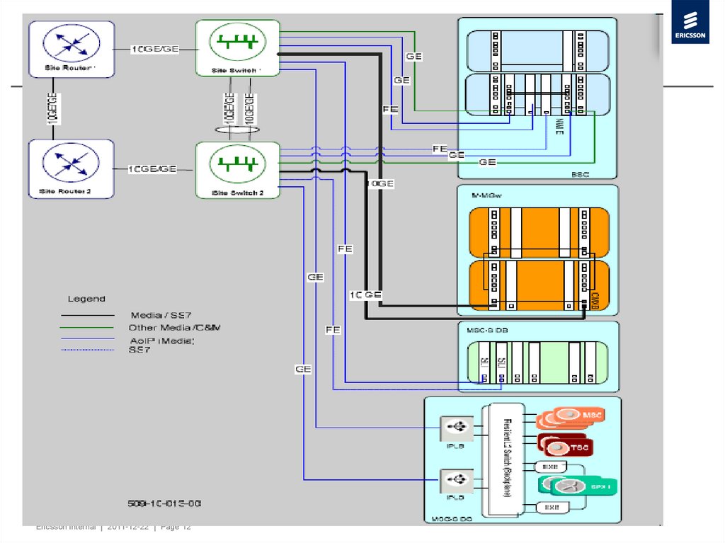
11. Physical Connectivity
› Control Plane (BSSAP Signaling)MSC-S: SLI boards
MSC-S BC: IPLB boards
BSCs transmit control signaling via their SLI boards
› User Plane
BSC: AGW, SWI-E
M-MGw: ET-MFG, ET-IPG, CMXB boards
Ericsson Internal | 2011-12-22 | Page 11
12.
Ericsson Internal | 2011-12-22 | Page 1213. BSC
Ericsson Internal | 2011-12-22 | Page 1314. Logical Connectivity
› NWI-E deployment mechanisms for BSCEricsson Internal | 2011-12-22 | Page 14
15. Logical Connectivity
› Logical View of the VLANs in the switchesEricsson Internal | 2011-12-22 | Page 15
16. Logical Connectivity
Ericsson Internal | 2011-12-22 | Page 1617. IP Addressing for AoIP traffic
› A_userplane and SR_A_userplane subnet on BSCsEricsson Internal | 2011-12-22 | Page 17
18. IP Routing Principle for AoIP Traffic
Ericsson Internal | 2011-12-22 | Page 1819. Network Topology
Ericsson Internal | 2011-12-22 | Page 1920. Dimensioning msc-s
› MSC-S & MSC-S BC› There is no impact to the MSC-S or BC due to AoIP either on control or
user plane. The control plane traffic is merely re-routed to different
SCTP associations and instead of traversing the MGW, it is routed
direct to the BSC. The impact of the additional IEs in BSSAP and the
new GCP profile is minimal.
Ericsson Internal | 2011-12-22 | Page 20
21. Dimensioning MGw
› MGW› The impact on MGWs of direct signalling between BSC and MSC is
that the MGW no longer acts as transit node for this traffic and hence
there will be a significant reduction in the GPB load as well as the node
MSUs/s handled.
› GCP processing capacity is not impacted.
› The bandwidth is derived by assuming 23Kbps per call and 80%
utilisation of the link.
Ericsson Internal | 2011-12-22 | Page 21
22. BSC Traffic
Ericsson Internal | 2011-12-22 | Page 2223. Dimensioning MGw
› With AoIP, BSCs will not be connected to a single MGW as is the casewith AoTDM. Since the BSCs will use the IP backbone network they
can connect to any MGW that is also connected to the backbone,
which is all MGWs in the network. To ensure optimum MGW selection,
the correct MGGs and route parameters must be set
› Assuming that all AoIP traffic is evenly distributed over the AoIP MGWs,
the traffic and b/w in following table can be added to the existing NboIP
traffic figures obtained from recent stats to obtain utilization forecast for
ET boards
Ericsson Internal | 2011-12-22 | Page 23
24. Dimensioning MGw
› The ETs column shows the number of ET-MFG boards forGMPv3.0 and the number of ET-IPG boards for GMPv4.0
MGWs. The AMR column shows the utilization of the ET
boards if all the traffic is AMR.
Ericsson Internal | 2011-12-22 | Page 24
25. Dimensioning MGw
› The capacity of an ET-MFG board is 20KErl/board with AMR and3.5KErl/board with PCM. Since AMR requires 23Kb/s per call, the
board capacity is 460Mb/s, leading to utilization of 31%. If all the traffic
is PCM coded (which is not possible since AoIP cannot be PCM), the
board capacity is 560Mb/s, leading to 26% utilization. In practice, the
utilization will lie between these two values, depending on how much
traffic is PCM coded.
› The capacity of an ET-IPG board is 30KErl/board for AMR and 5KErl
for PCM. These values are used for WJK19 forecast.
Ericsson Internal | 2011-12-22 | Page 25
26. Network Considerations
› MGG Design: It is optional to connect a specific MGG to BSC onMSC. If no MGG is connected then any MGG connected to the BSC
could be selected.
› Extended Unit Data Message
With AoIP the new "Reset IP resource" message will be 253 or 254
bytes long, depending on Cause value. With UDT such a long message
cannot be handled. To be able to handle long messages all concerned
Signaling Points (MSC-Ss and BSCs) must be configured to allow
XUDT, i.e. basically the handling segmented messages.
› Optional Feature
› TrFO Codec Handling
› Measurement based Admission Control (MBAC) in M-MGw
› Security for IP Transport with Traffic Separation
› Bandwidth Efficiency with IP Multiplexing
Ericsson Internal | 2011-12-22 | Page 26
27. MGG Design
› In order to achieve this optimization, new control relationships need tobe established between MSC-Ss and access MGws.
› The objectives are:
• Use only one MGW for all intra-regional MS-MS calls originating and
terminating on AoIP BSCs.
• Distribute AoIP traffic evenly over all available AoIP MGWs.
• Facilitate future use of TrFO by setting Forward Bearer Setup on all
routes.
Ericsson Internal | 2011-12-22 | Page 27
28. MGG Design
› To meet these requirements, the following actions need tobe carried out.
• Create Sigtran associations between all AoIP MSC-S and all AoIP MMGWs.
• Create v-MGWs in all AoIP MGWs for each AoIP MSC-S.
• Create a MGG consisting of all AoIP MGWs at each AoIP MSC-S
• Ensure that all BICC routes are set to FWBS
• Set parameter “ANYMGW” on all other outgoing AoIP MSC BICC
routes.
• Set parameter “ANYMGW” on all outgoing AoIP BSC routes, with the
AoIP MGWs set to Priority.
Ericsson Internal | 2011-12-22 | Page 28
29. TrFO Feature
› MSC-SNot needed
Enhanced to support AoIP
TFO/TrFO Interworking
FAJ 121 866
Transcoder Free
Operation (TrFO)
FAJ 121 528
Compressed Speech
in the Core Network
FAJ 121 529
Existing licenses can be
converted into TrFO
Feature
Ericsson Internal | 2011-12-22 | Page 29
30. TrFO Feature
› M-MGw featureNot needed
Enhanced to support AoIP
Tandem Free
Operation (TFO)
FAJ 121 939
Compressed Speech
on Nb
FAJ 121 551
Compressed Speech
on Nb
FAJ 121 551
Ericsson Internal | 2011-12-22 | Page 30
31. Call setup
DetermineMSC-PCL
Build Supported Codec List
(oSCL)
10
7
Terminate Codec
Negotiation:
build tSCL, find SC, build
ACL
3
IAM (oSCL)
4
9
APM (SC, ACL)
17
APM (connect)
oMSC
tMGw
Reserve RTP Connection Point (Pref. GERAN Codec)
Ericsson Internal | 2011-12-22 | Page 31
19
ACK (MGW Address)
Config. RTP Connection Point (BSS Add., Codec)
SC: Selected Codec
NbUP
ACK
MSC-PCL: Codec List (MSC Preferred)
16
22
ACL: Available Codec List
MS-SCL: MS Supported Codec List
Seize CN Termination
oMGw
BSS-SCL: Codec List (BSS Supported)
SCL: Supported Codec List
8
Seize CN Termination
RTP
15
13
Config. RTP Connection Point (BSS Add., Codec)
oBSC
ACK
12
14
ACK (MGW Address)
oMS 1
Reserve RTP Connection Point (Pref. GERAN Codec)
11
2
tMSC
20
5
tMS
21
RTP
tBSC
32. AoIP in Layered Architecture (MSS6.1)
Out-of-Band Transcoder Controlvia BICC
MSC
Server
MSC
Server
TrFO in Core Network
coded speech
TFO on A-interface
GSM-EFR,
FR_AMR, HR_AMR
FR_AMR-WB
GSM-FR, GSM-HR
PCM (+ TFO)
MS
UE
GSM-EFR,
FR_AMR(s1), HR_AMR(s1),
UMTS_AMR2(s1), UMTS_AMR2(s7),
UMTS_AMR(s7)
FR_AMR-WB(s0), UMTS_AMRWB(s0), PCM
Legacy
GERAN
UTRAN
A over IP
GSM-FR, GSM-HR, GSM-EFR,
FR_AMR, HR_AMR
FR_AMR-WB,
CLEARMODE
AMR, AMR-WB
MGW
MGW
via ATM or IP
T
ISDN
"TrFO"
AoIP
GERAN
MS
PCM
Legacy
GERAN
MS
PSTN
T
PCM
PCM
IMS (SIP)
AMR, EFR,
G729, PCM
Codec in Terminal
Transcoding to PCM
Ericsson Internal | 2011-12-22 | Page 32
TFO (Decoding only)
“VoIP” (SIP-I)
Wireless (SIP-I)
Softswitch
33. Measurement based Admission Control (MBAC)
› Measurement Based Admission Control (MBAC) is used formeasuring network performance in order to make
admission control decisions. The M-MGw detects
congestion by monitoring the stream of the packets.
› Congestion can be detected in three different ways:
Packet drop.
ECN (Explicit Congestion Notification) marked packets.
Packets with a re-marked DSCP (Differentiated Services
Code Point) (Applicable for MSS R5.1 onwards)
Ericsson Internal | 2011-12-22 | Page 33
34. MBAC Principle
Ericsson Internal | 2011-12-22 | Page 3435. First Way: Packet Loss
› Monitor packet loss and estimate the loss rate– Monitor RTP layer packet loss from a remote site
› By monitoring the sequence number of packets received
› Not in sequence packet loss
– Estimate the packet loss rate using Exponential Moving Average Algorithm
(weighting factor configurable)
Rnew = Llastmeasure × MBACWeightingFactor+ RlastEstimate × (100% - MBACWeightingFactor)
› If estimate rate exceeds the threshold rate set
– Block call bearer setup attempts
– Return to normal if the estimate rate is below the threshold
Ericsson Internal | 2011-12-22 | Page 35
36. MBAC CONFIGURATION
› Remote site needs to be known by the local site› MOs to be configured to achieve this
– IpNetwork MO
represents IP address numbering plan in IP core network
– RemoteSite MO --- Created Automatically
used for getting all the counters from remote sites, reflects calls reject due
to MBAC
– MgwApplication MO --- Attribute changes needed
› IpNetwork and RemoteSite MO must be defined for MBAC
to work
Ericsson Internal | 2011-12-22 | Page 36
37. MBAC Configuration
› MGwApplication– mbacMode
› Attribute to turn the feature on and off
– mbacMeasurementInterval
› How often a new packet loss estimate is calculated
› Range 1~10s (default 2s)
– mbacThreshold
› The limit for packet loss rate
› If the limit is exceeded new call attempts are rejected
› Value range from 1 to 5 (default 3) correspond to
-2
-3
-4
-5
-6
1=10 , 2=10 , 3=10 , 4=10 , 5=10
– mbacWeightingFactor
› Specifies a weight for estimation
› Value range 1~100 in percentage (default 75)
– explicitCongestionNotification
› On or off
Ericsson Internal | 2011-12-22 | Page 37
38. A-over IP Migration
39. Bearer selection for A@IP, (MSC Pool)
MSC PoolMSC-S
MSC-S
TDM
TDM
IP
TDM
BSC
TDM
TDM
BSC
IP
M-MGw
M-MGw
A-IF bearer selection (TDM or IP):
› Statically configured in MSC-S for each BSC individually
› Configured in each MSC-S separately/independently
› BSC supports both TDM and IP in parallel
Ericsson Internal | 2011-12-22 | Page 39
40. Migration possibilities
› Smooth A-over IP migration in MSC Pool environment– BSC migrated at a time with additional possibility of fine control of
traffic on affected A interface by moving subscribers within the MSC
Pool
› A-over IP migration in non-MSC Pool environment
– BSC migrated at a time by changing bearer configuration
Ericsson Internal | 2011-12-22 | Page 40
41. Smooth A-over IP migration in MSC Pool environment
› In MSC Pool environment A-IF is controlled/shared by all MSC poolmembers (all MSC-Ss).
› It’s possible to control traffic portion on A-IF in a BSC by controlling
number of subscriber in the MSC-S(s) which contribute to the traffic on
that particular A-IF.
› Smooth A-over IP migration idea is based on following steps (illustrated
in next slides):
– Starting with one BSC and one MSC-S, the A-IF traffic portion is reduced by
moving subscribers handled by the BSC and registered in the MSC-S
towards other MSC Pool members.
– A-over IP is configured and activated in the MSC-Ss with no (or very low
traffic) since there are no (or few) subscribers registered in the MSC-S
which contribute to the A-IF traffic on that particular BSC.
– Traffic can be rump-up by moving subscribers back to the MSC-S.
– Process is repeated for all MSC-Ss in the pool.
– Process is repeated for all BSCs in the pool.
Ericsson Internal | 2011-12-22 | Page 41
42. Smooth A-over IP migration (A)
MSC Pool………………
MSC-S
MSC-S
IP Transport
………….
M-MGw
M-MGw
TDM
TDM
TDM
BSC
› Initial network, A-over TDM
Ericsson Internal | 2011-12-22 | Page 42
TDM
……………
BSC
43. Smooth A-over IP migration (B)
1MSC Pool
………………
MSC-S
MSC-S
IP Transport
………….
M-MGw
M-MGw
IP
IP
TDM
1
TDM
BSC
TDM
……………
BSC
› First BSC upgraded for A-over IP (physical connectivity, configuration)
› Configuration for A over IP prepared in the first MSC-S (not activated yet)
› Subscribers (or part of them) originally handled by the BSC and registered in the first
MSC-Ss moved to other MSC-Ss (in order to limit traffic on new A-over IP IF)
› A-over IP activated in first MSC-S, test calls
› A-over IP traffic rump-up by moving subscribers back to the first MSC-S
› Remaining MSC-Ss still run A-over TDM towards first BSC
Ericsson Internal | 2011-12-22 | Page 43
44. Smooth A-over IP migration (C)
MSC Pool………………
MSC-S
MSC-S
IP Transport
………….
M-MGw
M-MGw
IP
IP
TDM
1
IP
BSC
TDM
……………
BSC
› Process repeated until all MSC-Ss are configured for A over IP towards first BSC
› After this first BSC migration completed, all traffic runs A-over IP
Ericsson Internal | 2011-12-22 | Page 44
45. Smooth A-over IP migration (D)
MSC Pool………………
MSC-S
MSC-S
IP Transport
………….
M-MGw
M-MGw
IP
IP
IP
BSC
IP
……………
› Migration process repeated for all BSCs
› Finally, all traffic runs A-over IP
Ericsson Internal | 2011-12-22 | Page 45
IP
IP
BSC
46. A-over IP migration in non-MSC Pool environment
› BSCs controlled by one MSC-S are one by one migratedtowards A-over IP
› Process repeated for all MSC-Ss
Ericsson Internal | 2011-12-22 | Page 46
47. A-over IP migration in non-MSC Pool environment (A)
………………MSC-S
MSC-S
IP Transport
………….
M-MGw
M-MGw
TDM
TDM
BSC
› Initial network, A-over TDM
Ericsson Internal | 2011-12-22 | Page 47
BSC
TDM
…………
BSC
48. A-over IP migration in non-MSC Pool environment (B)
………………1
MSC-S
MSC-S
IP Transport
………….
M-MGw
M-MGw
IP
TDM
IP
1
BSC
TDM
BSC
…………
BSC
› First BSC controlled by the first MSC-S migrated towards A-over IP
– BSC connected to IP infrastructure
– Configuration done in the BSC and the MSC-S
– A-over IP activated for the BSC
Ericsson Internal | 2011-12-22 | Page 48
49. A-over IP migration in non-MSC Pool environment (C)
………………1
MSC-S
MSC-S
IP Transport
………….
M-MGw
M-MGw
IP
IP
IP
BSC
TDM
IP
BSC
…………
BSC
› All BSCs under control of the first MSC-S migrated to A-over IP
Ericsson Internal | 2011-12-22 | Page 49
50. A-over IP migration in non-MSC Pool environment (C)
………………MSC-S
MSC-S
IP Transport
………….
M-MGw
M-MGw
IP
IP
IP
IP
BSC
BSC
…………
BSC
› A-over IP migration completed in all MSC-Ss and all MSCs
Ericsson Internal | 2011-12-22 | Page 50
51. Possible A-over IP network deployment models
Scenario 1:MSS expansion with A-over IP
› Capacity added into network (or
moved from Monolythic part) by
deployment of GSM with A-over IP
› Coexistence of A-over IP and A-over
TDM in the network
› Benefits from A-over IP also in part of
the network not migrated yet (e.g.
optimal MGW selection for MS-MS
calls between A-over TDM and Aover IP)
Ericsson Internal | 2011-12-22 | Page 51
Scenario 2:
Migration from A-over TDM towards
A-over IP in MSS network
› Relacement of A-over TDM by A
over IP
› Replacment can be done in steps,
e.g. smooth A-over IP migration
using smooth migration procedure
52. MSS expansion with A-over IP
MSC-SMSC-S
MSC-S
MSC-S
MSC-S
MSC-S
MSC-S
MSC-S
IP Transport
MSC-S
MSC-S
MSC-S
MSC-S
IP Transport
M-MGw
M-MGw
M-MGw
M-MGw
BSC
M-MGw
M-MGw
M-MGw
M-MGw
M-MGw
M-MGw
M-MGw
M-MGw
BSC
TDM
TDM
MSC
MSC
MSC
BSC
BSC
BSC
TDM
BSC
BSC
BSC
BSC
Optional: Monolithic network
Ericsson Internal | 2011-12-22 | Page 52
BSC
BSC
BSC
BSC
BSC
BSC
53. Migration from A-over TDM towards A-over IP in MSS network
MSC-SMSC-S
MSC-S
MSC-S
MSC-S
MSC-S
MSC-S
MSC-S
IP Transport
M-MGw
M-MGw
M-MGw
M-MGw
IP Transport
M-MGw
M-MGw
M-MGw
M-MGw
TDM
BSC
BSC
BSC
BSC
BSC
BSC
Ericsson Internal | 2011-12-22 | Page 53
BSC
BSC
54. Structure of the Migration Procedure
1. Check Baseline Phase(ensure well defined starting point for migration)
2. Preparation phase
(actions before taking ’AoIP’ into service)
3. Activation phase
(take ’AoIP’ into service: admin. Change in MSC-S)
4. Clean-up Phase
(remove dispensable HW and configuration)
› From A-interface user plane of IP, Method of Procedure
Ericsson Internal | 2011-12-22 | Page 54
55. Check Baseline Phase
› Site infrastructure: check if IP transmissions over GE links between all applicableBSCs and site switches are operational
› BSC:
- BSC Health Check should be performed (print various status data)
- Consistency Check performed, analyzed and fixed (e.g. A1 and A2 alarm)
- CP backups made for all applicable BSCs
› MSC-S:
- MSC-S Health Check should be performed (print various status data)
- Consistency Check performed, analyzed and fixed (e.g. A1 and A2 alarm)
- STS data (Authentication, Call Success Rate, Location Update, Traffic on
Routes counters or Size Alterations) must be collected. This data will be used
for comparison and analysis after AoIP has been activated
Ericsson Internal | 2011-12-22 | Page 55
56. Preparation Phase
› Site infrastructure:- Configure Media_CS and Media_CS_BSC VLANs on Site Switches
- Configure Media_CS and Media_CS_BSC VLANs on Site Routers
- Configure IP addresses and Routing on Site Routers
› M-MGw:
- define additional MGCs (vMGWs) if wanted
- activate GCP profile EP7
- AoIP specific parameter settings (CSD service, Jitter Handling service,
RTCP)
- MBAC configuration (modify attributes of MO MgwApplication)
Ericsson Internal | 2011-12-22 | Page 56
57. Preparation Phase (Continued)
BSC:- Configure NWI-E switches (adapt parameter file template -> Python
script)
- change XUDT capability of Signaling points (C7NPC)
- connect AGW (connect to SNT, define IP addresses of AGW boards)
- define IP address for AoIP application
- AoIP config. Data (DSCP, Jitter Buffer Size, Multiplexing parameters)
- Activate AoIP in the BSC (RRAIP)
- check IP connectivity over the backbone (ping the AoIP application
address)
MSC-S:
- change XUDT capability of Signaling points (C7NPC)
Ericsson Internal | 2011-12-22 | Page 57
58. Activation Phase
› MSC-S:- Definition of a Media Gateway (MG) and Media Gateway Group
(MGG) on
MSC (NRGGI - optional with AoIP)
- Connect AoIP BSC or Configure AoTDM BSC with AoIP capability
(define AoIP route pair WITH DETY MAIPCM – EXROI/MGBSI)
- Activate RTCP capability on AoIP BSC
(MGBSC)
- Configure the MGG for AoIP BSC
(EXRBC - optional with AoIP)
- Configure the Preferred Bearer Set Up direction for AoIP BSC
(EXRBC – FWD set-up is recommended)
- Remove the IP restriction on traffic
(MGRTC)
BSC: (only for new BSC with no TDM connectivity)
- from now on allow traffic to/from applicable MSCs (RLTDC)
Ericsson Internal | 2011-12-22 | Page 58
59. Clean-up Phase
› Site infrastructure:- Remove un-used TDM connections between BSCs and Site Switches
› M-MGw:
- Remove un-used HW (un-used TDM connections and ET-C41 boards)
› BSC:
- Remove un-used HW
› MSC-S:
- Delete the definition of a BSC for TDM A-interface in the MSC-S
(MGBSE)
Ericsson Internal | 2011-12-22 | Page 59
60. Configuration in MSC
› Definition of SP and SCCP level configuration (if not).› M3UA and SCTP related configuration for Signaling traffic (if not).
› Activate the A-Interface over IP feature in MSC:
– SYPAC:ACCESS=ENABLED,PSW=PSW2PAR;
– DBTRI;
– DBTSC:TAB=AXEPARS,SETNAME=GSMMSCF, NAME=AOVERIPAVAILF,VALUE=1;
– DBTRE:COM;
› Increase the Size Alteration File for block MAIPCM with SAE 500:
– SAAII:SAE=500,BLOCK=MAIPCM,NI=200;
› Define the route pair (incoming and outgoing) representing the A over IP connection
capability of the new BSC:
– EXROI:R=IBSC84O&IBSC84I,DETY=MAIPCM,FNC=3,SI=SCCP,SP=3-6084;
Ericsson Internal | 2011-12-22 | Page 60
61. Configuration in MSC
› Define the AoIP BSC and connect it with the incoming and outgoing routesrepresenting the AoIP capability of the BSC:
– MGBSI:BSC=BSC84, R1=IBSC84O,R2=IBSC84I;
› Define the Media Gateway Group for AoIP BSC and configure the preferred bearer
setup direction:
– EXRBC:R=IBSC84O ,RGSPAR=MGG-WFBSC84;
– EXRBC:R=IBSC84I ,RGSPAR=PBSD-FORWD;
› Configure parameters for the AoIP BSC using “BSCDATA” and “BSCCCODEC”
parameter in command MGBSC. For example:
– MGBSC:BSC=BSC84,BSCDATA=HRATE-1; !SUPPORT HALF RATE FUNCTION!
– MGBSC:BSC=BSC84,BSCDATA=NIRR-1;
– MGBSC:BSC=BSC84,BSCDATA=MSCODER-1;
– MGBSC:BSC=BSC84,BSCDATA=PHASE2-1;
– MGBSC:BSC=BSC84,BSCDATA=MSLOT-4; !4 CHANNEL MULTISLOT!
– MGBSC:BSC=BSC84,BSCDATA=14DOT4-1; !14.4 TRAFFIC ALLOWED!
– MGBSC:BSC=BSC84,BSCCODEC=FR_AMR_GC; !FR_AMR Set 1!
– MGBSC:BSC=BSC84,BSCCODEC=HR_AMR_GC; !HR_AMR Set 1!
– MGBSC:BSC=BSC84,BSCCODEC=GSM_EFR;
Ericsson Internal | 2011-12-22 | Page 61
62. Configuration in MSC
› Define the LAI and CELLs for the AoIP BSC (if not).› To enable the OOBTC availability in MSC (if not):
– DBTRI;
– DBTSC:TAB=AXEPARS,SETNAME=GSMMSCF,NAME=OOBTCAVAIL,VALUE=1;
– DBTRE:COM;
› To activate the OOBTC feature in MSC (if not):
– DBTRI;
– DBTSC:TAB=AXEPARS,SETNAME=GSMMSCC,NAME=OOBTCACT,VALUE=1;
– DBTRE:COM;
› To enable the supported Codecs for Nb-interface (if not):
– DBTRI;
– DBTSC:TAB=AXEPARS,SETNAME=AXENODECODECC,NAME=PROPERTY11,VALUE=7;
– DBTSC:TAB=AXEPARS,SETNAME=AXENODECODECC,NAME=PROPERTY12,VALUE=7;
– DBTSC:TAB=AXEPARS,SETNAME=AXENODECODECC,NAME=PROPERTY13,VALUE=7;
– ……
– DBTRE:COM;
Ericsson Internal | 2011-12-22 | Page 62
63. Configuration in MSC
› Remove the IP Restriction on traffic:– MGRTC:R1=IBSC84O,R2=IBSC84I,AOIPRESTR=OFF;
›
By default, as soon as the IP route pair is defined by route administration procedures,
the IP restriction on traffic is indicating ’ON’ which means that no IP traffic is allowed to
be served.
› To check the restriction status of a specific AoIP traffic route pair, use command
“MGRTP”:
– MGRTP:R1=IBSC84O,R2=IBSC84I;
Ericsson Internal | 2011-12-22 | Page 63
64. Configuration in BSC
› Define BSSAP over IP just as MSC:– IHCOI IHRDI IHBII IHADI M3RSI
› Define AGW:
– RRGWC RRIPI RRAPI
Ericsson Internal | 2011-12-22 | Page 64
65. Reference Network
› Physical connectivity of example network before migrationSite 1
Site 2
FE
BSC 1_2
FE
BSC 1_1
BSC 2_1
SGw
GE
or
10GE
SGw
STP
IP
TSC
VLR
FE
G-MSC
MSC-S 1_1
GE
or
10GE
TSC
n x GE
or 10GE M-MGW 1_1
GE
or
10GE
VLR
SW 1_1
GE or
10GE
GE or 10GE
FE
G-MSC
MSC-S 2_1
n x GE
or 10GE
SW 1_2
SW 2_1
GE or 10GE
GE or 10GE
TDM link
Fast Ethernet link
1, n, 10 Gigabit Ethernet link
Ericsson Internal | 2011-12-22 | Page 65
GE or
10GE
GE
or
10GE
SW 2_2
GE or 10GE
GE or
10GE
GE or
10GE
SR 1_1
IP
M-MGW 2_1
n x GE
or 10GE
n x GE
or 10GE
STP
SR 2_1
SR 1_2
MPBN
Backbone
SR 2_2
66. Reference Network
› Physical connectivity of example network after migrationSite 1
Site 2
FE
BSC 1_2
GE
FE
BSC 1_1
BSC 2_1
SGw
GE
or
10GE
SGw
STP
FE
TSC
IP
VLR
G-MSC
GE
MSC-S 1_1
GE
or
10GE
TSC
n x GE
or 10GE M-MGW 1_1
GE
or
10GE
FE
STP
IP
M-MGW 2_1
VLR
G-MSC
n x GE
or 10GE
MSC-S 2_1
GE
GE
or
10GE
n x GE
or 10GE
n x GE
or 10GE
SW 1_1
GE or
10GE
GE or 10GE
SW 1_2
SW 2_1
GE or 10GE
GE or 10GE
Fast Ethernet link
1, n, 10 Gigabit Ethernet link
Ericsson Internal | 2011-12-22 | Page 66
SW 2_2
GE or 10GE
GE or
10GE
GE or
10GE
SR 1_1
GE or
10GE
SR 2_1
SR 1_2
MPBN
Backbone
SR 2_2
GE
67. Example Network DT and Scripts
DT ScopeAoIP activation in MSC-S
Scope
BSC preparation (AXE DT)
BSC preparation
(NWI-E switch configuration)
DT File
DT file for MSC-S 1_1/2:
DT File / script
DT file for BSC1_1:
Parameter file for BSC1_1:
parameter_file_template.txt
BSC_NWI-E_configuration.py
Ericsson Internal | 2011-12-22 | Page 67