
 informatics
Similar presentations:

")
")

")

")
")


Modeling with UML
1.
Modeling with UML1
2.
Overview: modeling with UMLWhat is modeling?
What is UML?
Use case diagrams
Class diagrams
Later
Sequence diagrams
Activity diagrams
2
3.
What is modeling?Modeling consists of building an abstraction of reality.
Abstractions are simplifications because:
They ignore irrelevant details and
They only represent the relevant details.
What is relevant or irrelevant depends on the purpose of the
model.
3
4.
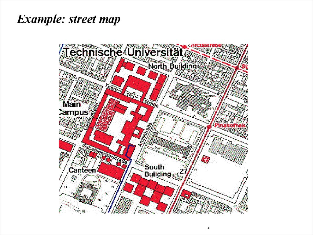
Example: street map4
5.
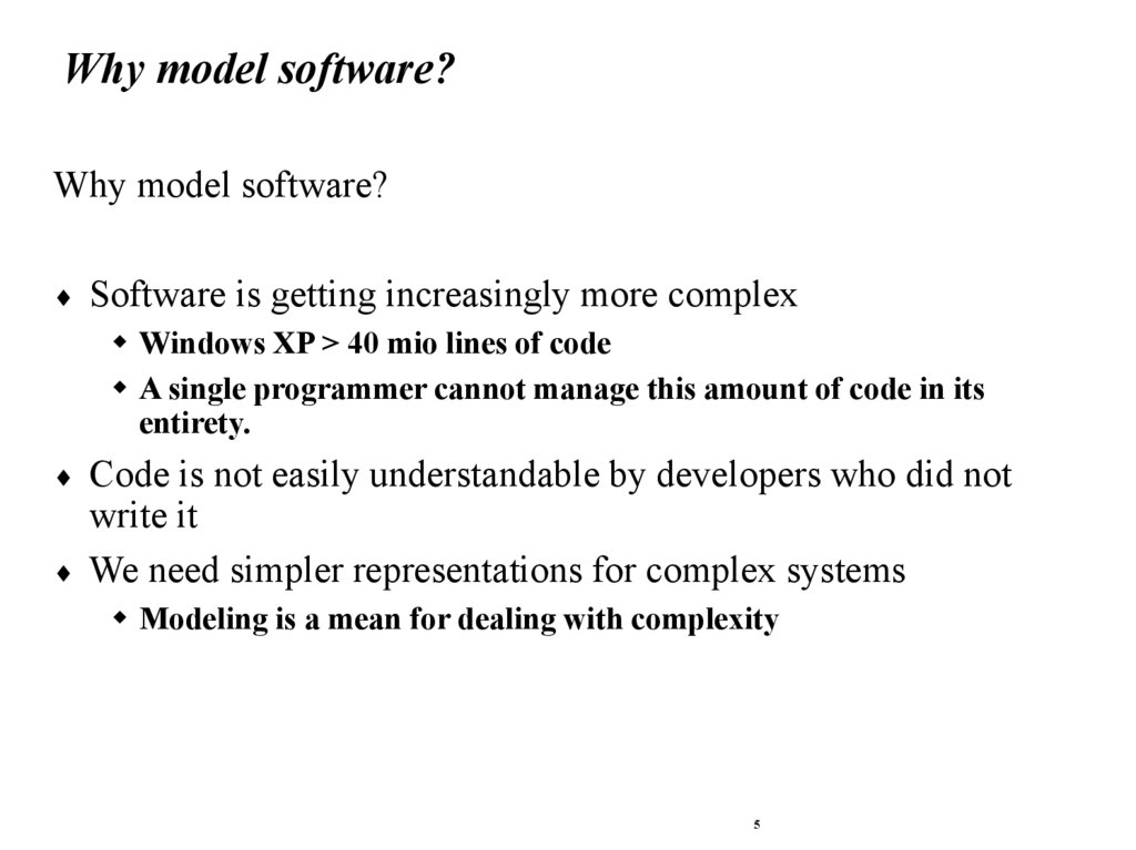
Why model software?Why model software?
Software is getting increasingly more complex
Windows XP > 40 mio lines of code
A single programmer cannot manage this amount of code in its
entirety.
Code is not easily understandable by developers who did not
write it
We need simpler representations for complex systems
Modeling is a mean for dealing with complexity
5
6.
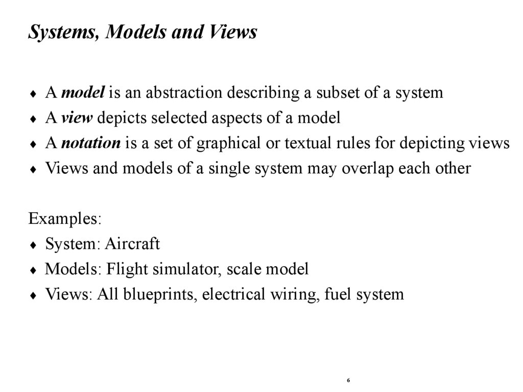
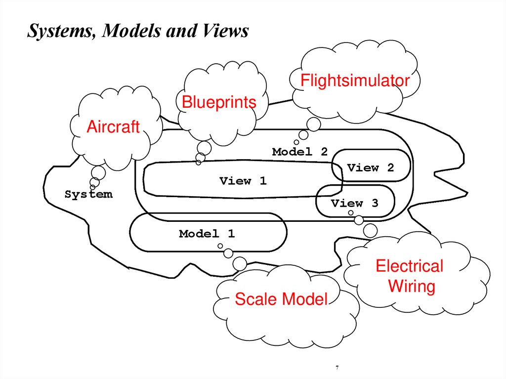
Systems, Models and ViewsA model is an abstraction describing a subset of a system
A view depicts selected aspects of a model
A notation is a set of graphical or textual rules for depicting views
Views and models of a single system may overlap each other
Examples:
System: Aircraft
Models: Flight simulator, scale model
Views: All blueprints, electrical wiring, fuel system
6
7.
Systems, Models and ViewsFlightsimulator
Blueprints
Aircraft
Model 2
System
View 2
View 1
View 3
Model 1
Electrical
Wiring
Scale Model
7
8.
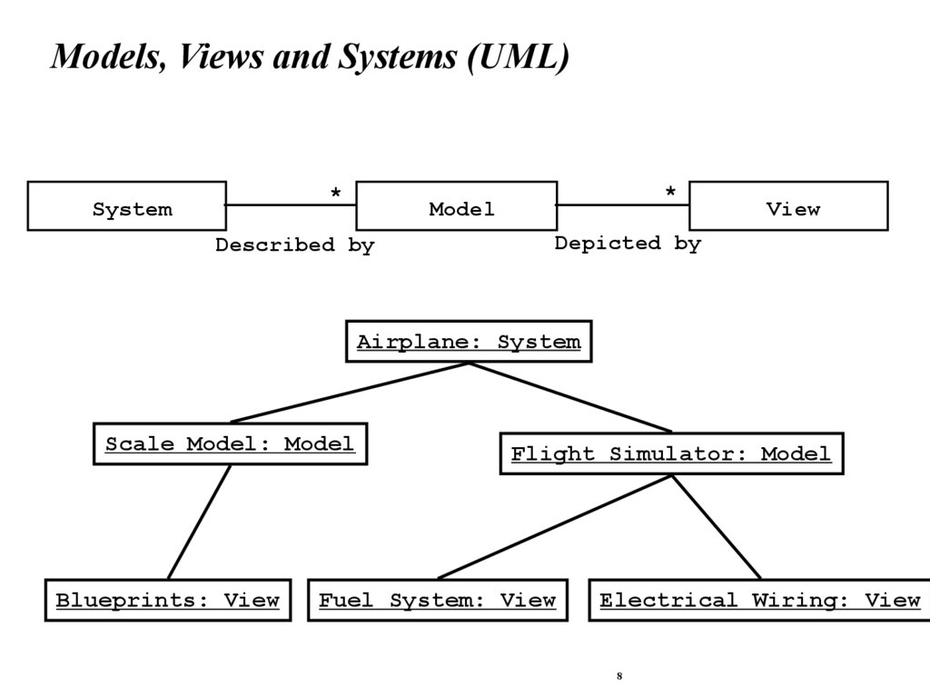
Models, Views and Systems (UML)*
System
*
Model
Described by
View
Depicted by
Airplane: System
Scale Model: Model
Blueprints: View
Flight Simulator: Model
Fuel System: View
Electrical Wiring: View
8
9.
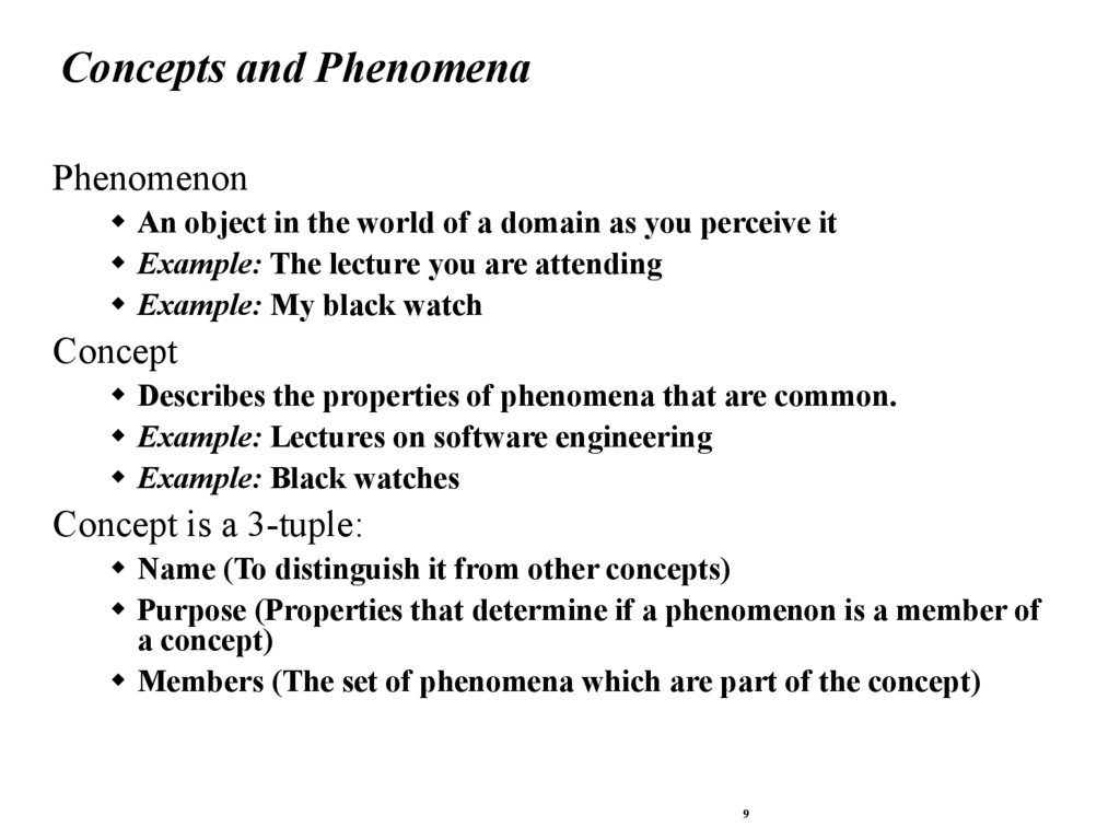
Concepts and PhenomenaPhenomenon
An object in the world of a domain as you perceive it
Example: The lecture you are attending
Example: My black watch
Concept
Describes the properties of phenomena that are common.
Example: Lectures on software engineering
Example: Black watches
Concept is a 3-tuple:
Name (To distinguish it from other concepts)
Purpose (Properties that determine if a phenomenon is a member of
a concept)
Members (The set of phenomena which are part of the concept)
9
10.
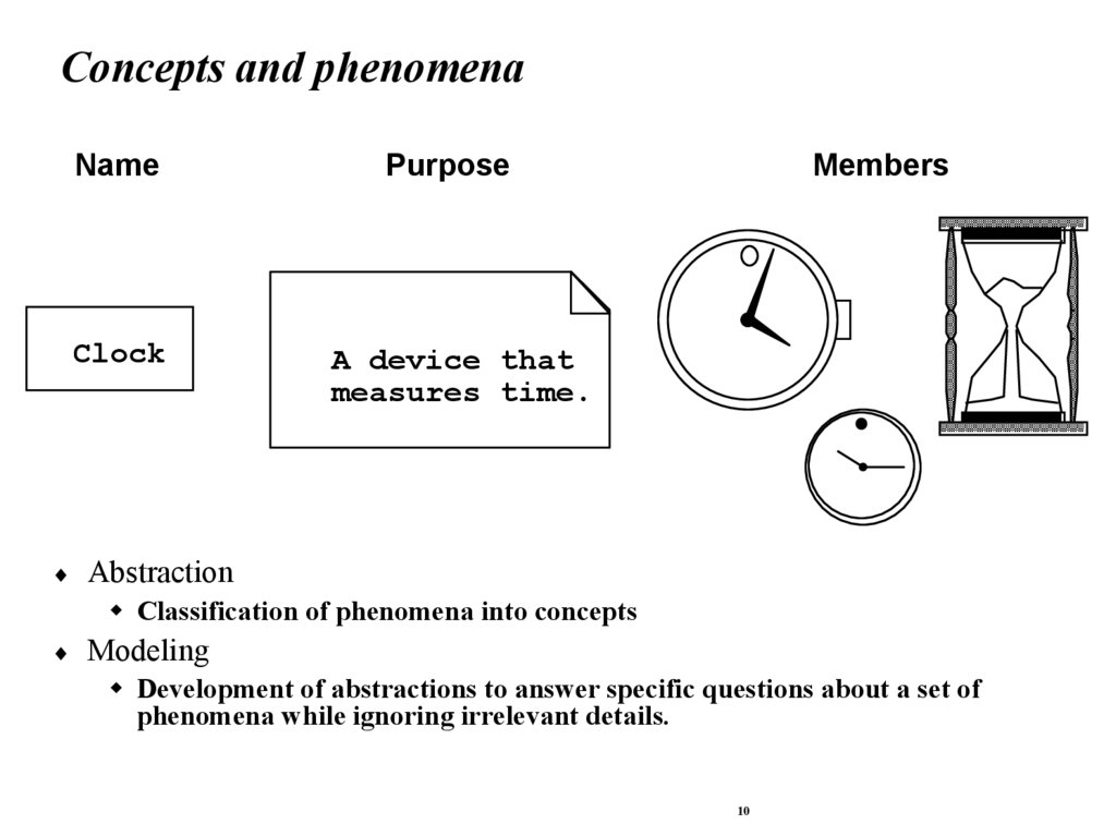
Concepts and phenomenaName
Purpose
Clock
A device that
measures time.
Members
Abstraction
Classification of phenomena into concepts
Modeling
Development of abstractions to answer specific questions about a set of
phenomena while ignoring irrelevant details.
10
11.
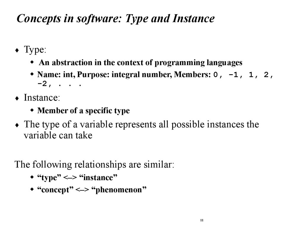
Concepts in software: Type and InstanceType:
An abstraction in the context of programming languages
Name: int, Purpose: integral number, Members: 0, -1, 1, 2,
-2, . . .
Instance:
Member of a specific type
The type of a variable represents all possible instances the
variable can take
The following relationships are similar:
“type” <–> “instance”
“concept” <–> “phenomenon”
11
12.
Abstract Data Types & ClassesAbstract data type
Special type whose implementation is hidden
from the rest of the system.
Watch
time
date
Class:
An abstraction in the context of objectoriented languages
SetDate(d)
Like an abstract data type, a class
encapsulates both state (variables) and
behavior (methods)
Class Vector
CalculatorWatch
Unlike abstract data types, classes can be
calculatorState
defined in terms of other classes using
inheritance
EnterCalcMode()
InputNumber(n)
12
13.
Application and Solution DomainApplication Domain (Requirements Analysis):
The environment in which the system is operating
Solution Domain (System Design, Object Design):
The available technologies to build the system
13
14.
Object-oriented modelingApplication Domain
Application Domain Model
UML Package
TrafficControl
Aircraft
SummaryDisplay
TrafficController
FlightPlan
Solution Domain
System Model
MapDisplay
FlightPlanDatabase
Airport
TrafficControl
14
15.
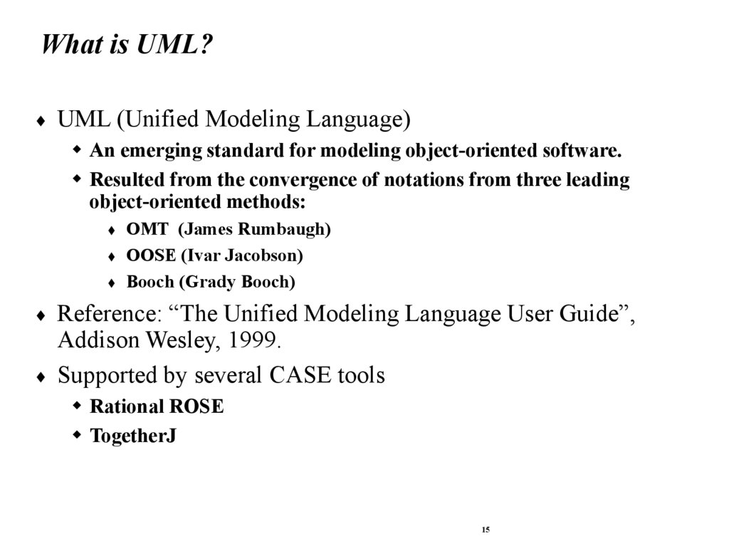
What is UML?UML (Unified Modeling Language)
An emerging standard for modeling object-oriented software.
Resulted from the convergence of notations from three leading
object-oriented methods:
OMT (James Rumbaugh)
OOSE (Ivar Jacobson)
Booch (Grady Booch)
Reference: “The Unified Modeling Language User Guide”,
Addison Wesley, 1999.
Supported by several CASE tools
Rational ROSE
TogetherJ
15
16.
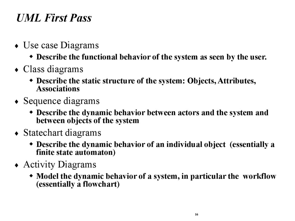
UML First PassUse case Diagrams
Describe the functional behavior of the system as seen by the user.
Class diagrams
Describe the static structure of the system: Objects, Attributes,
Associations
Sequence diagrams
Describe the dynamic behavior between actors and the system and
between objects of the system
Statechart diagrams
Describe the dynamic behavior of an individual object (essentially a
finite state automaton)
Activity Diagrams
Model the dynamic behavior of a system, in particular the workflow
(essentially a flowchart)
16
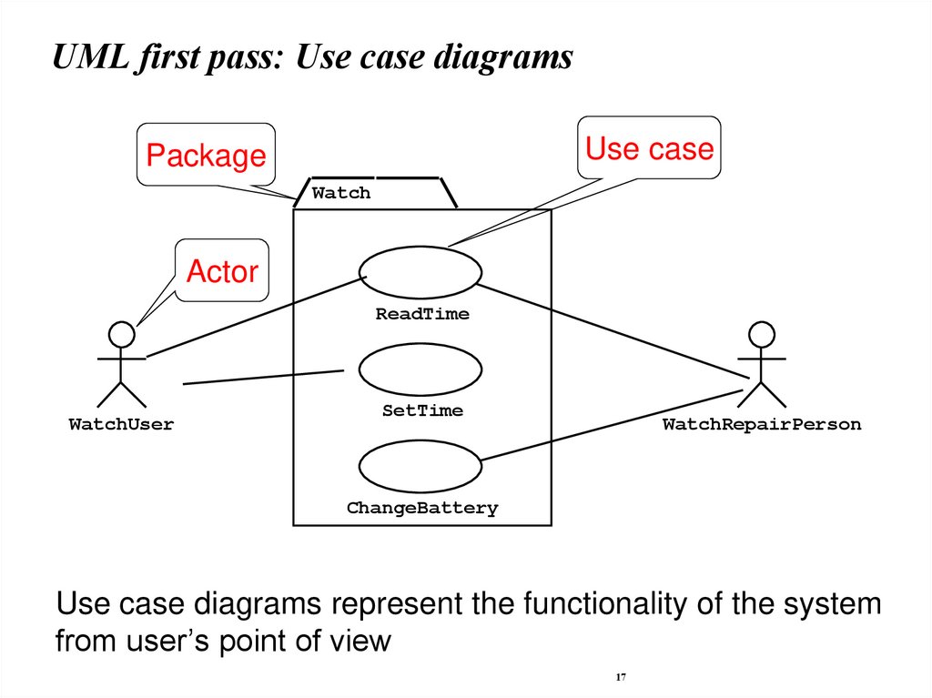
17.
UML first pass: Use case diagramsUse case
Package
Watch
Actor
ReadTime
WatchUser
SetTime
WatchRepairPerson
ChangeBattery
Use case diagrams represent the functionality of the system
from user’s point of view
17
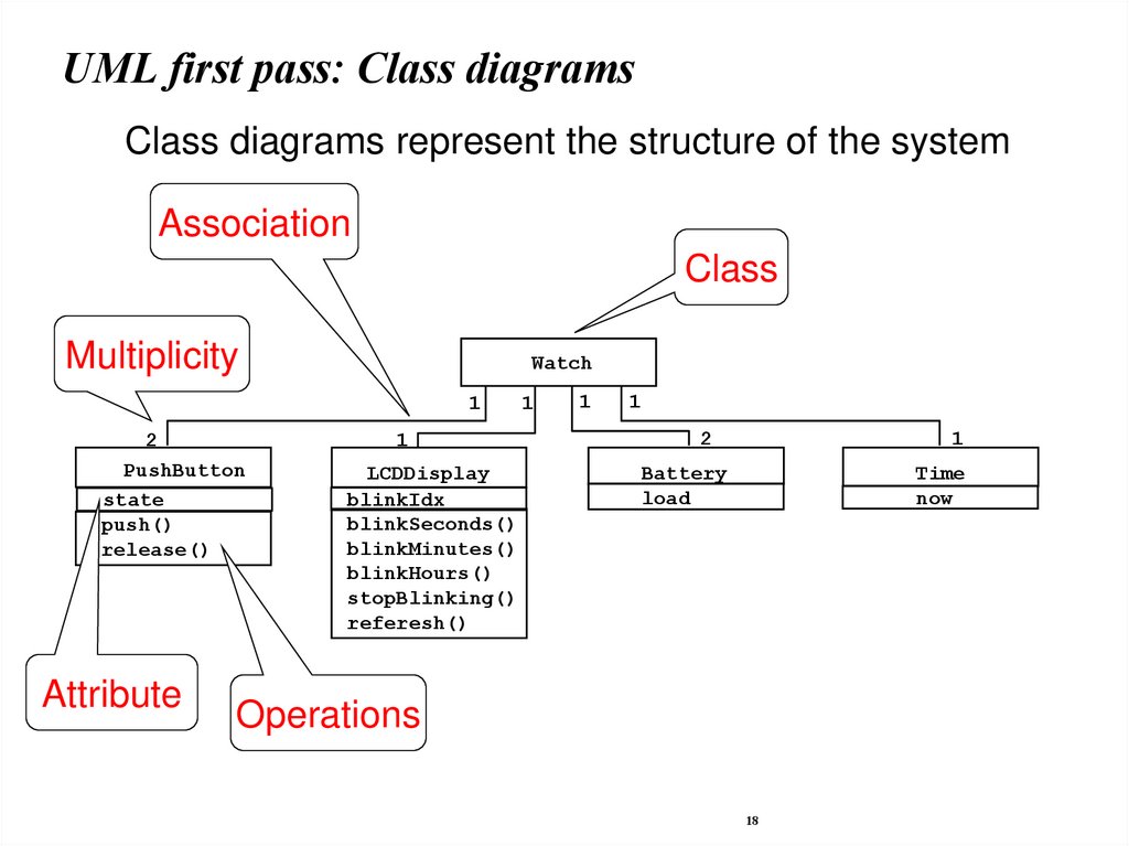
18.
UML first pass: Class diagramsClass diagrams represent the structure of the system
Association
Class
Multiplicity
Watch
1
2
PushButton
state
push()
release()
Attribute
1
LCDDisplay
blinkIdx
blinkSeconds()
blinkMinutes()
blinkHours()
stopBlinking()
referesh()
1
1
1
2
1
Battery
load
Time
now
Operations
18
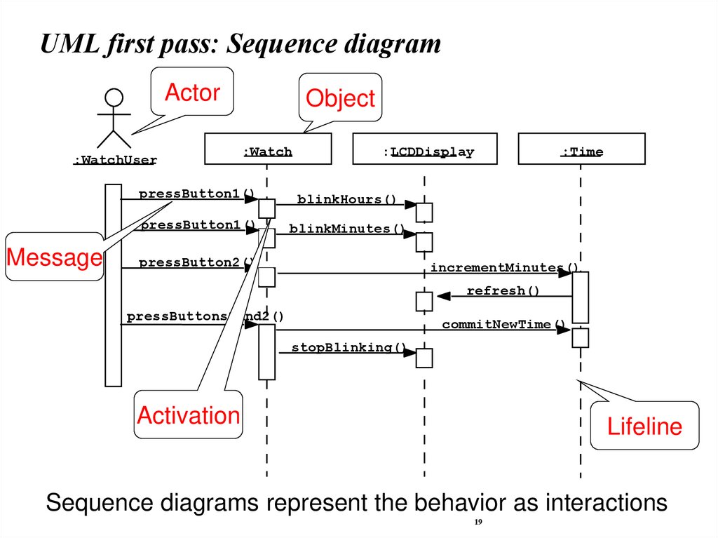
19.
UML first pass: Sequence diagramActor
:WatchUser
Message
Object
:Watch
:LCDDisplay
pressButton1()
blinkHours()
pressButton1()
blinkMinutes()
pressButton2()
:Time
incrementMinutes()
refresh()
pressButtons1And2()
commitNewTime()
stopBlinking()
Activation
Lifeline
Sequence diagrams represent the behavior as interactions
19
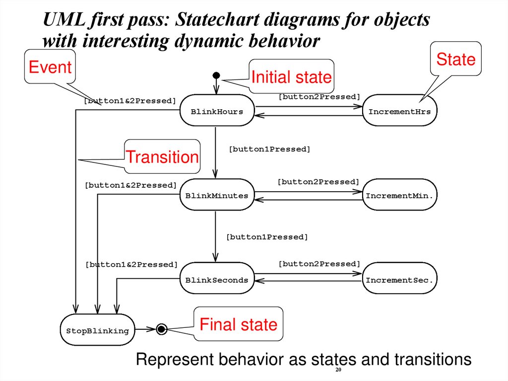
20.
UML first pass: Statechart diagrams for objectswith interesting dynamic behavior
State
Event
Initial state
[button2Pressed]
[button1&2Pressed]
BlinkHours
Transition
IncrementHrs
[button1Pressed]
[button2Pressed]
[button1&2Pressed]
BlinkMinutes
IncrementMin.
[button1Pressed]
[button2Pressed]
[button1&2Pressed]
BlinkSeconds
StopBlinking
IncrementSec.
Final state
Represent behavior as states and transitions
20
21.
Other UML NotationsUML provide other notations that we will be introduced in
subsequent lectures, as needed.
Implementation diagrams
Component diagrams
Deployment diagrams
Introduced in lecture on System Design
Object constraint language
Introduced in lecture on Object Design
21
22.
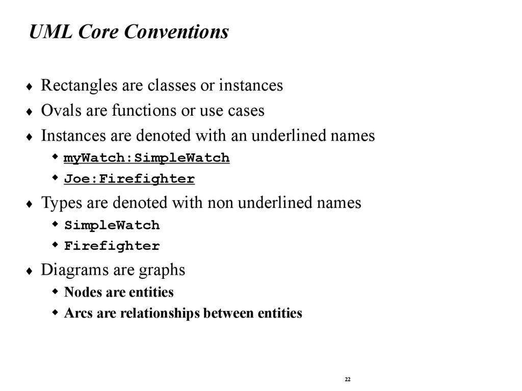
UML Core ConventionsRectangles are classes or instances
Ovals are functions or use cases
Instances are denoted with an underlined names
myWatch:SimpleWatch
Joe:Firefighter
Types are denoted with non underlined names
SimpleWatch
Firefighter
Diagrams are graphs
Nodes are entities
Arcs are relationships between entities
22
23.
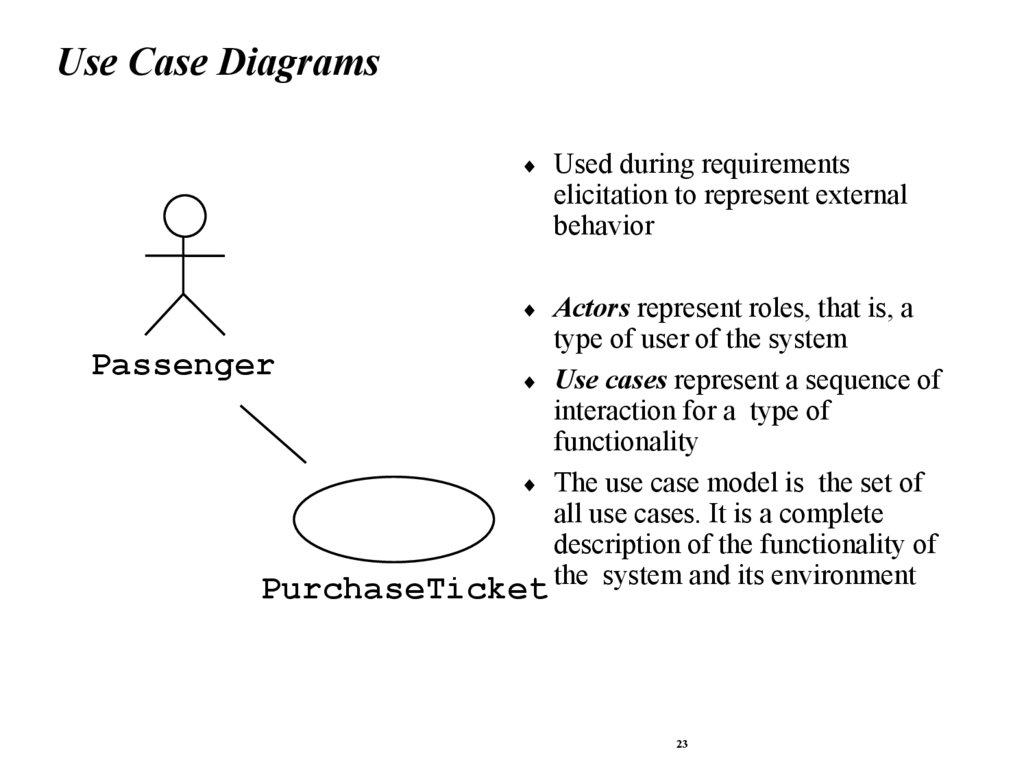
Use Case DiagramsUsed during requirements
elicitation to represent external
behavior
Actors represent roles, that is, a
type of user of the system
Passenger
Use cases represent a sequence of
interaction for a type of
functionality
The use case model is the set of
all use cases. It is a complete
description of the functionality of
PurchaseTicket the system and its environment
23
24.
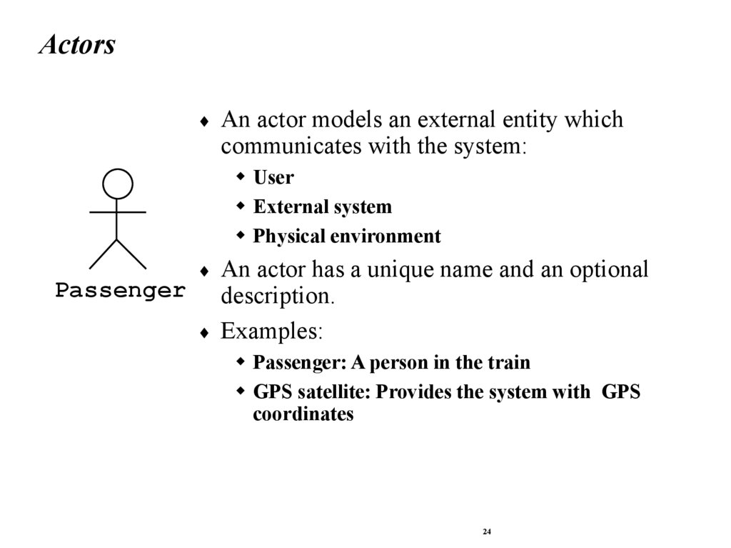
ActorsAn actor models an external entity which
communicates with the system:
User
External system
Physical environment
Passenger
An actor has a unique name and an optional
description.
Examples:
Passenger: A person in the train
GPS satellite: Provides the system with GPS
coordinates
24
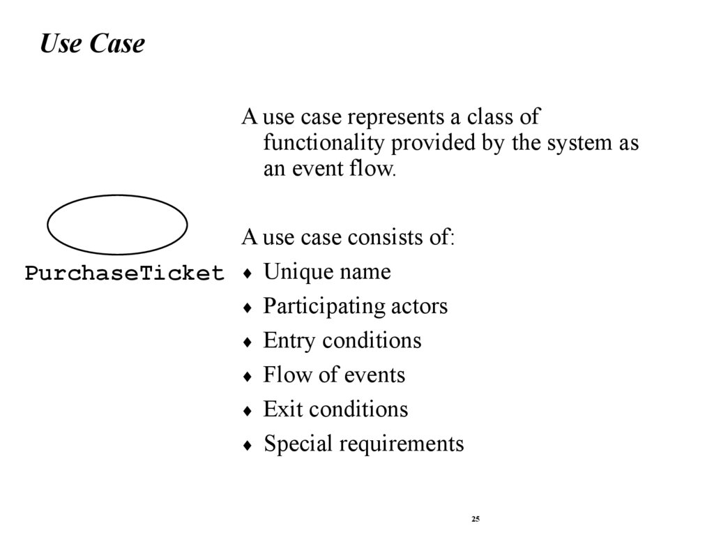
25.
Use CaseA use case represents a class of
functionality provided by the system as
an event flow.
A use case consists of:
PurchaseTicket Unique name
Participating actors
Entry conditions
Flow of events
Exit conditions
Special requirements
25
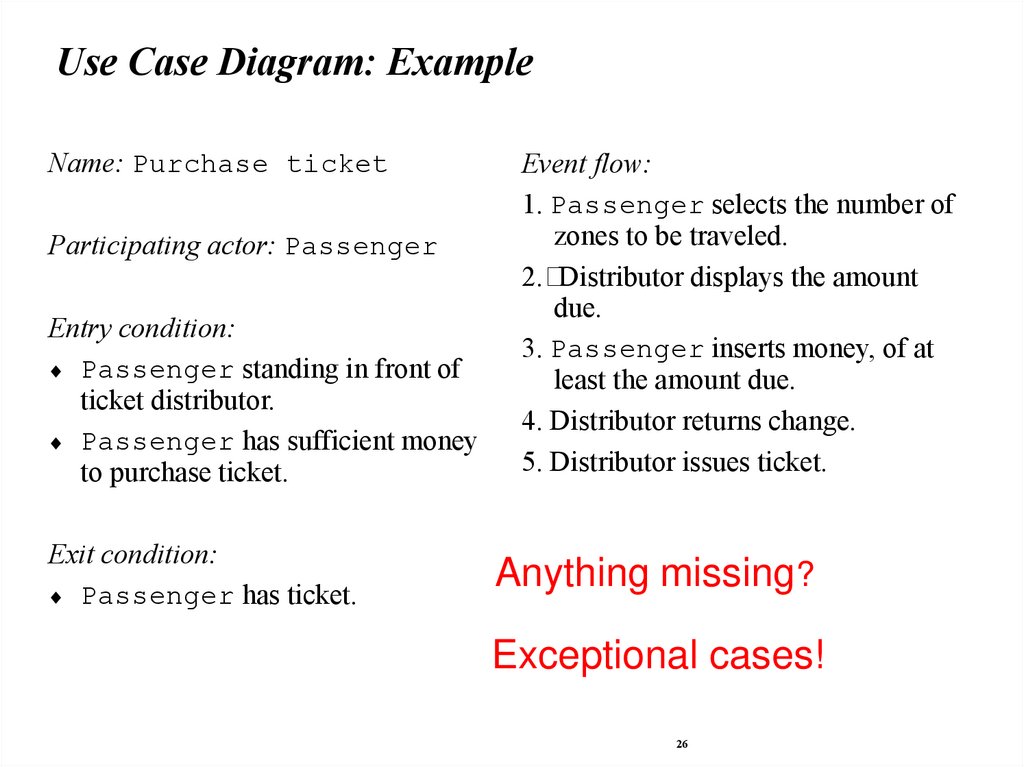
26.
Use Case Diagram: ExampleName: Purchase ticket
Participating actor: Passenger
Entry condition:
Passenger standing in front of
ticket distributor.
Passenger has sufficient money
to purchase ticket.
Exit condition:
Passenger has ticket.
Event flow:
1. Passenger selects the number of
zones to be traveled.
2. Distributor displays the amount
due.
3. Passenger inserts money, of at
least the amount due.
4. Distributor returns change.
5. Distributor issues ticket.
Anything missing?
Exceptional cases!
26
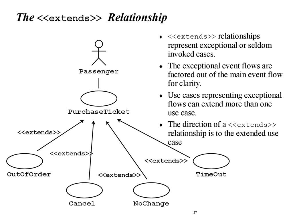
27.
The <<extends>> Relationship<<extends>> relationships
represent exceptional or seldom
invoked cases.
The exceptional event flows are
factored out of the main event flow
for clarity.
Use cases representing exceptional
flows can extend more than one
use case.
The direction of a <<extends>>
relationship is to the extended use
case
Passenger
PurchaseTicket
<<extends>>
<<extends>>
<<extends>>
OutOfOrder
<<extends>>
Cancel
TimeOut
NoChange
27
28.
The <<includes>> Relationship<<includes>> relationship
represents behavior that is factored
out of the use case.
Passenger
<<includes>> behavior is
factored out for reuse, not because
PurchaseMultiCard
it is an exception.
The direction of a <<includes>>
PurchaseSingleTicket
relationship is to the using use case
<<includes>>
(unlike <<extends>>
<<includes>>
relationships).
<<extends>>
NoChange
CollectMoney
<<extends>>
Cancel
28
29.
Use Case Diagrams: SummaryUse case diagrams represent external behavior
Use case diagrams are useful as an index into the use cases
Use case descriptions provide meat of model, not the use case
diagrams.
All use cases need to be described for the model to be useful.
29
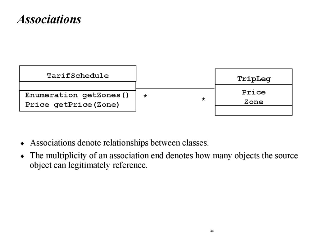
30.
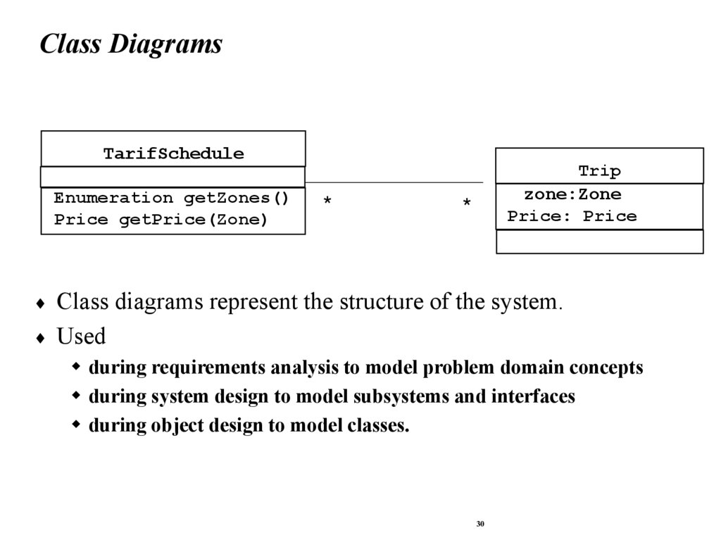
Class DiagramsTarifSchedule
Enumeration getZones()
Price getPrice(Zone)
*
Trip
zone:Zone
Price: Price
*
Class diagrams represent the structure of the system.
Used
during requirements analysis to model problem domain concepts
during system design to model subsystems and interfaces
during object design to model classes.
30
31.
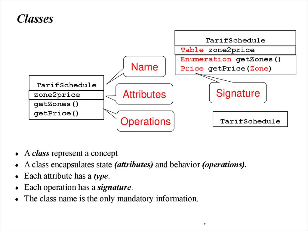
ClassesName
TarifSchedule
zone2price
getZones()
getPrice()
TarifSchedule
Table zone2price
Enumeration getZones()
Price getPrice(Zone)
Attributes
Signature
Operations
TarifSchedule
A class represent a concept
A class encapsulates state (attributes) and behavior (operations).
Each attribute has a type.
Each operation has a signature.
The class name is the only mandatory information.
31
32.
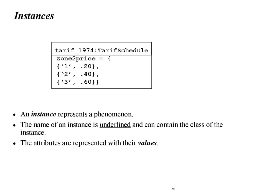
Instancestarif_1974:TarifSchedule
zone2price = {
{‘1’, .20},
{‘2’, .40},
{‘3’, .60}}
An instance represents a phenomenon.
The name of an instance is underlined and can contain the class of the
instance.
The attributes are represented with their values.
32
33.
Actor vs InstancesWhat is the difference between an actor , a class and an
instance?
Actor:
An entity outside the system to be modeled, interacting with the
system (“Passenger”)
Class:
An abstraction modeling an entity in the problem domain, must be
modeled inside the system (“User”)
Object:
A specific instance of a class (“Joe, the passenger who is purchasing
a ticket from the ticket distributor”).
33
34.
AssociationsTarifSchedule
TripLeg
Enumeration getZones()
Price getPrice(Zone)
Price
Zone
*
*
Associations denote relationships between classes.
The multiplicity of an association end denotes how many objects the source
object can legitimately reference.
34
35.
1-to-1 and 1-to-many AssociationsHas-capital
Country
City
*
name:String
name:String
One-to-one association
Point
Polygon
*
x: Integer
y: Integer
draw()
One-to-many association
35
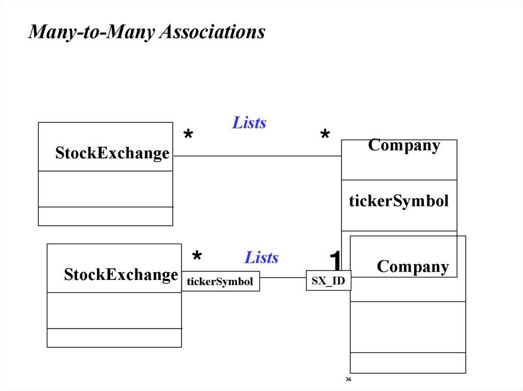
36.
Many-to-Many AssociationsStockExchange
*
Lists
*
Company
tickerSymbol
StockExchange *
Lists
tickerSymbol
1
Company
SX_ID
36
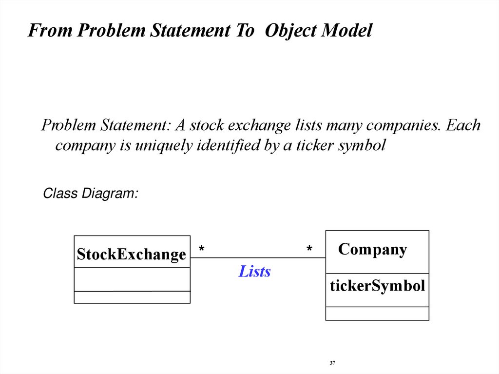
37.
From Problem Statement To Object ModelProblem Statement: A stock exchange lists many companies. Each
company is uniquely identified by a ticker symbol
Class Diagram:
StockExchange *
Company
*
Lists
tickerSymbol
37
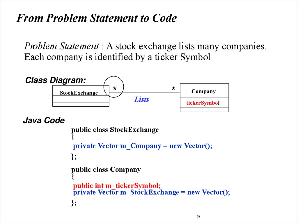
38.
From Problem Statement to CodeProblem Statement : A stock exchange lists many companies.
Each company is identified by a ticker Symbol
Class Diagram:
StockExchange
*
Lists
*
Company
tickerSymbol
Java Code
public class StockExchange
{
private Vector m_Company = new Vector();
};
public class Company
{
public int m_tickerSymbol;
private Vector m_StockExchange = new Vector();
};
38
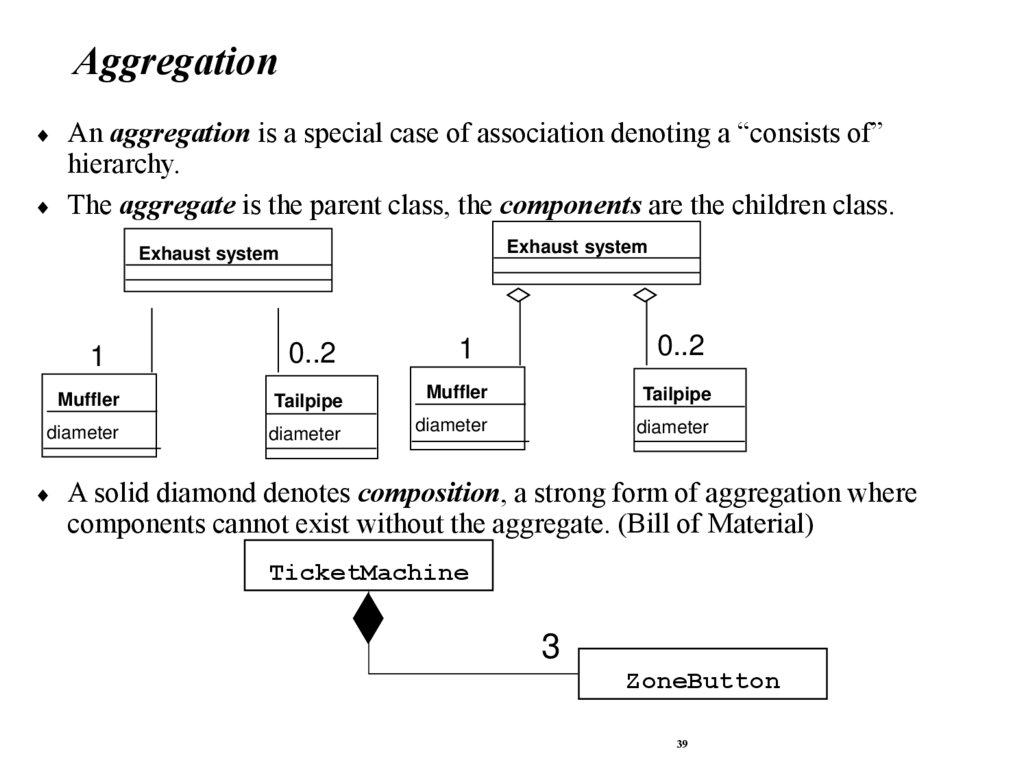
39.
AggregationAn aggregation is a special case of association denoting a “consists of”
hierarchy.
The aggregate is the parent class, the components are the children class.
Exhaust system
Exhaust system
1
0..2
1
0..2
Muffler
Tailpipe
Muffler
Tailpipe
diameter
diameter
diameter
diameter
A solid diamond denotes composition, a strong form of aggregation where
components cannot exist without the aggregate. (Bill of Material)
TicketMachine
3
ZoneButton
39
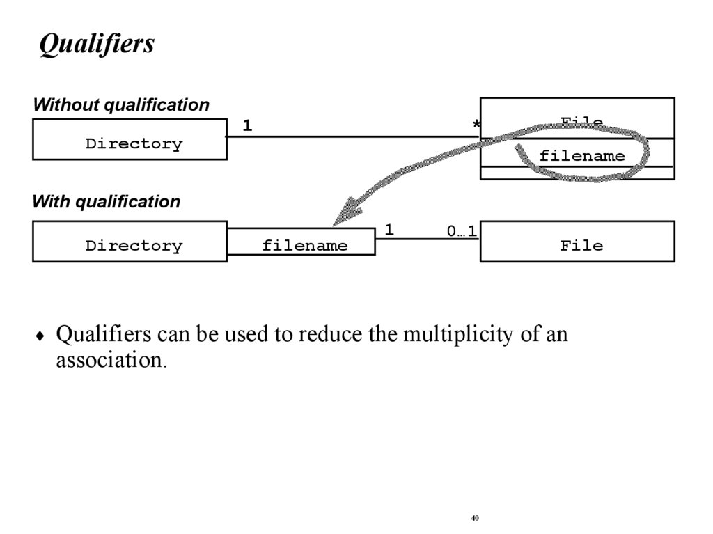
40.
QualifiersWithout qualification
Directory
1
*
File
filename
With qualification
Directory
filename
1
0…1
File
Qualifiers can be used to reduce the multiplicity of an
association.
40
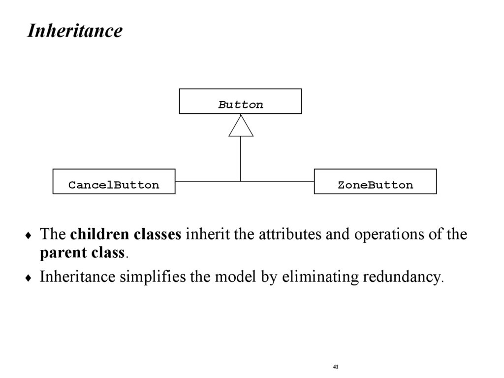
41.
InheritanceButton
CancelButton
ZoneButton
The children classes inherit the attributes and operations of the
parent class.
Inheritance simplifies the model by eliminating redundancy.
41
42.
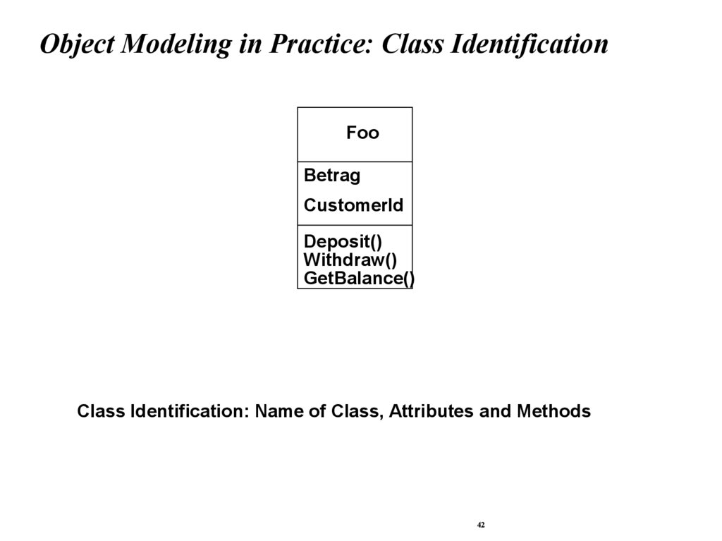
Object Modeling in Practice: Class IdentificationFoo
Betrag
CustomerId
Deposit()
Withdraw()
GetBalance()
Class Identification: Name of Class, Attributes and Methods
42
43.
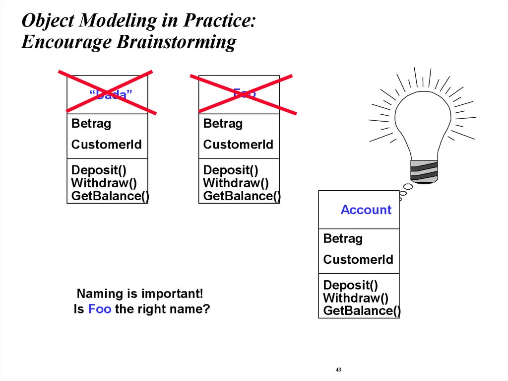
Object Modeling in Practice:Encourage Brainstorming
“Dada”
Foo
Betrag
Betrag
CustomerId
CustomerId
Deposit()
Withdraw()
GetBalance()
Deposit()
Withdraw()
GetBalance()
Account
Betrag
CustomerId
Naming is important!
Is Foo the right name?
Deposit()
Withdraw()
GetBalance()
43
44.
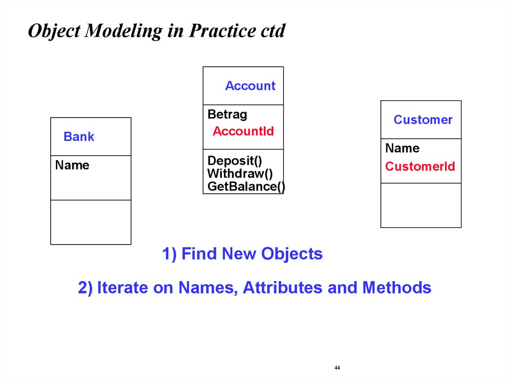
Object Modeling in Practice ctdAccount
Bank
Name
Betrag
AccountId
CustomerId
Customer
Name
CustomerId
Deposit()
Withdraw()
GetBalance()
1) Find New Objects
2) Iterate on Names, Attributes and Methods
44
45.
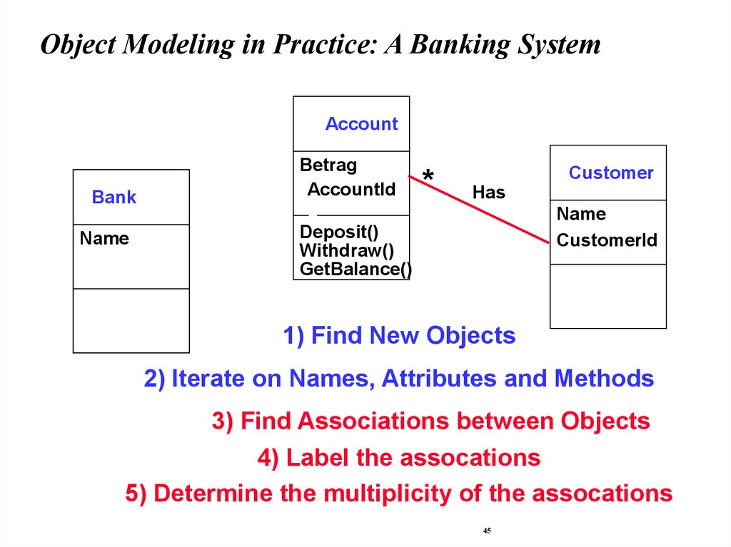
Object Modeling in Practice: A Banking SystemAccount
Bank
Name
Betrag
AccountId
CustomerId
AccountI
d
Deposit()
Withdraw()
GetBalance()
*
Customer
Has
Name
CustomerId
1) Find New Objects
2) Iterate on Names, Attributes and Methods
3) Find Associations between Objects
4) Label the assocations
5) Determine the multiplicity of the assocations
45
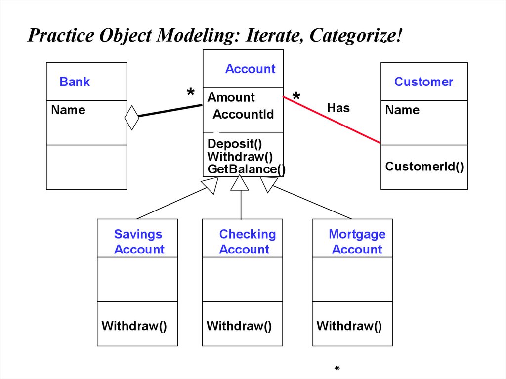
46.
Practice Object Modeling: Iterate, Categorize!Account
Bank
* Amount
Name
AccountId
CustomerId
AccountI
d
Deposit()
Withdraw()
GetBalance()
Customer
*
Has
Name
CustomerId()
Savings
Account
Checking
Account
Mortgage
Account
Withdraw()
Withdraw()
Withdraw()
46
47.
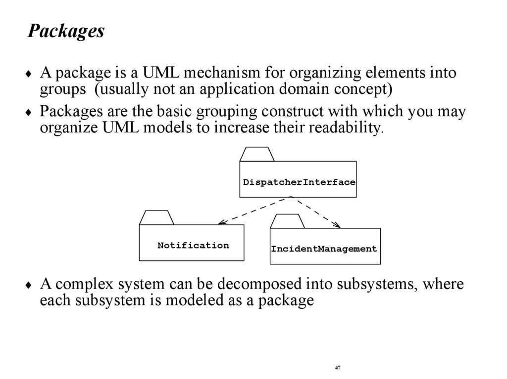
PackagesA package is a UML mechanism for organizing elements into
groups (usually not an application domain concept)
Packages are the basic grouping construct with which you may
organize UML models to increase their readability.
DispatcherInterface
Notification
IncidentManagement
A complex system can be decomposed into subsystems, where
each subsystem is modeled as a package
47
48.
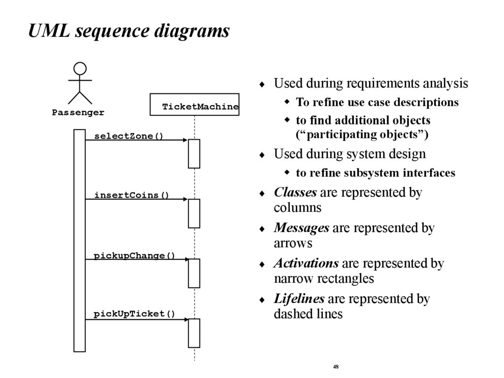
UML sequence diagramsPassenger
Used during requirements analysis
To refine use case descriptions
to find additional objects
(“participating objects”)
TicketMachine
selectZone()
Used during system design
to refine subsystem interfaces
insertCoins()
pickupChange()
pickUpTicket()
Classes are represented by
columns
Messages are represented by
arrows
Activations are represented by
narrow rectangles
Lifelines are represented by
dashed lines
48
49.
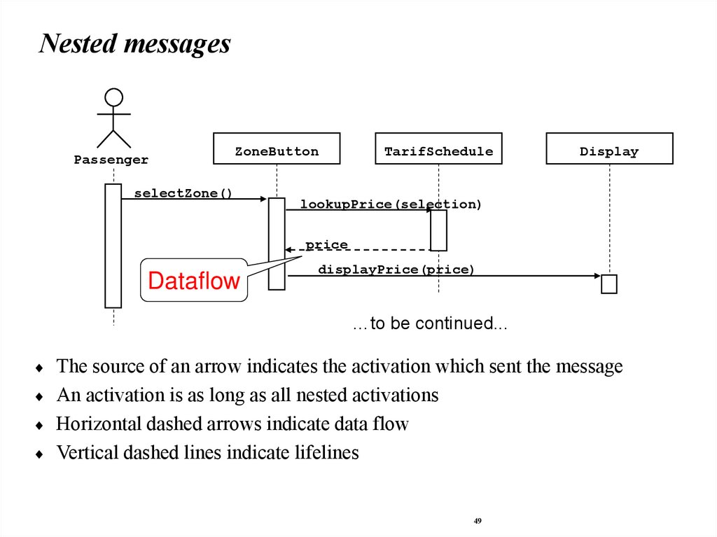
Nested messagesPassenger
ZoneButton
selectZone()
TarifSchedule
Display
lookupPrice(selection)
price
Dataflow
displayPrice(price)
…to be continued...
The source of an arrow indicates the activation which sent the message
An activation is as long as all nested activations
Horizontal dashed arrows indicate data flow
Vertical dashed lines indicate lifelines
49
50.
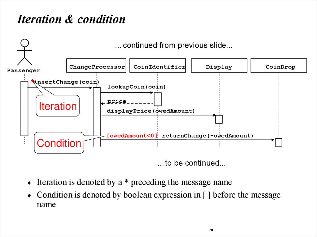
Iteration & condition…continued from previous slide...
Passenger
ChangeProcessor
CoinIdentifier
Display
CoinDrop
*insertChange(coin) lookupCoin(coin)
Iteration
price
displayPrice(owedAmount)
[owedAmount<0] returnChange(-owedAmount)
Condition
…to be continued...
Iteration is denoted by a * preceding the message name
Condition is denoted by boolean expression in [ ] before the message
name
50
51.
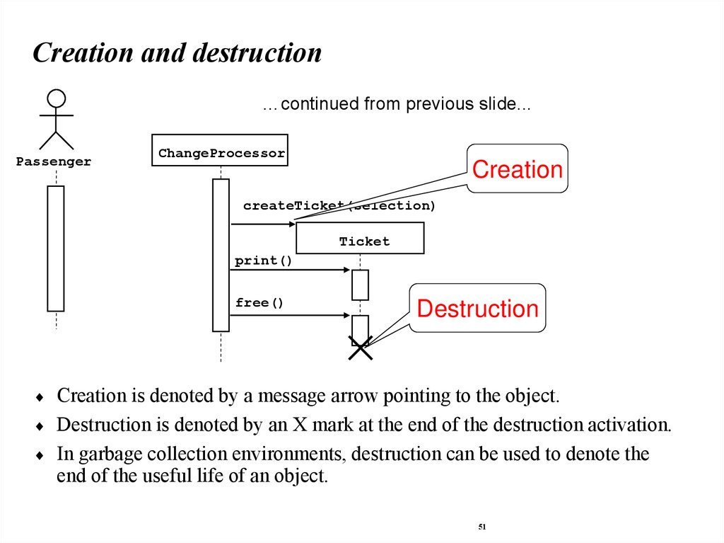
Creation and destruction…continued from previous slide...
Passenger
ChangeProcessor
Creation
createTicket(selection)
Ticket
print()
free()
Destruction
Creation is denoted by a message arrow pointing to the object.
Destruction is denoted by an X mark at the end of the destruction activation.
In garbage collection environments, destruction can be used to denote the
end of the useful life of an object.
51
52.
Sequence Diagram SummaryUML sequence diagram represent behavior in terms of
interactions.
Useful to find missing objects.
Time consuming to build but worth the investment.
Complement the class diagrams (which represent structure).
52
53.
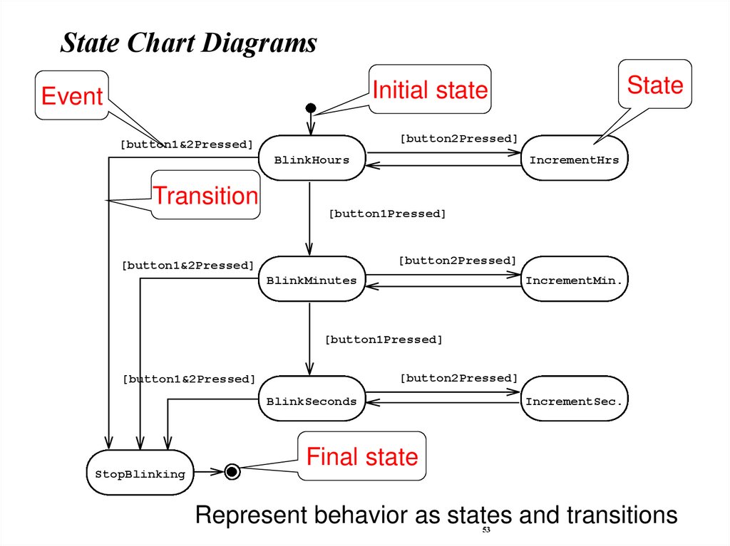
State Chart DiagramsState
Initial state
Event
[button2Pressed]
[button1&2Pressed]
BlinkHours
Transition
IncrementHrs
[button1Pressed]
[button2Pressed]
[button1&2Pressed]
BlinkMinutes
IncrementMin.
[button1Pressed]
[button2Pressed]
[button1&2Pressed]
BlinkSeconds
StopBlinking
IncrementSec.
Final state
Represent behavior as states and transitions
53
54.
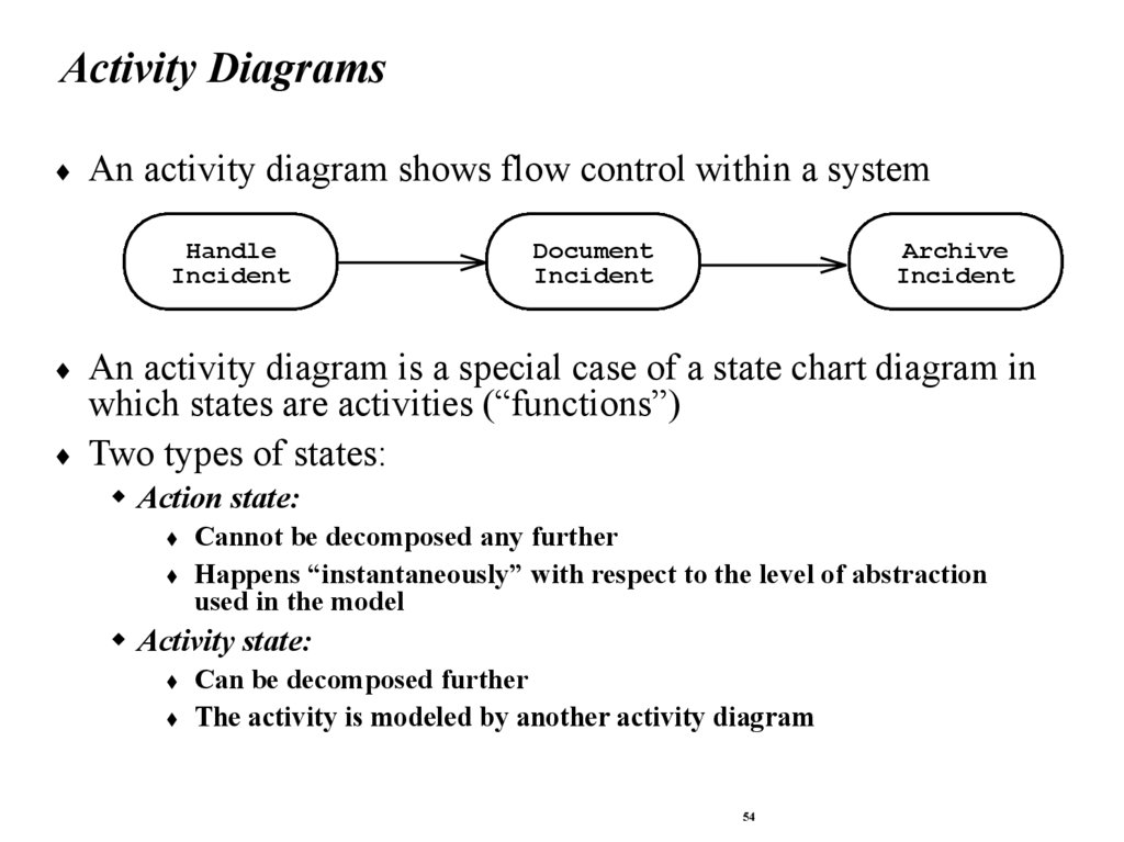
Activity DiagramsAn activity diagram shows flow control within a system
Handle
Incident
Document
Incident
Archive
Incident
An activity diagram is a special case of a state chart diagram in
which states are activities (“functions”)
Two types of states:
Action state:
Cannot be decomposed any further
Happens “instantaneously” with respect to the level of abstraction
used in the model
Activity state:
Can be decomposed further
The activity is modeled by another activity diagram
54
55.
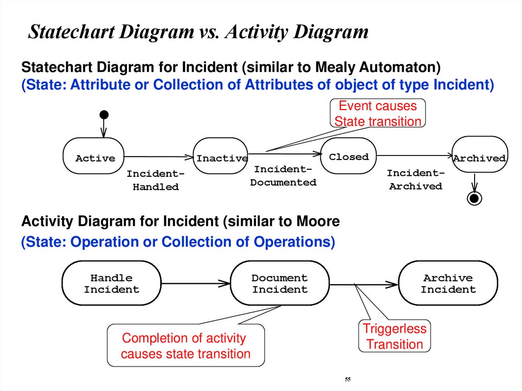
Statechart Diagram vs. Activity DiagramStatechart Diagram for Incident (similar to Mealy Automaton)
(State: Attribute or Collection of Attributes of object of type Incident)
Event causes
State transition
Active
Inactive
IncidentHandled
Closed
IncidentDocumented
Archived
IncidentArchived
Activity Diagram for Incident (similar to Moore
(State: Operation or Collection of Operations)
Handle
Incident
Document
Incident
Archive
Incident
Triggerless
Transition
Completion of activity
causes state transition
55
56.
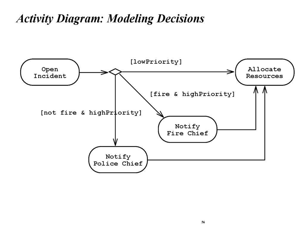
Activity Diagram: Modeling Decisions[lowPriority]
Open
Incident
Allocate
Resources
[fire & highPriority]
[not fire & highPriority]
Notify
Fire Chief
Notify
Police Chief
56
57.
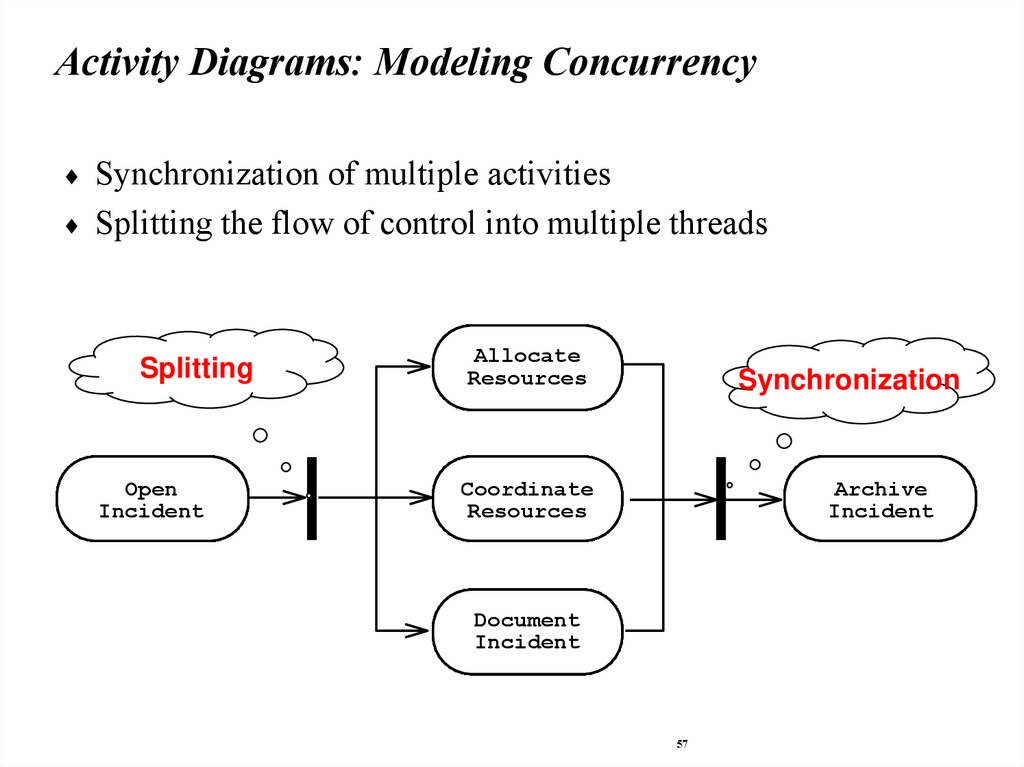
Activity Diagrams: Modeling ConcurrencySynchronization of multiple activities
Splitting the flow of control into multiple threads
Splitting
Open
Incident
Allocate
Resources
Synchronization
Coordinate
Resources
Archive
Incident
Document
Incident
57
58.
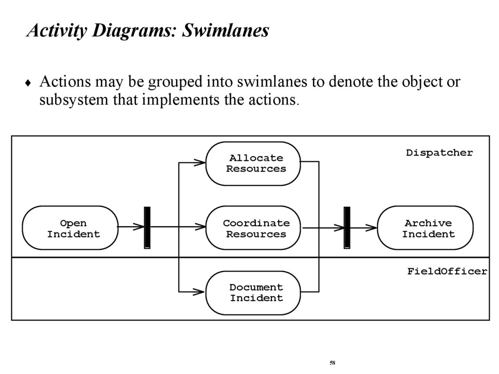
Activity Diagrams: SwimlanesActions may be grouped into swimlanes to denote the object or
subsystem that implements the actions.
Open
Incident
Allocate
Resources
Dispatcher
Coordinate
Resources
Archive
Incident
FieldOfficer
Document
Incident
58
59.
What should be done first? Coding or Modeling?It all depends….
Forward Engineering:
Creation of code from a model
Greenfield projects
Reverse Engineering:
Creation of a model from code
Interface or reengineering projects
Roundtrip Engineering:
Move constantly between forward and reverse engineering
Useful when requirements, technology and schedule are changing
frequently
59
60.
UML SummaryUML provides a wide variety of notations for representing
many aspects of software development
Powerful, but complex language
Can be misused to generate unreadable models
Can be misunderstood when using too many exotic features
For now we concentrate on a few notations:
Functional model: Use case diagram
Object model: class diagram
Dynamic model: sequence diagrams, statechart and activity
diagrams
60
61.
Models for Plato’s and Aristotle’s Views of RealityPlato
Material reality is a second-class
subordinate type of reality.
The first-class type is a “form”
Forms lie behind every thing or in
the world. Forms can be abstract
nouns like “beauty” or “mammal”
or concrete nouns like “tree” or
“horse”.
There is an important difference
between the world of forms and
particulars. Forms are nonmaterial,
particulars are material. Forms are
permanent and changeless.
Particulars are changing.
Forms can be acquired
intellectually through a “dialectic”
process that moves toward the
highest understanding of reality
through the interaction of questions
and answers.
Aristotle
Aristotle accepted the reality of Forms as
nonmaterial entities.
However, he could not accept Plato’s idea,
that these Forms were not real.
Instead of two separate worlds, one for
Forms and one for Particulars, Aristotle
had only one world, a world of particular
things.
Particular things according to Aristotle
have a certain permance about them, even
while they are subject to change: A tree
changes colors without ceasing to be a
tree. A horse grows in size without ceasing
to be a horse.
What is the root of this permancence? It is
the thing’s internal form, which minds
detect, when they penetrate beyond the
thing’s changing attributes. So for
Aristotle, reality is thus made up of
particular things that are each composed of
form antdn matter..
61
62.
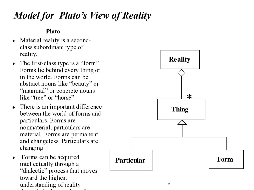
Model for Plato’s View of RealityPlato
Material reality is a secondclass subordinate type of
reality.
The first-class type is a “form”
Forms lie behind every thing or
in the world. Forms can be
abstract nouns like “beauty” or
“mammal” or concrete nouns
like “tree” or “horse”.
There is an important difference
between the world of forms and
particulars. Forms are
nonmaterial, particulars are
material. Forms are permanent
and changeless. Particulars are
changing.
Forms can be acquired
intellectually through a
“dialectic” process that moves
toward the highest
understanding of reality
Reality
*
Thing
Form
Particular
62
63.
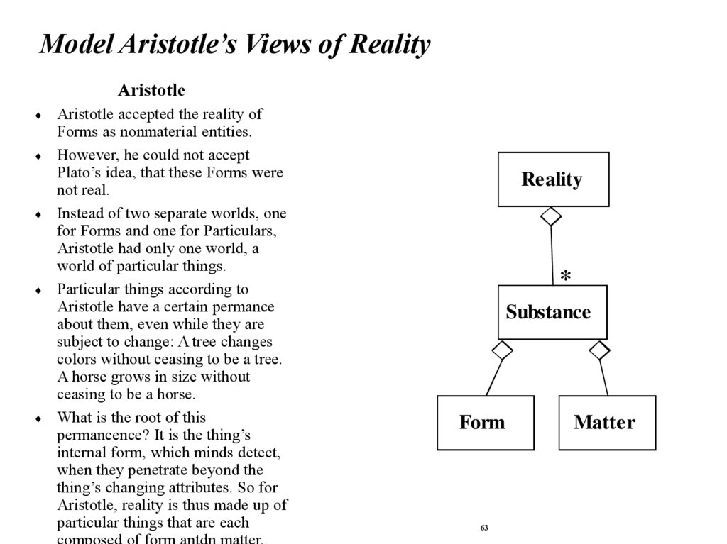
Model Aristotle’s Views of RealityAristotle
Aristotle accepted the reality of
Forms as nonmaterial entities.
However, he could not accept
Plato’s idea, that these Forms were
not real.
Instead of two separate worlds, one
for Forms and one for Particulars,
Aristotle had only one world, a
world of particular things.
Particular things according to
Aristotle have a certain permance
about them, even while they are
subject to change: A tree changes
colors without ceasing to be a tree.
A horse grows in size without
ceasing to be a horse.
What is the root of this
permancence? It is the thing’s
internal form, which minds detect,
when they penetrate beyond the
thing’s changing attributes. So for
Aristotle, reality is thus made up of
particular things that are each
composed of form antdn matter..
Reality
*
Substance
Form
63
Matter
64.
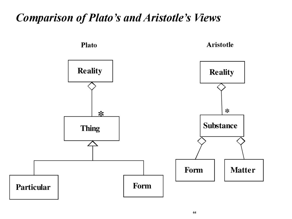
Comparison of Plato’s and Aristotle’s ViewsPlato
Aristotle
Reality
Reality
*
*
Substance
Thing
Form
Particular
Form
64
Matter