


 industry
Similar presentations:


QJ340. Build Procedure
1. QJ340 Build Procedure
Sandvik Mining and Construction2.
This document is for reference ONLY Sandvik take no responsibility forinjury or damaged cause during the assembly of the Jaw crusher, from
information supplied in this document
Sandvik Mining and Construction
3. Inner Bearing through the Jawstock
First clean and de-burr the jaw Stock Part #J4000000
Grind a leading edge on the inside of the bore
as shown and clear ensuring free of any
oil/debris
Now measure the bores with a internal
micrometer
They should measure 420.00- 420.06mm
(please see drawing on next page)
Once clean, bearing Part # BT3065 should be
tested to see if it passes through the jaw stock
Clean all bolt holes either side of the jawstock
eliminating any oil or debris
This will ensure ease of assembly later on
Sandvik Mining and Construction
M20x2.5 tap used to
clean
4. Jawstock Part # J4000000 Drawing
420.00 –420.06mm
If these measurement are
out of spec then please
report to Sandvik before
proceeding
Sandvik Mining and Construction
Ensure that the grease
nipple holes and the lifting
holes are clean from
debris.
5. Shaft Assembly
Clean shaft Part # J4110000 removingany dirt/grease
De-burr any sharp edges from the
shaft using a suitable file and emery
cloth
Now measure that shaft to ensure it
is with in specification, please see
attached drawing
Sandvik Mining and Construction
6. Shaft Assembly
Sandvik Mining and Construction209.75 209.85mm
239.89 –
240.00mm
If these measurement are out of spec then
please report to Sandvik Engineering and
Quality department before proceeding
280.06 –
280.09mm
Shaft Assembly
7. Shaft Assembly
Serial NumberOn the End of the shaft
is a Stamped the shafts
part number and a Shaft
Serial number,
Record the Serial
number of the shaft for
traceability
Part Number
Sandvik Mining and Construction
8. Shaft Assembly spacers
Clean the inner shaft spacers Part #J4120000 and ensure the location
faces have been de-burred
Ensure the inner bore measures
between 280.13mm to 280.19mm
Slide the spacers onto the shaft as
shown, ensuring that they are tight up
against the shoulder on the shaft
Do this for both side of the shaft
Sandvik Mining and Construction
9. Shaft Assembly Inner Bearings
Check clearance herewith feeler blades
Before fitting bearings Part # BT3065
check the inner diameter with an
internal micrometer
This should be 279.97 – 280.00
The clearance of the bearing should
also be checked. This should measure
between 0.26 – 0.35mm (when the
bearing is lifted as shown this should
be checked at the top of the race over
a full roller)
Now place the bearing onto an
induction heater and heat the bearing
up to 110°C
Sandvik Mining and Construction
When lifting the bearing a
suitable lifting cradle or
strap should be used
10. Shaft Assembly Inner Bearings
Once the bearing is up totemperature lift using a strap or
suitable lifting equipment and slide
onto the shaft
Once fitted ensure it is hard up to
the inner spacer and keep a bar on
the inner race as shown until the
bearing has cooled and gripped the
shaft.
Carry out this procedure for both
sides
Once cool the bearing clearance
should now be checked again with
feeler blades at the top over 1 roller
on each side. The measurement
should be 0.16 – 0.29mm
Once cool pack the bearing with SKF
LGHB2 grade grease
Sandvik Mining and Construction
Caution the bearing is extremely hot use the
appropriate PPE when handling
11. Jawstock Assembly
Drive side of thejaw stock
Place the jaw stock as shown
in line with a fixed object
suitable for pulling against as
shown
Ensure that the drive side of
the jaw stock is towards the
fixed object
Place a brace 1500mm long
between the fixed object and
the jaw stock
Sandvik Mining and Construction
1500mm long
brace
12. Jawstock Assembly
For pulling the shaft assemblythrough the bore you will need
to bolt the pulling plate to the
end of the shaft as shown
(drawing on following page)
you will also require a 1 – 1 ½
ton pull lift and suitable strap to
attach to the fixed object as
shown. This will be used to pull
the shaft into the jaw stock
Sandvik Mining and Construction
13. Shaft Pulling Plate
Sandvik Mining and Construction14. Jawstock Assembly
To fit the shaft assembly firstlightly oil the bores of the jaw
stock
Now lift the shaft assembly in
the centre as shown.
Start the bearing/shaft assembly
In one end of the jaw stock
Sandvik Mining and Construction
15. Jaw Stock Assembly
Once the bearing has started attach thepull lifts to the shaft
And slowly pull the shaft assembly into
the jaw stock
Ensure that the bearing is square at all
times
When required you can tap the bearing
square using a soft steel bar
When the first bearing has entered into
the jaw stock you will have to lower the
shaft assembly on to a suitable support as
shown
Then relocate the crane chains to the end
of the shaft
Sandvik Mining and Construction
16. Jaw Stock Assembly
Now you have re-lifted the shaftassembly, proceed to pull the shaft
assembly through the jaw stock
Pull the shaft assembly through until
both bearings are about to start in their
relevant bores.
Now you may have to re-lift the shaft
from either side to lift the bearings
over the step in the bore
Ensure that the shaft is square to the
jaw stock bore at all times
Sandvik Mining and Construction
17. Jawstock Drive Side Assembly
Bearing protrusion20mm
Pull the shaft assembly through until the
bearing protrudes from the jaw stock by
over approximately 20mm
Now remove the pull lift from the end of
the shaft.
Before fitting the Jawstock Housing
Cover Part # J4130000 carry out the
following checks
The depth should be 13.13mm –
13.07mm (if not please contact the
Sandvik Engineering / Quality
department)
Sandvik Mining and Construction
Check clearance at
the top of the bearing
Measure from the
location face down
to the first step
18. Jawstock Drive Side Assembly
Place the jawstock housing cover Part #J4130000 on to the dive side of the jaw stock
Fit four M20x45 cap screws at equal points
around the plate then slowly pull the plate tight
against the bearing
With the plate touching the bearing keep
tightening the 4 bolts and this will force the shaft
assembly back through the jawstock. Ensuring the
cover plate is tight against the jawstock.
Now re-attach the pull lifts and pull the whole
assembly tight up against the spacer plate
Tap the non-drive side bearing with a soft bar to
ensure the bearing is tight up
Sandvik Mining and Construction
This done to ensure the whole
shaft assembly is tight against the
drive side
19. Jawstock end float
Remove the pull lifts and with the shaftassembly tight up against the spacer
measure the bearing protrusion on the
none drive side as shown,
Make a note of the measurement
(approximately 13mm)
Now measure the depth of the none drive
Jaw stock cover plate Part # J4130000 as
shown and make a note (normally 13mm)
1mm – 1.25mm of end float clearance is
required between the outer bearing and the
spacer so this will require machining please
see next page for details
Sandvik Mining and Construction
20. Jawstock end float
As there needs to be 1 – 1.25mm of float between the spacer and the bearing faceyou will either have to machine the bottom step if there is not enough float or
machine the location face if there is too much float
Location face
Bottom step
Sandvik Mining and Construction
21. Jawstock Non-Drive Side Assembly
Once the spacer hasbeen machined offer it
onto the none drive side
Bolt the cover plate onto
the jaw stock using
M20x45 cap screws and
apply “Lock Tight 2701”
then torque to 685N/M
Carry out this procedure
for both of the jaw stock
cover plates
Sandvik Mining and Construction
22. Greasing
The bearings need to be fullypurged with grease.
To do this attach the grease line
to the grease point on the jaw
stock and then pump grease into
the jaw stock until it protrudes
out of the shaft assembly as
shown using SKF LGHB2
Carry out this grease procedure
for both side of the jaw stock
Sandvik Mining and Construction
23. Labyrinth Spacers
The labyrinth spacers Part # J4140000should be cleaned and de-burred
Measure the inner bore of the spacers.
They should measure between
240.11mm to 240.17mm
Once clean they can be placed onto
the shaft as shown tight up against the
shoulder of the shaft
Place these spacers on both sides of
the shaft
Then pump grease all of the way
around the labyrinth groove
Sandvik Mining and Construction
24. Bearing Housings
The drive side has a steplocated in the bottom of
the housing
The bearing housing for the outer
bearing must be cleaned and deburred.
Ensure that all of the tapped holes are
clean of any oil/grease or foreign
objects
Drive Side Bearing
Housing J4150000
Then measure the bore diameter of
both housing. These should measure
between 440.00mm – 440.06mm
If these housing are out side of
tolerance, report to the Sandvik
Engineering / quality department
before proceeding
Sandvik Mining and Construction
Non-Drive Side Bearing
Housing J4170000
25. Bearing housing Assembly
Smear a light film of grease on the bores ofthe cartridges
Before fitting the bearing Part # BT3060
ensure the bearing numbers are to the
outside face and the taper is as shown
(Note the centre of the bearing can be
rotated if required)
Lower the bearing down into the housing as
shown
Tap the bearing into the housing squarely
using a soft metal bar ensuring the bearing
is fully down into the housing
Sandvik Mining and Construction
26. Bearing housing Assembly
A measurement should be taken and recorded from the outer face of thebearing housing to the bearing outer race.
Drive Side normal 13mm
Non-drive side normally 15-18mm
Sandvik Mining and Construction
27. Bearing Housing fitting
Check the bearing clearancebefore fitting this should be 0.3 –
0.39mm
This should be measured at the
top when lifted over a full roller
Note this down for both
bearings
Lift the cartridge assembly using
a suitable lifting strap
Clean the bearing taper and then
fit offer the cartridge assembly in
place over the shaft
Sandvik Mining and Construction
28. Bearing sleeve
Locking ScrewPart # J4190000
Before fitting the bearing sleeve’s
Part # BT3501 onto the shaft first
clean with a clean cloth
Screw on the bearing locking ring
Part # J4190000 to ensures the
sleeve is kept square when mounting
Now slowly slide the sleeve onto the
shaft and into the bearing push until
firm.
Sandvik Mining and Construction
Sleeve Part #
BT 3501
29. Bearing Housing Assembly
Before proceeding ensure the bearing housing are on thecorrect side as show below
Non-Drive side
bearing housing
Part # J4170000
Drive side bearing
housing Part #
J4150000
Sandvik Mining and Construction
30. Bearing Housing Clearance
To take the clearance out of thebearing you must first remove the
locking screw from the bearing
sleeve
And then attached a hydraulic
assembly nut Part # BT7511
(HMV 56E) to the bearing sleeve
ensuring the piston of the nut is
facing out away from the jaw
stock
Now place the spaces as shown
(please see following page for
spacers details)
Sandvik Mining and Construction
31. Spacer Dimensions
Sandvik Mining and Construction32. Spacer Dimensions
Sandvik Mining and Construction33. Bearing Housing Clearance
Attach a suitable hydraulic Portapower to the hydraulic nut and
then open the pump to allow the
oil to return back into it
Tighten the end plate to retract the
hydraulic piston fully into the nut
(this will give you the full stroke of
the nut)
Now lock the Porta power and
start pumping the hydraulic nut,
pressurise up until tight.
Sandvik Mining and Construction
34. Bearing Clearance
Now open the Porta power to allow thepressure out of the hydraulic nut
Make a note of all measurement
taken
Now check the clearance again.You should
reduce the clearance by 0.12 – 0.17mm from
the before fitting measurement taken earlier
If this is not achieved you will have to carry
out the procedure on the previous page and
pressurise up the hydraulic nut again
The clearance has to be greater than 0.14mm
after fitting
(note if the clearance after fitting is below
0.14mm then you will have to remove the
sleeve and start again)
Carry out the same procedure for both sides
Sandvik Mining and Construction
Check clearance as show at the bottom of
the bearing fully over 1 roller as the weight
of the bearing is at the top
35. Bearing sleeve checks
Once both bearings have been fittedand are at the correct clearance
Check the distance from the end of
the shaft to the bearings inner race
this should be 211mm ± 0.75mm
If this measurement is out of
specification contact Sandvik design /
quality department before proceeding
Sandvik Mining and Construction
36. Bearing Locking Ring
Now screw onto thebearing sleeve the bearing
locking ring Part #
J4190000
Then tighten the locking
ring with a “C” spanner as
shown
Carry this out for both
sides of the shaft
Sandvik Mining and Construction
37. Housing Cover Assembly
Drive side cover has twosteps as shown
Drive Side Housing Cover
Part # J4160000
Measure and record the depth from
the step to the mating face as
shown
Sandvik Mining and Construction
Non-Drive Side Housing
Cover Part # J4180000
38. Drive Side Housing Cover Assembly
Now that we have measurethe depth of the space and
the depth of the bearing
earlier
The amount of
float/difference between
these should be 0 – 0.13mm
(drive side)
Depth of Bearing – Depth of
Step = Float
Sandvik Mining and Construction
Drive Side Housing Cover
Part # J4160000
39. Non-Drive Side Housing Cover Assembly
Now that we have measure thedepth of the space and the
depth of the bearing earlier
The amount of float/difference
between these should be 7 –
9mm (Non drive side)
Depth of Bearing – Depth of
Step = Float
Please make note of the float
as you will need to know this
later in the build
Sandvik Mining and Construction
Non-Drive Side Housing
Cover Part # J4180000
40. Housing Cover Assembly
You can now bolt the drive side housingcovers to the bearing housings
Using Loctite “2701” and then torque to
566N/M (10.9 grade bolts)
On the Non-Drive side just place 4 bolts
holding the cover plate on as you will
have to remove this cover later in the
build
Drive side
Ensure that a 0.05mm feeler gauge will
not fit between the cover plate and
bearing housing
Ensure that the clearance between the
bearing outer race and outer cover is
less than 0.13mm (check with feeler
gauge)
Sandvik Mining and Construction
41. Ensure “Y” Brackets Fit
Before fitting the toggle seatensure that the Toggle Jaw
Brackets Part # J8080000 &
J8090000 fit and do not foul
on the jaw stock casting
Grind the jaw stock casting
if necessary to allow the
Toggle Jaw brackets to fit
Sandvik Mining and Construction
42. Rubber Skirt Fitting
It will be necessary to drill and tapthe jaw stock as per the attached
drawing
Drill the holes using a 7.5mm drill
bit and the tap using a M10x1.5 tap
You can now fit the Jaw Crusher
Toggle Protection Rubber Part #
RU1139 and Toggle Dust Clamp
Part # J0370000
Use M10x35 along with M10 flat &
spring washers
After fitting of rubber tie up to aid
fitting later
Sandvik Mining and Construction
43. Toggle Seat
Ensure the jaw stock where thetoggle seat will fit is clean and free
of any foreign objects
Fit the Toggle seat Part #
J5270000 as shown tap with a soft
hammer until central in the jaw
stock
To prevent the Toggle seat falling
out during lifting secure by fitting
a bolt in either side of the jaw
stock and using either heavy duty
tie wraps as shown or steel wire
and twist tighten / secure
Sandvik Mining and Construction
44. Swing Jaw Plate
Set the jaw stock on a suitableplatform as shown to fit the
swing jaw plate
Now using lifting equipment
Part # J6360000, J4840000 &
FADL1006 raise Swing jaw
plate as shown
Jaw plates types are listed in
the table
Part #
J4260000
J4710000
J2960000
J5790000
Description
Tall Tooth
Corrugated 13%
Corrugated 18%
Square
Sandvik Mining and Construction
45. Swing Jaw Plate
When fitting the swing jaw plate it is imperative that the recesses in theSwing jaw plate locate on the Key of the Jaw stock as failure to do so
will cause the plate to fall off
Sandvik Mining and Construction
46. Swing Jaw Plate Retaining Wedges
Wedges in place on thejaw stock
Now the jaw plate is sitting on
the jaw stock fit the
appropriate wedges on to the
jaw stock. See table below for
correct wedge
Place the wedges in position
and fit the wedge bolts Part #
J4300000 through the wedge
and jaw stock
Part #
J4280000
J4750000
J4950000
J4940000
Description
Sandvik Mining and Construction
Tall Tooth
Corrugated
Fit bolts
J4300000
47. Top Impact Wear Plate
With the wedges in place lift the impactwear plate J5030000 into place
Then using the bolts and washers listed,
apply Loctite 2701 and tighten up to
secure wear plate into place. Torque bolts
to 566 N/m
M20x90, M20 Flat Washers &
M20 Spring Washers
M20x50 & M20 Nor loc
Washers
Sandvik Mining and Construction
48. Tightening the Swing Jaw Plate
Orientation of the DisksTake the weight of the jaw stock
using suitable lifting equipment
Now fit the top hat, washers and
nut as shown
Tighten fully until the spring
washers have been compressed
Top Hat Washer
Part # J5990000
M42 Loc Nut
Compression Disk
Part # SC1006 x 4
Sandvik Mining and Construction
Disk Washer Part
# J3990000
49. Crusher Mainframe Assembly
Lift the L/H side wall Part #J4030000 with a suitable “D”
shackle and crane as shown
Place 7 M48x200 Bolts from
the out side face inwards in
the bolt holes shown and
then screw onto the bolts
M48 Nuts, as this will stop
the bolts falling out when
lowering
Out side face of the
side plate is machined
around the bearing
housing location point
Bolt location
Now lower the plate down
onto the outer face of the
side plate and unscrew the
M48 nuts
Please record L/H and R/H
plate serial numbers
Sandvik Mining and Construction
50. Crusher Mainframe Assembly
R/H side plateJ4020000
With the L/H side plate on the floor lower
into place the Frontbeam Part # J4010000
and the Backbeam Part # J4020000
With the front and back beam in place the
R/H side plate Part # J4040000 can be
lowered in place on top of them as shown
Then place 7 M48x200 bolts it the location
shown
Frontbeam
J4010000
Bolt spacer J4060000
Then apply anti seize compound to the
threads
With all the bolts in place fit the Bolt Spacer
Washers Part # J4060000 along with M48
nuts and then tighten by hand
Please record Front beam and
Backbeam
serial
numbers
Sandvik
Mining and
Construction
Backbeam
J4020000
Bolt location
M48 Nut
51. Mainframe Mounting Feet
With the bolts and nuts fitted tight lift the jaw mainframe assembly to a standingposition as shown
The front and rear mounting feet can now be added L/ Front Part # J8000000, L/H
Rear Part # J8010000, R/H Front Part # J8020000 & R/H Rear Part # J8030000
The mounting feet are held on with M48x240 bolts along with Bolt Spacers Part #
J4060000
Bolt spacer J4060000
M48 Nut
Sandvik Mining and Construction
52. Mainframe Flywheel Cover Base
The Drive side cover base Part # J4760000 and Non-Drive side coverbase Part # J4800000 can now be offered into place and fitted
Using M24x60 (10.9) bolt along with M24 hardened washers torque to
979N/m
Non-Drive Side Cover Base
J4800000
Sandvik Mining and Construction
Drive Side Cover Base
J4760000
53. Ram Spigot Assembly
To fit the Ram Spigot Part # J4520000 first clean and de-greaseThen apply stud lock to the face shown and insert into the mainframe on the
L/H and R/H side with the pin facing into the mainframe
Tighten onto the mainframe using M48 nut and torque to 3200N/M
Spigot J4520000
Sandvik Mining and Construction
Spigot location
Fitted into position
54. Mainframe Bolt Torque
Torque the 24 mainframe bolts up to 6045N/M Wet (anti seizecompound fitted) (8060N/M Dry)
12 on the L/H side and 12 on the R/H side
Sandvik Mining and Construction
55. Cheek Plates
The cheek plates can be fitted on theinside of the mainframe
Start by fitting the bottom cheek plates
firsts L/H BTM Part # J4600000 & R/H
BTM Part # J4610000 hold into place
with M24x100 bolts M24 flat washers and
M24 locking nuts
(please note the lower cheek plate
bottom fixing uses a M24 x 80 bolt from
the out side of the box into the plate)
The Top Cheek plates can now be fitted
L/H TOP Part # J4580000 & R/H Top Part
# J4590000 use the same size bolts and
washers as the bottom plate
Sandvik Mining and Construction
M24 x 80
56. Toggle Ram Base Bracket
Base BracketJ4450000
Offer up the Toggle Wedge
Ram Base Bracket Part #
J4450000 and then secure in
place with M24x65 (10.9)
bolts along with M24 locking
washers
Place these in loosely until
other components are fitted
Bolt and washer
fixings
Sandvik Mining and Construction
57. Pull Arm Back Beam Pin
Ensure the Pin is clean and freefrom grease
Then apply anti seize grease to
the shaft in the location shown
Insert into the back beam and
then lock in place with a M64
Nut
Torque this up to 3200N/M
Sandvik Mining and Construction
58. Fixed jaw sleeves & Removal Ram
Fixed jaw sleeves & Removal RamRam
HR1052
Mount the hydraulic
removal ram Part #
HR1052 to the front wall
with 3 M16x40bolts along
with M16 flat washers
Also the two Wear Plate
Clamping Sleeves Part #
J5080000 can be mounted
with 3 M16x40 bolts along
with M16 flat washers
Torque these to 206 N/M
Sleeve
J5080000
Sandvik Mining and Construction
59. Fixed Jaw Plate Fitment
Lifting devicelocated correctly
Before lifting the fixed jaw
plate ensure the back face and
pockets are cleaner of debris
Lift the fixed jaw plate using
lifting equipment Part #
J6360000, J4840000 &
FADL1006
Ensure that the lifting device is
locating in the correct manner
as shown and not protruding
too far through the fixed jaw
plate
As this will hinder fitment
Sandvik Mining and Construction
60.
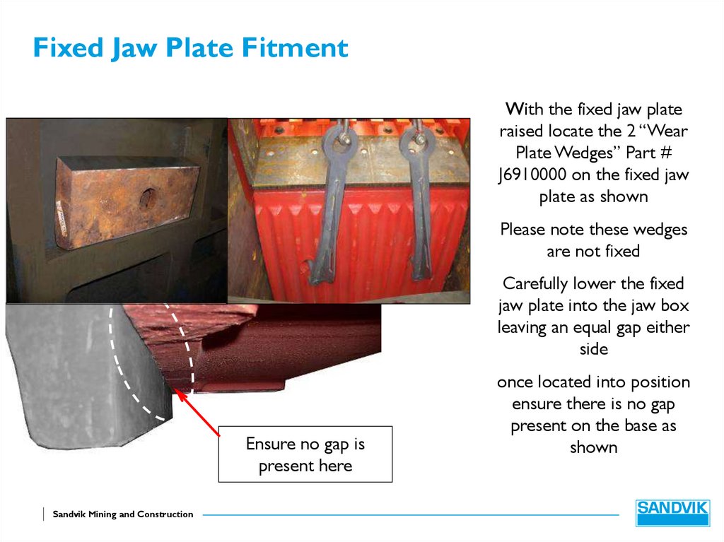
Fixed Jaw Plate FitmentWith the fixed jaw plate
raised locate the 2 “Wear
Plate Wedges” Part #
J6910000 on the fixed jaw
plate as shown
Please note these wedges
are not fixed
Carefully lower the fixed
jaw plate into the jaw box
leaving an equal gap either
side
Ensure no gap is
present here
Sandvik Mining and Construction
once located into position
ensure there is no gap
present on the base as
shown
61. Fixed Jaw Plate Fitment
Remove the lifting device from the fixedjaw plate
Danger, please note the fixed jaw plate is
now loose
Fit the two “Wedge Bolts” Part #
J4290000.
Hold in place with two plain M42 nuts
and then centralise the fixed jaw plate
using a suitable pry bar.
Now central tighten the M42 bolts to
3825 N/M
Fit two M42 Nyloc nuts Part # FAN42N
and tighten to 3825 N/M
Sandvik Mining and Construction
62. Wedge Assembly
To fit the wedgeassembly the
mainframe must be
lifted so that the
wedge location area is
parallel to the ground
this will aid ease of
assembly
Once in position
support on a suitable
platform
Sandvik Mining and Construction
Wedge assembly
area parallel to the
ground
63.
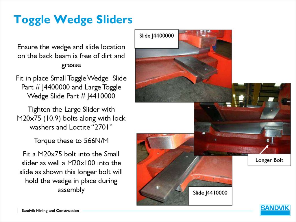
Toggle Wedge SlidersSlide J4400000
Ensure the wedge and slide location
on the back beam is free of dirt and
grease
Fit in place Small Toggle Wedge Slide
Part # J4400000 and Large Toggle
Wedge Slide Part # J4410000
Tighten the Large Slider with
M20x75 (10.9) bolts along with lock
washers and Loctite “2701”
Torque these to 566N/M
Fit a M20x75 bolt into the Small
slider as well a M20x100 into the
slide as shown this longer bolt will
hold the wedge in place during
assembly
Sandvik Mining and Construction
Longer Bolt
Slide J4410000
64. Wedge Assembly
With the bottom set of sliders inplace lift the Toggle Adjustment
Wedge Part # J4390000 using a
suitable M20 eyebolt and “D”
shackle into position as shown on
top of the sliders
Insert the wedge part way, enough
to stop the wedge from falling out
but enough to remove the eye
bolt
Once the M20 eye bolt has been
removed push the wedge full up
Sandvik Mining and Construction
65. Toggle Seat
Clean and de-burr toggle seatPart # J4330000 and Toggle Seat
Cross Beam Part # J4350000
Lower the Toggle seat into the
Cross Beam as shown
Use a soft blow hammer and
ensure the seat is fully into the
cross beam
Care should be taken when
lifting the cross beam as the
toggle seat is loose
Sandvik Mining and Construction
66. Toggle Seat Crossbeam
With the Adjustment wedge inplace lift the Toggle Crossbeam
Part # J4350000 using a suitable
M20 eyebolt and “D” shackle into
place as shown on top of the
sliders
Insert the Crossbeam part way
enough to stop the wedge from
falling out but enough to remove
the eye bolt
Once the M20 eye bolt has been
removed push the crossbeam
against the adjustment wedge
Sandvik Mining and Construction
67.
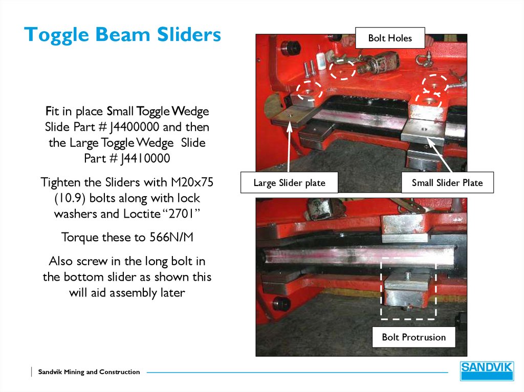
Toggle Beam SlidersBolt Holes
Fit in place Small Toggle Wedge
Slide Part # J4400000 and then
the Large Toggle Wedge Slide
Part # J4410000
Tighten the Sliders with M20x75
(10.9) bolts along with lock
washers and Loctite “2701”
Large Slider plate
Small Slider Plate
Torque these to 566N/M
Also screw in the long bolt in
the bottom slider as shown this
will aid assembly later
Bolt Protrusion
Sandvik Mining and Construction
68. Clamping Rams
Apply Bearing fit to the bearing then press the bearings Part# BT6001 into the clamp rams Part # HR1050 and then hold
in place with Circlip Part # FAW 78 IC
Bearing
BT6001
Ram
HR1050
Circlip
FAW78IC
Sandvik Mining and Construction
69. Clamping Rams
Toggle Seat End PlateJ4360000
Apply anti seize compound to
the shaft of the Toggle seat end
plate Part # J4360000, then fit
shaft assembly Part # HR1050,
hold this in place with Circlip
Part # FAW36XC
There is a left and right hand
side where they will fit so
ensure that the ram is on the
opposite side to the location
pin and the port for the rams
are facing towards the ground
when fitted
Circlip
FAW36XC
Location Pin
Sandvik Mining and Construction
70. Clamping Rams
Mount the clamp rams as shown as there is a left and right hand sideThe oil ports should be pointing down and the location face on the
toggle seat end plate
Tap the ram on to spigot J4520000 and hold in place with Circlip Part #
FAW36XC
Circlip
FAW36XC
Sandvik Mining and Construction
71. Clamp rams
The Toggle seat end plate can nowbe mounted onto the Toggle seat
To do this ensure the caps have
been removed from the Clamp
rams, then extend the ram until the
bolt holes align on the toggle seat.
Ensure the guide locates into the
toggle seat and secure in place with
4 M16x70 (8.8) bolts along with
M16 I Disk lock washers
Torque these bolts to 206 N/M
Sandvik Mining and Construction
72. Adjustment Ram Assembly
Mount the wedge ram basebrackets Part # J4420000 to
the Ram Part # HR1049 with
Pin Part # J443000 and secure
in place with Circlip Part #
FAW38EC
Circlip
Ram base bracket
Wedge Ram Bracket
J4420000
Sandvik Mining and Construction
73. Wedge Ram
Lift and mount the Adjustmentram to the wedge ensuring the
ports of the ram are pointing
towards the back of the crusher
box
Secure in place with 4 M20x100
(12.9) cap screws along with
M20 Disk lock Washers
Torque to 680N/M
Sandvik Mining and Construction
74. Wedge Ram
M24 BoltsLocate the Wedge ram base
brackets Part # J4460000 to the
ram and hold in place with 4
M20x120 (8.8) bolts along with
M20 Disk Lock Washers
Before tightening torque the 3
M24(10.9) bolts to 979 N/M
Then torque the remaining M20
bolts to 403N/M
Ensure when fitting the brackets
that the thickest section of the
bracket is towards the outer face
Sandvik Mining and Construction
75. Mainframe Assembly Lowering the Jaw Stock
Lift the Jawstock assembly using suitable eyebolts and “D” shacklesthen slowly lower down into the mainframe
Ensure that the Jawstock is central as it is lowered and it doesn’t foul
the mainframe sides
Sandvik Mining and Construction
76. Mainframe Assembly Lowering the Jaw Stock
Ensure the bearing housings pass the mainframe and then guide onto thelocation point as shown
Use a bar in the bearing housing fixing hole to line up all of the bolt holes
ready for fixing
Step 1
Sandvik Mining and Construction
Step 2
Step 3
Step 4
77. Mainframe Assembly
With the jawstock in place and the boltholes lined up fit into place M48x180
Bolts (apply anti seize compound to
these bolts) along with Spacers Part #
J4060000
Push the bolts through until they are
flush with the inner mainframe face
Slide into place the bearing housing
location plates Part # J4240000 and
tighten the bolts into these by hand
You will require two people to mount
these in place
Sandvik Mining and Construction
78. Plugs
With the jaw stock in place and the lifting equipmentremoved there are two taped holes in the Jawstock. These
holes will need to be plugged with two M30x60 bolts and 4
hydraulic washers Part # MDBS16
4 hydraulic
washers
Sandvik Mining and Construction
79. Toggle Ram Assembly
Ram HR1090Before fitting the toggle rams
Part # HR1090 you must first
fit link arm bearing Part
BT3009 # & bearing BT6006
Press these bearings into the
ram ensuring that bearing fit
is used
Bearing
BT3009
Hold bearing BT6006 in place
with snap ring FAW78IC
Snap Ring
FAW78IC
Bearing BT6006
Sandvik Mining and Construction
80. Toggle Jaw Bracket
Mount the Ram Assembly tothe L/H and RH Toggle Jaw
Bracket by screwing bearing
BT6006 into the plate
ensuring that you use “loctite
2701” thread lock
Ensure the L/H Plate Part #
J8080000 and the R/H Plate
Part # J8090000 is mounted
to the correct side and the
location pin on the plate is
facing away from the Ram
Sandvik Mining and Construction
81. Toggle Ram Assembly
Lift the toggle ram assembly into position and ensure the correct orientation of the ramassemblies (see below) and secure in place with Circlip Part # FAW36XC
The ram ports should be facing upwards
L/H assembly
R/H assembly
Sandvik Mining and Construction
R/H
assembly
L/H
assembly
82. Toggle Ram Assembly
Remove the blanking caps from the ramas this aids during fitting
Secure to the bottom of the Jawstock
assembly using 4 M16x55 (8.8) bolts
along with M16 disk lock washers
Ensuring that the location pin locates into
the jawstock and tight to 206 N/M
With the assembly tight against the
jawstock tighten bearing BT6006 using a
17mm Hex socket to a toque of 500 N/M
Ensure that the plate is tight up against
the jawstock
Sandvik Mining and Construction
Torque to
500 N/M
83. Toggle Tie Bar
M24bolt andwasher
With the toggle rams in place
you can now mount the
Toggle Plate Tie Bar Part #
J5390000 along with Support
Bush Part # J5370000 hold I
place with an M24 flat washer
and M24x80 bolt
Leave this loose do not
tighten
Ensure they are fitted with
the short side of the tie bar
towards the toggle seat
Sandvik Mining and Construction
Tie Bar
J5390000
Bush J5370000
84. Fitting the Toggle Plate
Before fitting the toggle plate you will need to lift the jaw stock to give youenough room
To do this lower a suitable chain down into the chamber and place the hook
into the bottom of the swing jaw as shown
Now raise the crane until the jaw stock has pivoted around enough
Sandvik Mining and Construction
85. Fitting the Toggle Plate
Place a M16 eye bolt into Toggle PlatePart # J5280000 and then lift into the
jaw box as shown with a suitable
chain
Toggle plate
Lower fully in and then lift so that the
toggle plate is in position on the
cross beam toggle seat
Once in place lift the toggle plate
until the jaw stock toggle seat is
inline. Whilst doing this guide the
Toggle seat tie bars through the
toggle plate. Then lower the jaw stock
down until the toggle plate is
mounted centrally and trapped
between the two seats
Lower the Jawstock fully down and
remove the chain
Sandvik Mining and Construction
Toggle Tie
Bar
Jaw Stock Toggle
Seat
86. Toggle Plate Tie Bar
With the toggle plate in place attached the Toggle Tie bar on tothe “Y” bracket with a M24x80 (10.9) bolt along with M24 flat
washer and Spacers Bush Part # J5370000
Then torque to 979 N/M on all 4 of the Tie Bar bolts
Sandvik Mining and Construction
87. Tie Bar
With the jaw stock toggle plate inposition Tie Bar Part # J4540000
can be lifted in place though the
mainframe side plates and the
Jawstock. Ensure that there is an
equal amount of thread exposed on
either side of the side plates
Tie bar J4540000
Apply anti seize compound around
the Side Plate Tie bar Outer Bush
Part # J4560000 then fit into place
on both sides of the Tie Bar
Apply anti seize compound to the
thread of the tie bar and place M64
nut loosely on either side
Bush J4560000
Sandvik Mining and Construction
88. Tie Bar Spacers
Spacer J4550000On both sides there is a gap
between the shoulder of the
tie bar and the side plate.
This is where you mount Side
Plate Spacer J4550000. Secure
in place with 2 M12x90 (8.8)
along with M12 flat washers
Location of spacer
Torque to 84 N/M
First mount the spacer on the
drive side
Tighten in place
Sandvik Mining and Construction
89. Tie Bar Spacer
When fitting the Tie barSpacer to the None drive side
it may be necessary to spread
the box slightly to get the
spacer to fit
Do this place a Porta Power
jack as shown across the box
and pressurise
If the spacer will not fit then
refer to the Sandvik design
team
Sandvik Mining and Construction
Porta Power
90. Tie Bar Spacers
Spacer J4550000The None drive side Tie bar
spacer J4550000 can now be
fitted and secure in place with
2 M12x90 (8.8) along with
M12 flat washers
Location of spacer
Torque these to 84 N/M
Tighten in place
Sandvik Mining and Construction
91. Tightening Torque
You can now tighten the 12 cartridge boltsup to 6045N/M Wet (anti seize compound
fitted) (8060N/M Dry)
Weld the locking tabs to the bolt heads.
(Ensure the bearing cover plate is fitted to
protect the bearing)
The Tie Bar can be now be torqued up to
11837N/M
Tie Bar
Sandvik Mining and Construction
92. Float Check
With the jaw box torqued up remove thecartridge cover plate from the None drive
side and check the following measurements
The distance from the bearing housing to
the bearing outer race
Ensure this measurement is noted as this
will tell you where the bearing has floated
across to during the mainframe being
torque up
It should be approximately ½ the distance
as measured earlier before mounting
The cover plate can then be put back using
Loctite “2701” and then torque to 566N/M
(10.9 grade bolts)
Sandvik Mining and Construction
93. Flywheel Keys
The flywheels are keyed in placeThe key Part # J4220000 should be
tested in the shaft and the
corresponding flywheel Part #
J4200000
File the key so it fits into the shaft
and flywheel if necessary
Sandvik Mining and Construction
94. Flywheels
Before fitting flywheel Part #J4200000 clean and de-burr
Measure the inner bore diameter
it should be between 209.90mm
to 290.95mm
If not please refer to the Sandvik
design team for further assistance
Fill the labyrinth groove in the
bearing end cover with grease
Sandvik Mining and Construction
95. Flywheels
Before mounting the flywheelto the shaft smear the shaft in
anti seize compound
Then lift the flywheel using
suitable lifting equipment and
slowly slide onto the shaft
Ensuring the flywheel is tight
up and fit the key.
Now fit in place end cap Part
# J4230000 ensuring the
arrow is pointing towards the
key
Secure in place with 3 (10.9)
M30 x 70 bolts applied with
Loctite 2701 and torque to
1935N/M
Repeat for the other side
Sandvik Mining and Construction