


Similar presentations:


")

The Bailey : The Amazing, All-Purpose Bridge
1.
The Bailey :The Amazing, All-Purpose Bridge
by Larry D. Roberts
World War II was the first great war of mobility . Motorized and mechanized armies covered hundreds of miles in
large-scale offenses and counteroffenses. In those theaters
with rugged terrain or numerous river systems, combat engineers built thousands of temporary and semipermanent
bridges to maintain the momentum of the battle and ensure
the logistical support of the fighting forces. For the Allied
nations, the Bailey bridge provided a degree of versatility and
utility unparalleled in combat engineering. Soldiers of all
Allied nations used the Bailey in every theater of the war.
In the first year of the European war, British engineers
were faced with the problem of inadequate bridging for certain armored equipment. The heaviest class of bridge could
carry 19 tons, but the Matilda tank, fielded in 1939, weighed
23 tons. The first reaction was to modify existing material
to accommodate the increased load requirements . Engineers
modified the box girder and ponton bridges to take a 24-ton
load . In a short time, improved Matildas exceeded that limit
by 2 tons. However, engineers believed that the existing
material could handle the 26-ton requirement. The advent
of the Churchill, a tank of approximately 40 tons, was too
much. The British were forced to return to the drawing board.
Donald Coleman Bailey, chief designer at the British
Experimental Bridging Establishment, had toyed with the
idea of a bridge built out of truss panels, rather than box
girders. One day, after the failure of a new piece of equipment during testing, Bailey and his associates discussed his
idea, sketching the panels on the back of an envelope. The
idea seemed to have sufficient merit, and Bailey and his
colleagues received permission to proceed with further testing. From the beginning, the project was a team effort.
Major H. A. T. Jarrett-Kerr, Royal Engineers, did much of the
detailed work on Bailey's design . Ralph Freeman, the designer of the Sidney Harbour bridge, also contributed.
2.
182Builders and Fighters
The engineers decided that in designing and producing
a new bridge they had the opportunity to correct many of
the problems which had plagued similar projects in the past.
To this end, they developed a set of criteria for the new bridge.
First, the girder and deck system had to be capable of being
strengthened at will and in place. This would allow flexibility
in handling various vehicles. Second, all parts had to be made
of readily available materials. Special steels were sometimes
impossible to acquire during the war. Third, any engineering firm had to be capable of building the bridge. In the past
some of the designs were so complex that only a few companies were able to produce the material. Similarly, close
manufacturing tolerances would be avoided if possible. This
would also simplify production by a variety of companies.
British floating Bailey bridge on Mark VI pontons.
(Engineer School Library)
The engineers considered the realities of field use as well.
They wanted the bridge to be transportable in the standard
3-ton lorry. Special purpose transportation vehicles compounded the problem of movement, maintenance, and supply.
To eliminate the need for construction cranes and hoists, no
part of the bridge would be heavier than a six-man load. In
order to facilitate launching, the designers specified that the
underside of the girders were to be kept smooth. A smooth
under surface would also allow engineers to use the Bailey
on pontons.
3.
The Bailey: The Amazing, All-Purpose Bridge183
The bridge that finally emerged met virtually all of the
designers' specifications . The central piece of the bridge was
the Bailey panel . This was a welded truss, with vertical and
diagonal supports, 10 feet long by 5 feet high . Each panel
weighed 600 pounds . Panels were attached end to end with
pins creating a multiple truss girder. The panels could be
stacked three high and placed side by side. This resulted in
such variations as the double-double Bailey (two panels side
by side and two panels high) and the double-triple Bailey (two
panels wide and three panels high). This meant that bridge
components could be added to increase the load capacity
of the bridge. For example, a single-single Bailey spanning
100 feet could support a 10-ton load . A double-single across
the same span could support 28 tons. A 100-foot triple-single
bridge could handle 45 tons, and a similar span double-double
Bailey could support loads safely at 75 tons. In addition, the
panels saved up to 40 percent in transportation space, were
easy to handle, provided flexibility in construction, and were
adaptable to float bridges.
The floor system of the Bailey was conventional . It consisted of floor beams placed at 5-foot intervals, with steel
stringers, wood flooring, and wood ribands (curves) . In time,
steel ribands replaced the wooden material because tank
tracks damaged the wooden components. The floor beams or
transoms could be doubled, giving reinforcement to the floor.
This also allowed construction of a two-lane bridge where
the center girder was larger than those on the outside of the
traffic lanes.
In a comparatively short tune, a bridge was available for
testing, and designers decided to load the structure to failure
to determine its actual capabilities . Some of the loading
techniques were unusual to say the least. On one occasion,
a World War I vintage tank was placed on the center of the
span. A timber platform was built on top of the tank, and
by means of a ramp, two more old tanks were "poised" on
top of the first. The lower tank was then filled with pig iron,
and several additional tons of material were placed on the
span wherever there was room. The bridge held. Engineers
ultimately loaded the bridge to failure, the top cord of the
center panels finally buckling These failure tests did produce
4.
Builders and Fighters184
tables which units could use in deciding what form of Bailey
they were to build for a given situation.
The sense of urgency which dominated the design team
and the cooperation it received from the British manufacturing establishment resulted in one of the shortest designto-production periods of the war. It generally took a full year
during the war for material to get from the drawing board
to troops; however, design and production of the bridge proceeded concurrently and a pilot model was ready for test in
less than five months. Production was under way in approximately seven months, and troops began receiving the bridge
three months later. Therefore, by December 1941, British combat engineers had solved their problems of bridging for the
new armored vehicles. By the time American engineers began
wrestling with new bridge requirements for their growing
armored forces, British combat engineer units had confirmed
the value of the Bailey in actual operations.
The American side of the Bailey bridge story began in
May 1940 when the U.S. Army’s Ordnance Department announced that the existing 15-ton medium tank was obsolete.
Ordnance plans called for a newer medium tank of 25 tons
and a heavy tank of 50 to 60 tons. Like the British, the
American engineers’ first response was to modify existing
Engineers lift the bascule span of a class 70 Bailey bridge.
(Engineer School Library)
5.
The Bailey. The Amazing, All-Purpose Bridge1$5
equipment to the extent possible. Ponton boats could be
enlarged ; the H-10 and the H-20 fixed bridges could be
strengthened by adding girders and shortening spans; but
these solutions tended to add weight and material to the
bridge train. In addition, it would take longer to build the
heavy girder bridges such as the H-10 and the H-20 . The
advent of pneumatic floats solved some of the problem of
weight and transportation. These floats were lighter and more
easily moved than the ponton boats; however, there was no
corresponding easy solution for fixed bridging.
In early 1941, the Chief of Engineers directed the Engineer Board, the Corps research and development organization, to investigate heavier bridging, both fixed and floating.
One project involved the design of H-30 and H-50 bridging
which would ultimately support 30- and 50-ton tank loads
across a 150-foot span. In August 1941, the Chief of Engineers
also directed the Engineer Board to investigate the "modification of the British Bailey Panel Bridge to fit standard
U.S. sections."
Engineers working on the now formally designated Project
SP 341, Portable Steel Bridges for Heavy Loads, considered
five factors. Bridge types to be adopted would be held to a
minimum, not more than two, preferably one. Weight was to
be held to a practicable minimum. The design should involve
maximum simplicity of construction and provide for a clear
span of 150 feet. Finally, the bridge material should be transportable on standard military vehicles. Much like the British
team which developed the Bailey, American engineers were
concerned with simplicity, weight, and transportability.
Several existing American bridges met one or two of these
criteria, but none met all of the requirements.
Because the staff of the Engfneer Board's Bridge Branch
was already overtaxed, the board decided to assign the design
requirement for "a bridge of the Bailey type" to the engineer
ing firm of Sverdrup and Parcel of St. Louis, Missouri . The
civilian' engineers were to modify the Bailey design to compensato for the differences in British and American rolling
mill techniques . Aware of the potential benefits of having a
bridge whose compone4ts were totally interchangeable with
the British bridge, the" hoard was sensitive to any unnecessary. design changes. When Sverdrup and Parcel submitted
J
6.
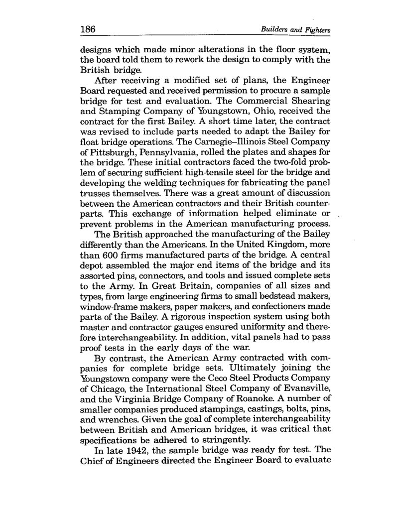
186Builders and Fighters
designs which made minor alterations in the floor system,
the board told them to rework the design to comply with the
British bridge.
After receiving a modified set of plans, the Engineer
Board requested and received permission to procure a sample
bridge for test and evaluation . The Commercial Shearing
and Stamping Company of Youngstown, Ohio, received the
contract for the first Bailey. A short time later, the contract
was revised to include parts needed to adapt the Bailey for
float bridge operations. The Carnegie-Illinois Steel Company
of Pittsburgh, Pennsylvania, rolled the plates and shapes for
the bridge. These initial contractors faced the two-fold problem of securing sufficient high-tensile steel for the bridge and
developing the welding techniques for fabricating the panel
trusses themselves . There was a great amount of discussion
between the American contractors and their British counterparts. This exchange of information helped eliminate or
prevent problems in the American manufacturing process.
The British approached the manufacturing of the Bailey
differently than the Americans. In the United Kingdom, more
than 600 firms manufactured parts of the bridge. A central
depot assembled the major end items of the bridge and its
assorted pins, connectors, and tools and issued complete sets
to the Army. In Great Britain, companies of all sizes and
types, from large engineering firms to small bedstead makers,
window-frame makers, paper makers, and confectioners made
parts of the Bailey. A rigorous inspection system using both
master and contractor gauges ensured uniformity and therefore interchangeability. In addition, vital panels had to pass
proof tests in the early days of the war.
By contrast, the American Army contracted with companies for complete bridge sets. Ultimately joining the
Youngstown company were the Ceco Steel Products Company
of Chicago, the International Steel Company of Evansville,
and the Virginia Bridge Company of Roanoke. A number of
smaller companies produced stampings, castings, bolts, pins,
and wrenches. Given the goal of complete interchangeability
between British and American bridges, it was critical that
specifications be adhered to stringently.
In late 1942, the sample bridge was ready for test. The
Chief of Engineers directed the Engineer Board to evaluate
7.
The Bailey: The Amazing, All-Purpose Bridge187
Traffic crossing a class 70 panel bridge with a pedestrian walk.
(Engineer School Library)
the Bailey primarily as a fixed bridge replacement for the
H-10 and H-20 bridges. Later, the board was to test both
the Bailey and the H-10 bridge on the 25-ton pontons. The
fixed bridge test took place at Fort Belvoir with the float
bridge test scheduled for the Yuma Test Branch in the Southwest. The Engineer Bridge Branch submitted its fixed bridge
test results on 5 December 1942.
The Bailey met many of the initial requirements described
in the “Portable Steel Bridges for Heavy Loads” project. The
British bridge possessed the requisite flexibility to serve as
the single, multipurpose bridge. The Bailey could be reinforced in place without dismantling. Its heaviest component
was only 600 pounds, compared with 1,732 pounds for the
H-20 component and 1,132 pounds for the H-10. Finally,
drivers expressed more confidence in the Bailey because the
panels rising on both sides of the roadway gave them a
greater sense of security than the other bridges. The report
also pointed out the Bailey’s deficiencies. It required more
parts to assemble than did the other bridges, and the roadway could not be widened without redesign. A major liability
was the need for precise cutting, welding, and fabrication. The
Bridging Branch recommended the retention of both the
H-10 and the H-20 for all but the European theater where
the Bailey could be used by Allied nations.
8.
188Builders and Fighters
The recommendations passed to the Chief of Engineers
from the Engineer Board did not, however, correspond with
the suggestions of the Bridging Branch. There was sufficient
support for the Bailey on the board to change one of the
recommendations . The board recommended that the H-10
be retained, following the suggestions of the Bridging Branch .
However, the board recommended that the panel bridge
(Bailey type) be procured in place of the H-20 bridge. The
flexibility of the Bailey and the possibility that it could serve
both American and British engineers overcame the concerns
about the close tolerances and exact measurements required
during the manufacturing process.
It is possible that some American engineers were not
overly concerned about the precision production challenges
posed by the Bailey. The British had attained standardization
for component parts in spite of the fact that hundreds of companies made parts of the bridge. The British ensured their
interchangeability through the use of fabricator gauges and
a single master gauge. The use of those instruments precluded acceptance of parts which did not meet specifications .
Early in the fabrication phase for the test bridge, American engineers borrowed a set of gauges from the Canadians.
These gauges had been sent to Canada from England as part
of an education program on manufacturing the bridge. However, the Engineer Board recognized that, in time, American
manufacturers would have to have their own set of fabricator
gauges. A master set would be used to ensure the accuracy
of the fabricator gauges. After some hesitation, the Chief of
Engineers approved the procurement of 25 sets of Bailey
bridge gauges for the British army and six ponton-coupling
gauges for use with the floating Bailey equipment. The Chief
of Engineers approved the production of these gauges for the
British in consideration of their cooperation in supplying
the original master gauges via Canada. It was not until
September 1942 that the engineers found two firms-the
Industrial Tool and Die Works of Minneapolis and the
R. Krasberg and Sons Company of Chicago-to produce the
gauges . The contractors completed production of these instruments in January 1943 .
As bridge sets became available, the Engineer Board
intensified its testing. In an effort to develop procedures for
9.
The Bailey: The Amazing, All-Purpose Bridge189
employing the bridge while also evaluating its capabilities,
the board conducted troop tests with the 31st Engineer Combat Regiment at Fort Belvoir. The 31st erected a number of
bridges, both fixed and floating, with the Bailey panels. These
troop tests confirmed the structural soundness and flexibility
of the bridge. Board members concluded that the British capacity ratings for various spans were conservative, but did
not recommend new classifications in their report to the
Chief of Engineers. The success of the Bailey as a float bridge
was significant in light of problems with the steel treadway
float bridge which occurred in the fall of 1942.
In four separate instances-two at the Desert Training
Center, one at Fort Benning, and one at the Tennessee
maneuvers-- tanks crossing steel treadway float bridges had
slid into the water. In each instance, excessive weight or
off-centered loading caused the bridge to twist and floats to
come out from under the treadway. Seven soldiers were killed
in these incidents. Although the armored force insisted that
the bridge was acceptable, engineers moved to improve the
safety of the treadway and increase the size of the floats.
These incidents also increased interest in the Bailey’s capabilities as a float bridge.
Assembly of a floating Bailey bridge.
(Engineer School Library)
Confirmation of the 31st Engineers’ success with the
Bailey as a float bridge came with the Tennessee maneuvers
10.
190Builders and Fighters
of 1943. The 551st Engineer Heavy Ponton Battalion constructed a 590-foot floating Bailey at Rome Ferry, Tennessee,
during the second phase of the maneuvers. A large part of
an armored division crossed the bridge shortly after its completion. Engineers monitored the bridge, which was under
constant use for approximately one week. Engineers found
that the Bailey did not require significant additional transportation assets when used with the 25-ton ponton . After the
maneuvers were concluded, the 551st considered the floating
panel bridge (Bailey type) superior to any standard ponton
bridge. The battalion's report stated that the bridge was more
stable and would carry a heavier traffic volume in given time.
Maintenance problems were fewer and, as in earlier tests,
drivers were more confident crossing the through-type bridge.
Although tests to officially confirm the Bailey's capabilities as a float bridge were not concluded until the end
of 1943, troop tests in the United States and combat use in
Europe had already established the bridge's amazing potential . Ironically, these same tests identified a problem with
the production of the Bailey. The problem went to the core
of the concept of an interchangeable bridge for both the
British and the Americans.
During the troop tests with the 31st Engineer Regiment,
board members found that some of the panels were off-size .
The cause was faulty fabrication. These components had to
be altered by grinding or spreading to fit with the other
parts of the set. In theory, the fabricator's gauges should have
detected these panels before they were issued to troops. In
October 1943, the board decided to recheck the gauges to
ensure that they were still accurate . The engineers again
borrowed the Canadian gauges to use as a master. The comparison revealed that many of the gauges had been damaged
in use and others were not accurate due to poor quality
workmanship. This necessitated a thorough reconditioning
and repair of the American master gauge and the fabricator
sets as well. The engineers then instituted a program whereby the gauges were periodically reconditioned through a
schedule that would not interfere with the manufacturing
of the bridge sets.
The damage to the concept of interchangeability had
already been done. It was not until August 1944 that
11.
The Bailey. The Amazing, All-Purpose Bridge191
engineers had gauges that corresponded in tolerances to those
of the British. As a result, the 850 American-made Bailey
bridges acquired in 1944 had to be segregated from the
British bridges because the components were not interchangeable. Tests conducted by the Australians on American-built
Baileys revealed that 75 percent of the panels were not interchangeable even with each other. After the war was over,
the British returned the 25 gauge sets the Chief of Engineers sent them in 1942 because they were of such poor
quality that they were practically worthless . The system of
mass production and quality control applied to making
the Bailey in the United States failed within the context
of interchangeability.
The failure of precision production did not keep the Bailey
from becoming the most versatile military bridge in history.
Its greatest use was in Sicily and Italy where German demoli
tions created hundreds of river and dry land obstacles . In a
20-month period in Italy, the American Fifth and British
Eighth Armies constructed more than 3,000 fixed Bailey
bridges to cross different streams. The combined lengths
of these bridges was 55 miles, with an average length of
100 feet. Engineers found that the panels could also be used
to construct piers for bridges. The Eighth Army built one
Bailey using panel crib piers of 70 feet. When Germans
foolishly dropped bridge spans but spared the piers, Baileys
were used to restore mobility quickly. For example the
Germans dropped 19 spans of the Sangro River bridge, but
left 14 piers standing. British engineers built a 1,126-foot
Bailey on the standing piers. The Bailey was also adapted
as a suspension bridge in Italy. One such structure over the
Volturno River carried 240,000 vehicles in eight months.
In northwest Europe, the Bailey was used primarily as
a fixed tactical or line of communications bridge. For the war
of movement across northern France, most divisions relied
on steel treadway floating bridges. These were much faster
to use and easier to transport than the Bailey. The Third
Army erected 53 treadway bridges with a total footage of
20,166 feet compared with 11 floating Baileys with 9,380 feet
aggregate length . General George Patton's command built
almost 27,000 feet of fixed Bailey bridging compared to approximately 9,800 feet of fixed treadway bridging During the
12.
192Builders and Fighters
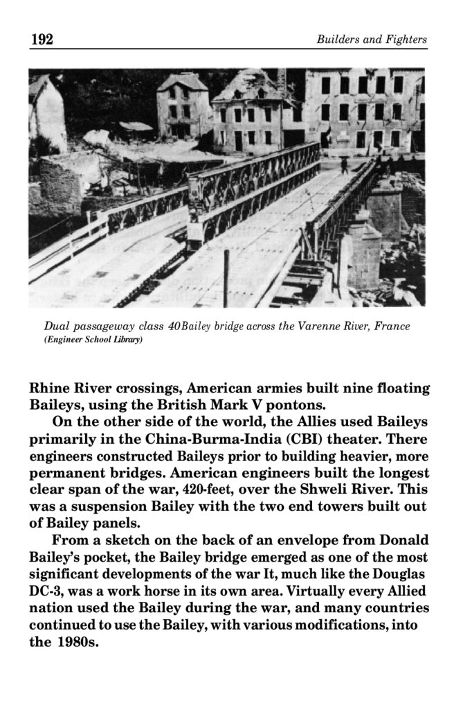
Dual passageway class 40 Bailey bridge across the Varenne River, France
(Engineer School Library)
Rhine River crossings, American armies built nine floating
Baileys, using the British Mark V pontons.
On the other side of the world, the Allies used Baileys
primarily in the China-Burma-India (CBI) theater. There
engineers constructed Baileys prior to building heavier, more
permanent bridges. American engineers built the longest
clear span of the war, 420-feet, over the Shweli River. This
was a suspension Bailey with the two end towers built out
of Bailey panels.
From a sketch on the back of an envelope from Donald
Bailey’s pocket, the Bailey bridge emerged as one of the most
significant developments of the war It, much like the Douglas
DC-3, was a work horse in its own area. Virtually every Allied
nation used the Bailey during the war, and many countries
continued to use the Bailey, with various modifications, into
the 1980s.
13.
The Bailey. The Amazing, All-Purpose BridgeSources for Further Reading
193
Articles for additional readings on the Bailey bridge
include : LTC S. A. Stewart, "The Conception of the Bailey
Bridge," The Royal Engineers Journal LVIII (Dec. 1944),
pp. 237-43; R. S. Bishop and K. S. Frazier, "Manufacturing
the Bailey Bridge;' Military Engineer, XXXVII (June 1945),
pp. 219-222 ; John A. Thierry, "The Bailey Bridge," Military
Engineer, XXXVIII (Mar. 1946), pp. 96-102 ; LT Richard G.
Webb, "Military Construction of the Bailey Bridge," Military
Engineer, 55 (Jan-Feb. 1963), pp. 28-30; and LTC Bruce W.
Reagan, "Sir Donald Bailey's Little Gem," Journal of the
Institute of Royal Engineers (Dec. 1984), pp. 269-271 .