


Similar presentations:


Evaluation of bailey bridge at arundu
1.
CONSTRUCTION CONTROL SERVICES CORPORATIONPESHAWAR
EVALUATION OF BAILEY BRIDGE
AT
ARUNDU
FINAL REPORT (PHASE-1)
PROJECT REPORT/DOCUMENT VOL.JE
SEPTEMBER, 1990.
ASSOCIATED CONSULTING
ENGINEERS ACE (PVT) LTD,
HIGHWAY -5 STRUCTURE DIVISION: 22-C/L, GULBERG-III LAHORE.11
1-C/2, M.M.ALAM ROAD GULBERG-III, LAHORE 11. PAKISTAN
10-BANGLORE TOWN SHAHREA FAISAL KARACHI 8.
ISLAMABAD-MAKKAH-RIYADH-ABUDHABI-TRIPOLI-KANO-TEHRAN-KUALALUMPUR
2.
IASSOCIATED CONSULTING ENGINEERS ACE (PRIVATE) LTD.
FAX
HIGHWAY & STRUCTURE DIVISION
22-C/L, QULBERQ 3, LAHORE 54660
. arwro
JJJJ
TELEPHONE
: 851064-850155
REF. NO..
The Chief of Party,
Construction Control Services
Corporation (CCSC),
Peshawar.
Subject:
DATE
S
..?.P*?.m.^.?r.,..2..T..<..J..?..?.°...
EVALUATION OF BAILEY BRIDGE AT ARUNDU
PIMAL REWftt (PHASE -IT
--
t
Reference:
Your letter dated September 25, 1990
Dear Sir,
Thank you very much for according approval to the subject report through
your letter under reference.
As desired, we are enclosing herewith Seven (7) copies of the Final Report
(Phase-l) after incorporating the "Summary Report" on the ACE stationery
as required by CCSC.
This completes all our assignment which is limited upto Phase-l only of the
Agreement.
Thanking you and assuring you of our best professional services,
You^s faithfully,
id Iqbal)
nager
Encl:
As above
SMH/SSI/sf
Ctfportl. Ofllct : 43-D, KDA SCHEME NO. 1, KARACHL8, PAKISTAN. FAX: 43M79 TELE: 430254 TELEX: 24688 PACE PK. CABLE: CONSULTANT __
Bftnchw: LAHORE -ISLAMABAD- IRAN- MALAYSIA -SAUDI ARABIA- NIGERIA- LIBYA- UNITED ARAB EMIRATES
S
3.
ASSOCIATED CONSULTING ENGINEERS ACE (PRIVATE) LTD.HIGHWAY & STRUCTURE DIVISION
FAX
TELEX
CABLE
TELEPHONE
22-C/L, QULBERQ3, LAHORE 54660
: 870970
:44304PACELPK.
: BRACE LAHORE.
:S51004450155
REF. NO..
DATE.
July 15, 1990
STATEMENT*
I, S. Manzer Husaln, Senior Technical Director, state that the
contents of this report are true and accurate, and has been
accomplished in accordance with the applicable, recognized standards
and metiatfcls. I accept professional responsibility
therefore.
(S. MANZEK HUSAIN)
SENIOR TECHNICAL DIRECTOR
For and on behalf of
•Associated Consulting Engineers ACE (Pvt) Ltd. Lahore
This statement Is furnished under Clause V-h of Section
A-III of the Contract Agreement
Ctrpornle Office : 43-D, KDA SCHEME NO. 1, KARACHI 8, PAKISTAN. FAX: 436679 TELE; 430254 TELEX: 2-1608 PACE PK. CABLE: CONSULTANT
Bf«nchiS ! LAHORE • ISLAMABAD • IRAN - MALAYSIA • SAUDI ARABIA • NIGERIA - LIBYA • UNITED ARAB EMIRATES
_
/
4.
MBI.E01-
UCJN J EN 18
PART - 1
MAIN
SUMMARY
REPORT
CHAPTER-i
1.1
1.2
I. .3
1.1
1.5
1.6
INIRUUUCTJUN
Background
Consultancy ngref?ment
Scope of Services
Panel of Experts
Format of the report
References
CHAPTER-2
2.1
2.1..1
2.1.2
2.1.;$
2.1.4
2.2
2.3
2. "3.1
2.3.2
2.3.3 .
2.3..4
2.3.5
2.3.6
2.4
2.5
2.6
2.7
2./.1
2.7.2
CUMPUTER ANALYSES
Preamble
Description of the Structure
Modelling of the Structure
Input Parameters
Uutput and Forces
Key Elevation of Bridcji?
Input parameters
Programme
Uutput file
Plane of Analysis
Loading Conditions
Fixity Conditions
Member Properties
Reference Figures
Deflections
Member Forces
Discussions
Observed Deflections
Limitations of computer analyses
CHAPTER-3
3.1
3.2
'3.3
3.4
3.4.1
3.4.2
REPORT
LOAD TESTING OF BRIDGE PANELS
Preamble
Intent/Purpose of the Study
Panel Testing
(Test No.i) single panel testing
Testing Arrangements
Supports and lateral bracing provided in the process of
testing
(i)
5.
3.1.33.4.1
3.5
.i . 5 . J
3.5.2
3.5.4
3.6
Load]ng
S t r a i n and D e f l e t Mori Hr'<3r>ui <»IHPM I
( l e s t No./;) Compound t-crsLmq o I I wo
I en tiny Arrangements
Supports and l a t e r a l b i a c m q
Loading process and pane? I beh
Strain and D e f i e d ion Mpastii einen t
Discussion
CHAPTER-4
Visit to the Site
Coupon Removal
Repairs of panels
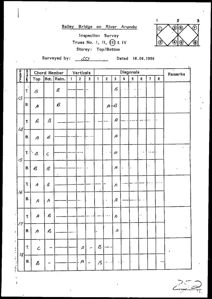
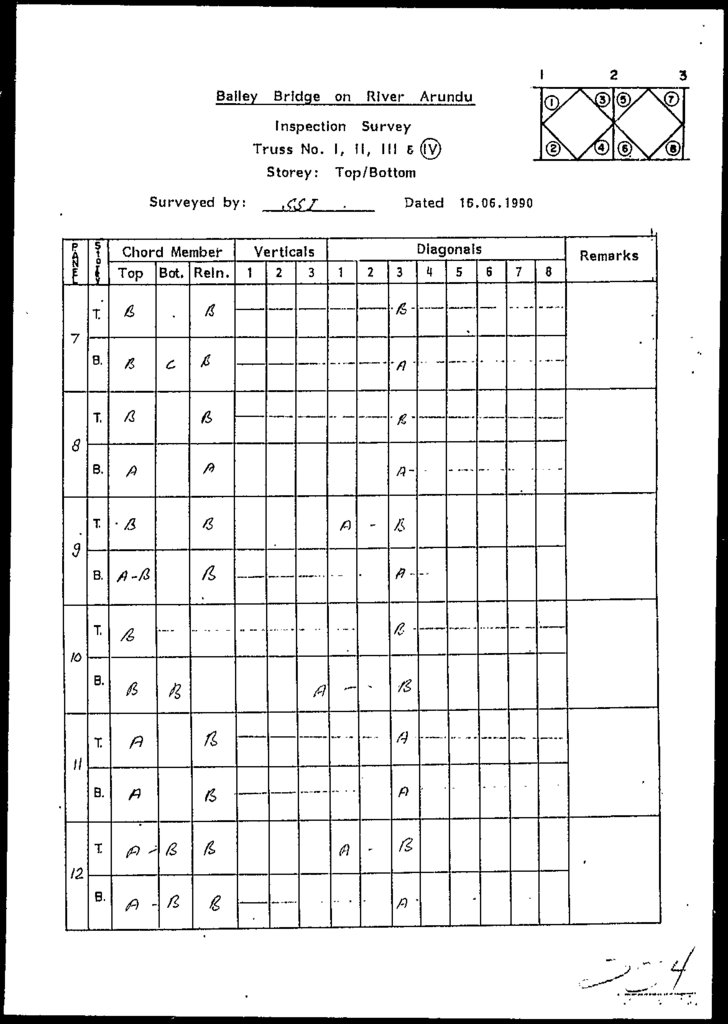
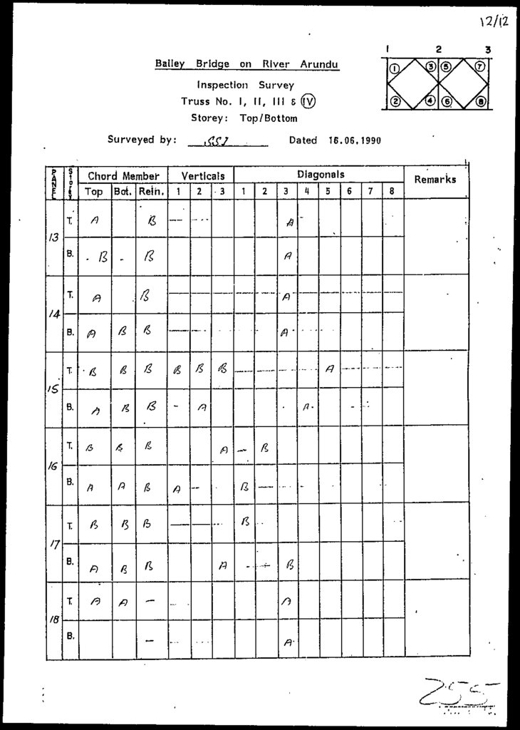
Condition Survey
Observations during Inspection
Comments on Observations
4.1
4.2
4.3
4.4
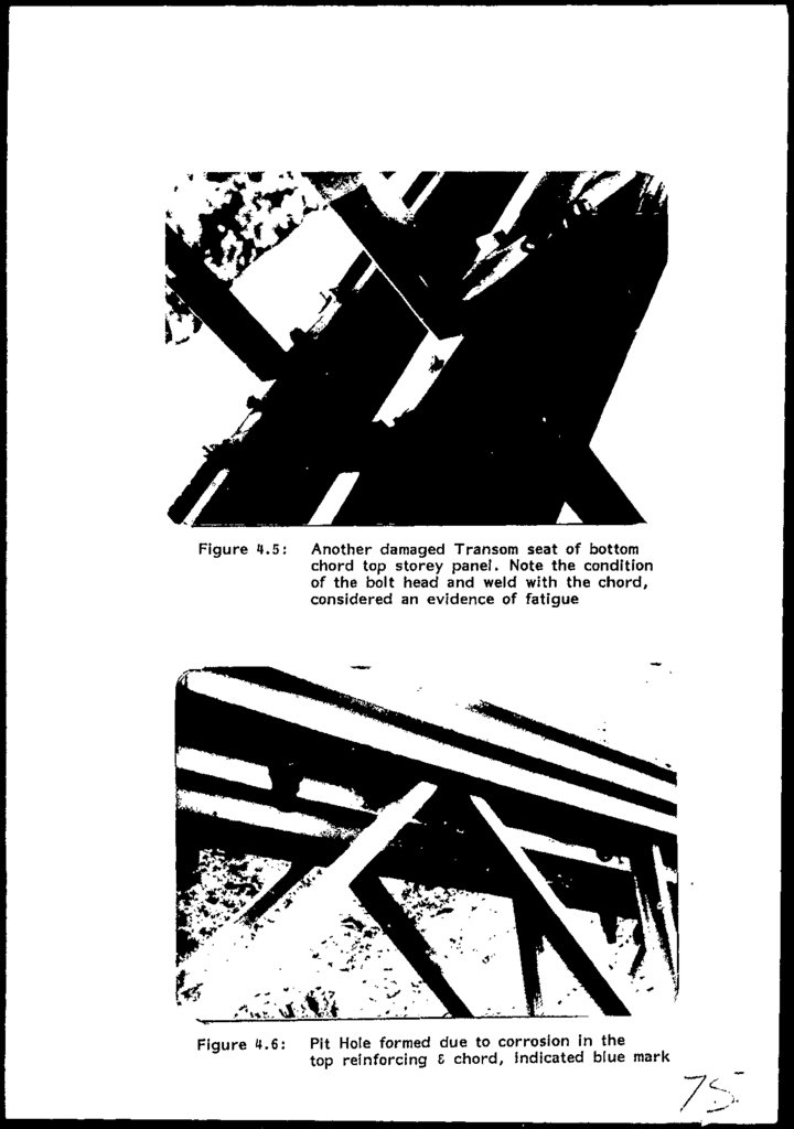
4.5
4.6
CHAPTER-5
5.1
5.2
5.3
5.4 .
5.4.1
5.4.2
5.4.3
5.4.4
5.4.5
5.5
CHEMICAL AND TENSION TESTING
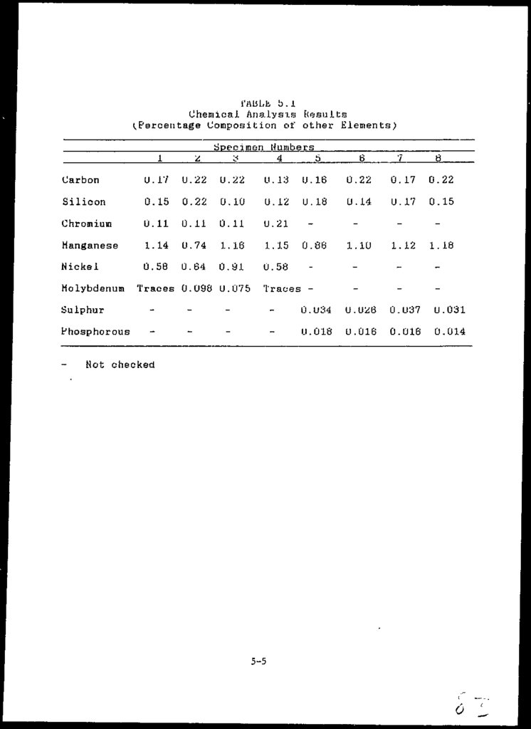
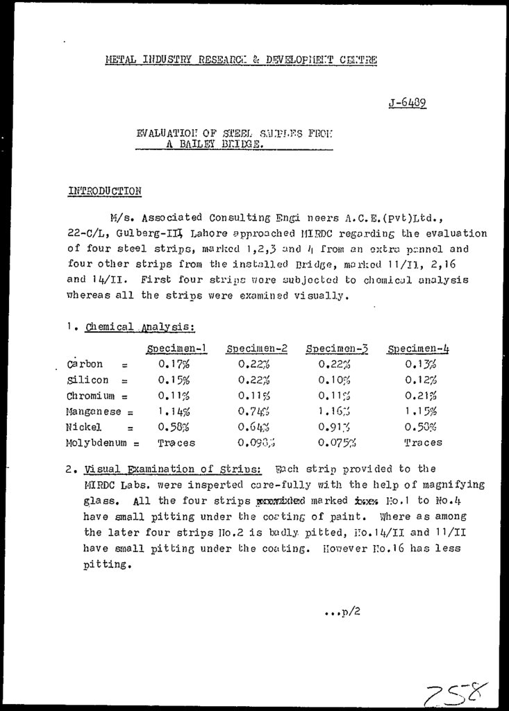
Chemical Testing
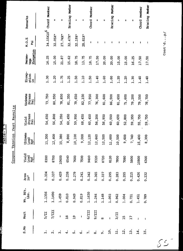
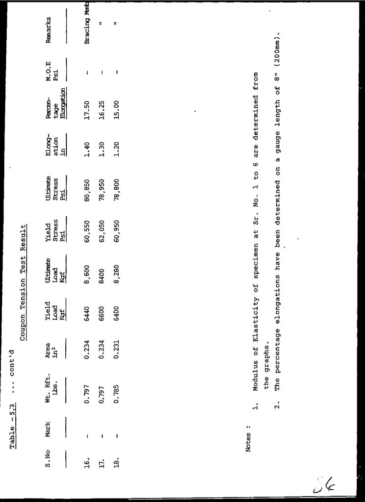
Coupon Testing
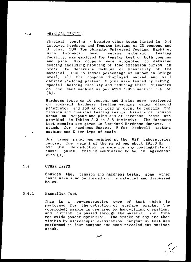
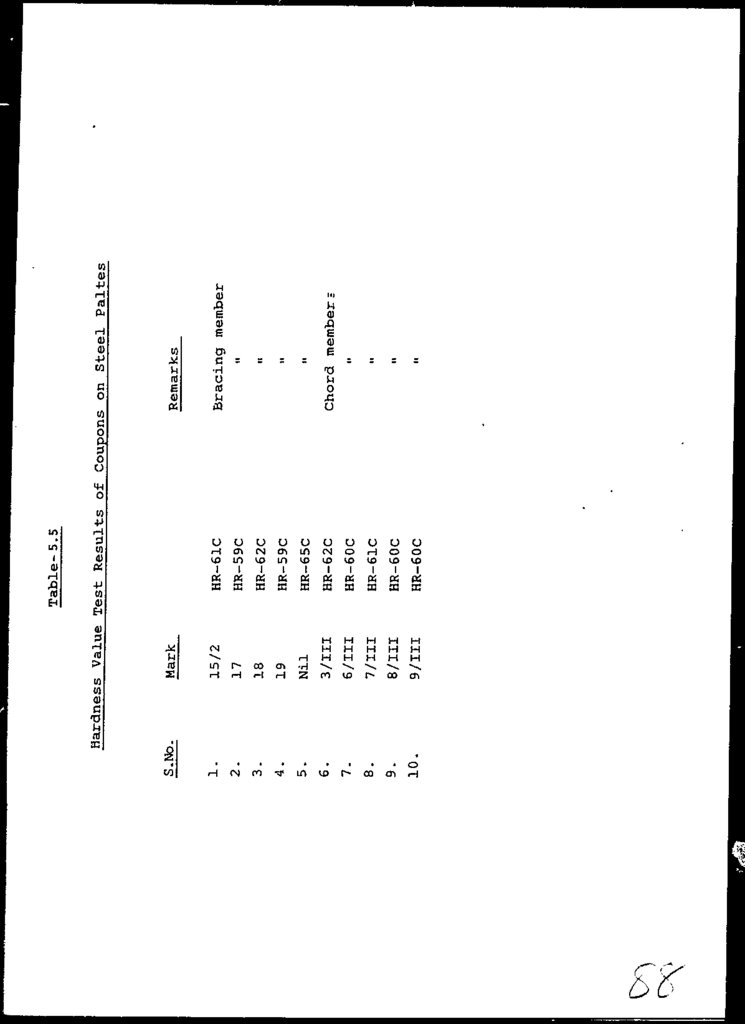
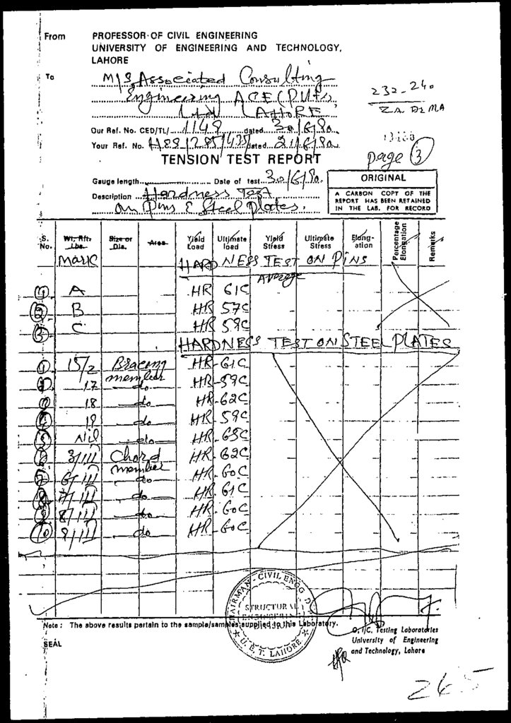
Physical Testing
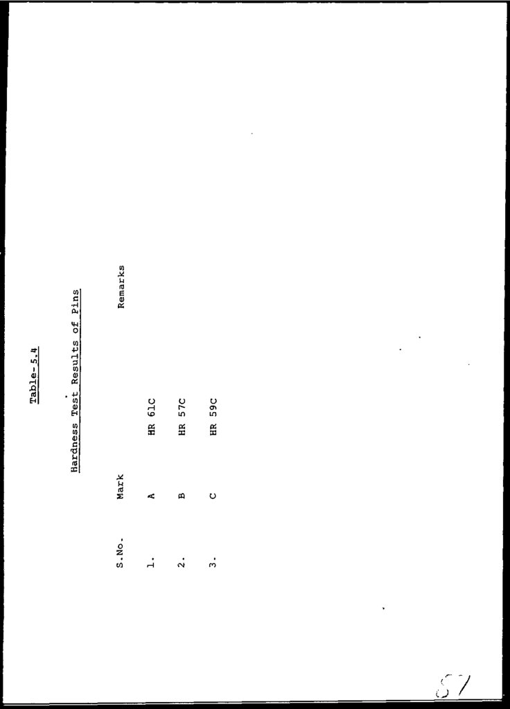
Cither Tests
Magnaflux lest
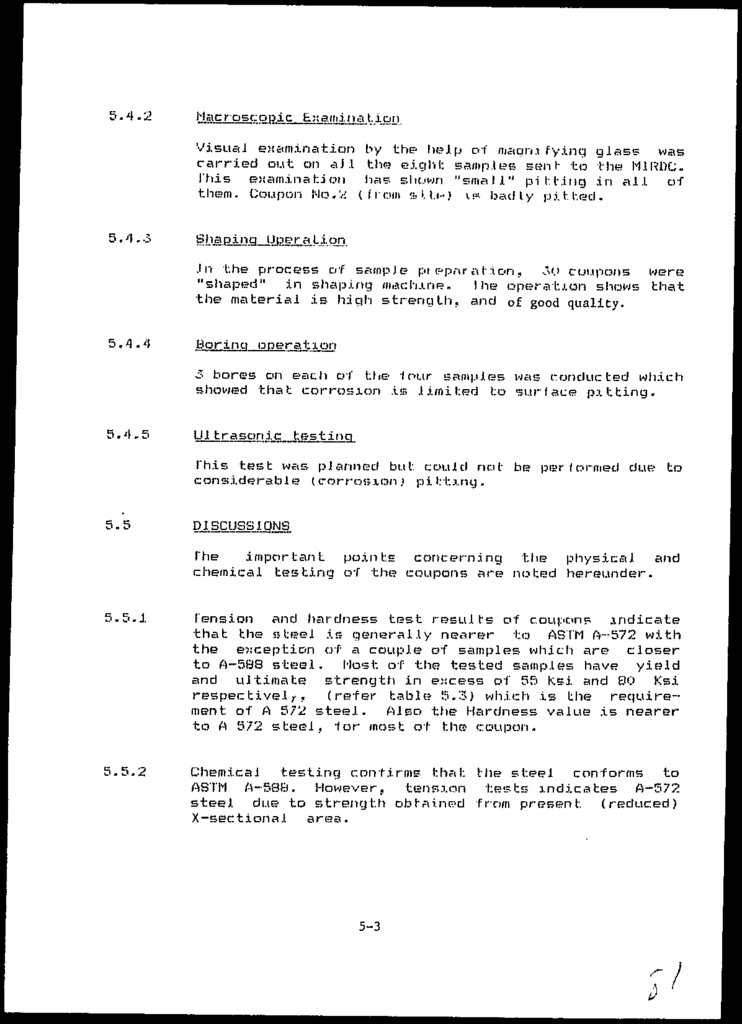
Macroscopic Examination
Shaping operation
Boring operation
Ultrasonic Testing
Discussions
CHAPTER-6
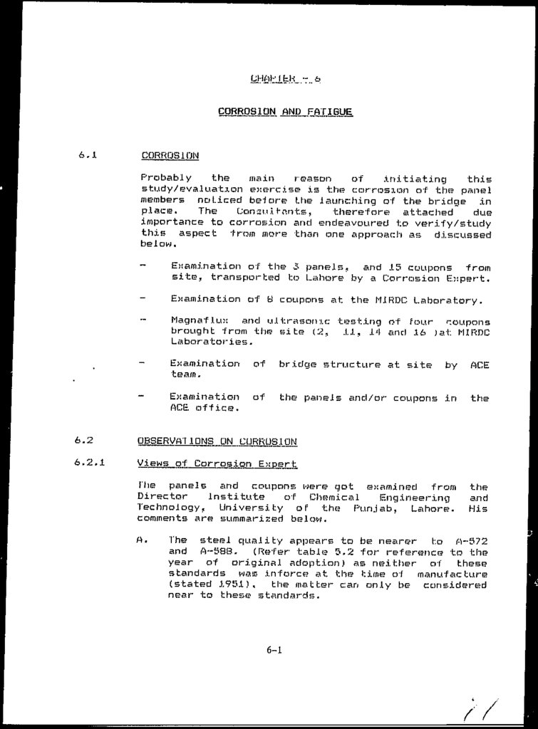
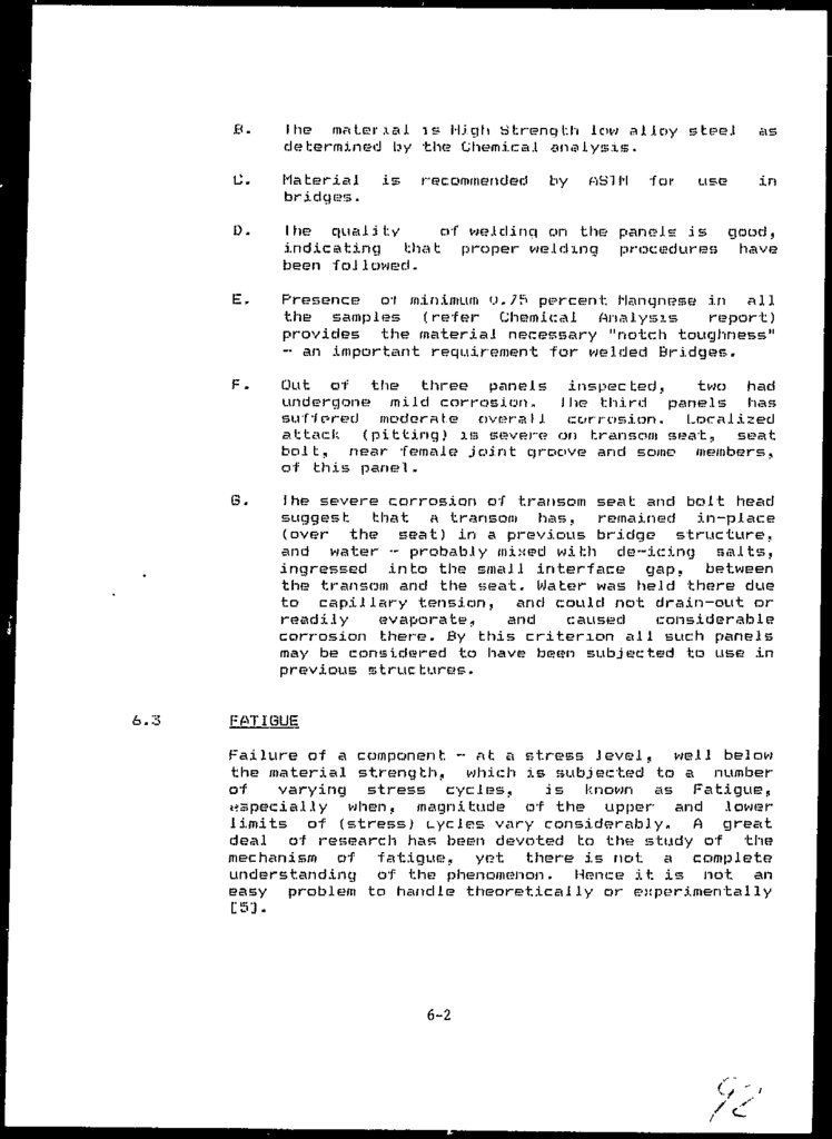
6.1
6.2
6.2.1
6.3
6.4
6.5
6.6
6.7
6.8
SITE VISI1 REPORT
CORROSION AND FATIGUE
Corrosion
Observations on Corrosion
Views of corrosion Expert
Fatigue
Mechanism of Fatigue
Corrosion and Fatigue combined
Protective film/coating
Strength of the structural members
Stress Redistributions
6.
CHAPTER-77.1
7.2
7.3
7.4
CONSULTANTS REPORT
Findings of the Meetings
Summary of the studies ancl Lest;
Conclusion
Discussion
APPENDICES
APPENDIX - J
List cd References
APPENDIX - II
Computer Analyses Results
APPENDIX •- I l l
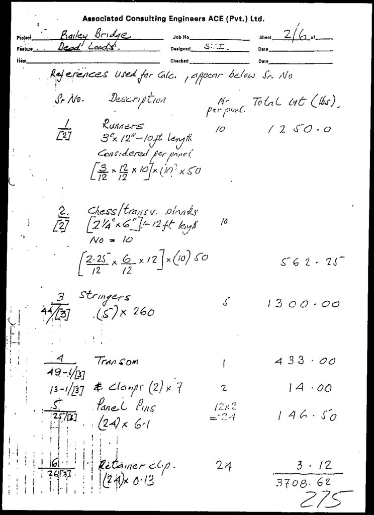
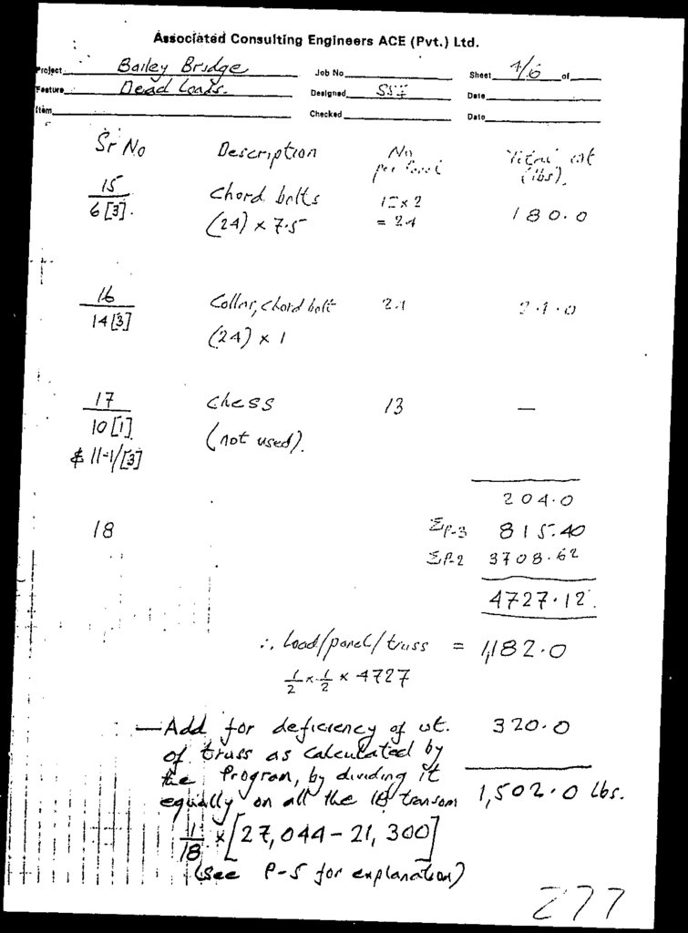
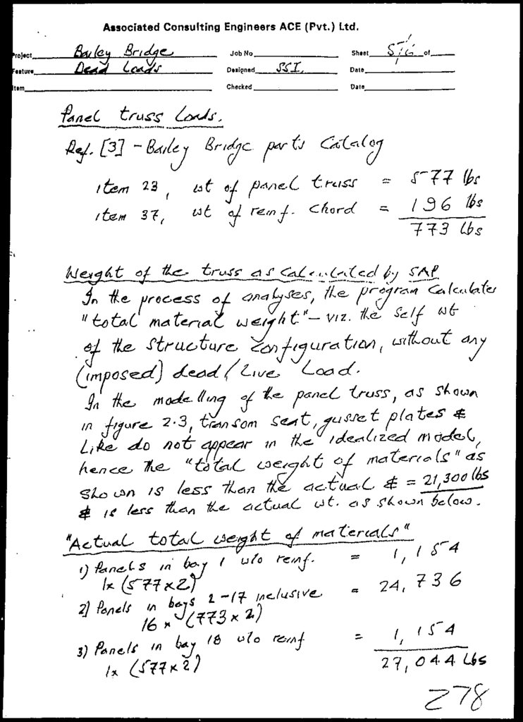
Panel Load
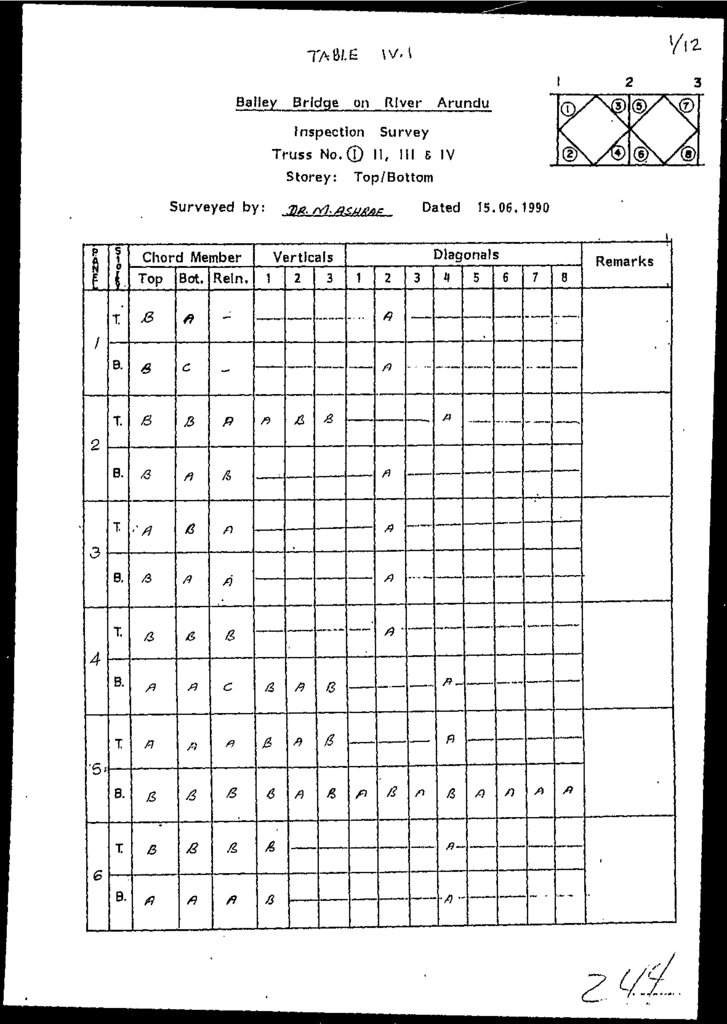
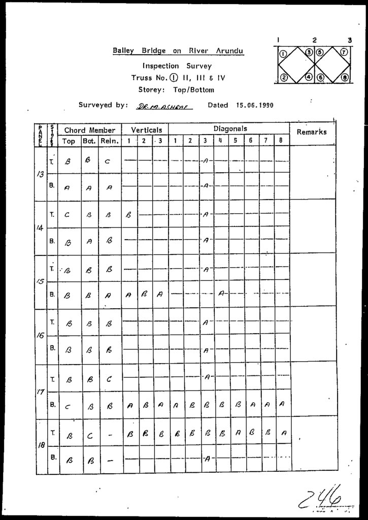
APPENDIX •- IV
Data c o l l e c t e d At Bite
APPENDIX •- V
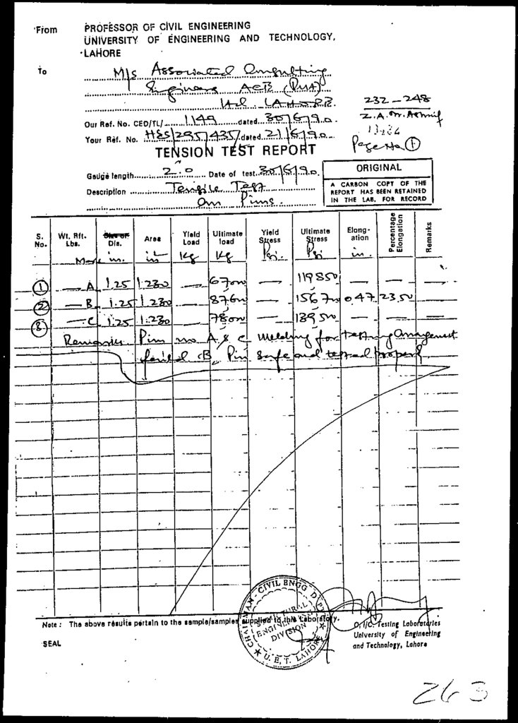
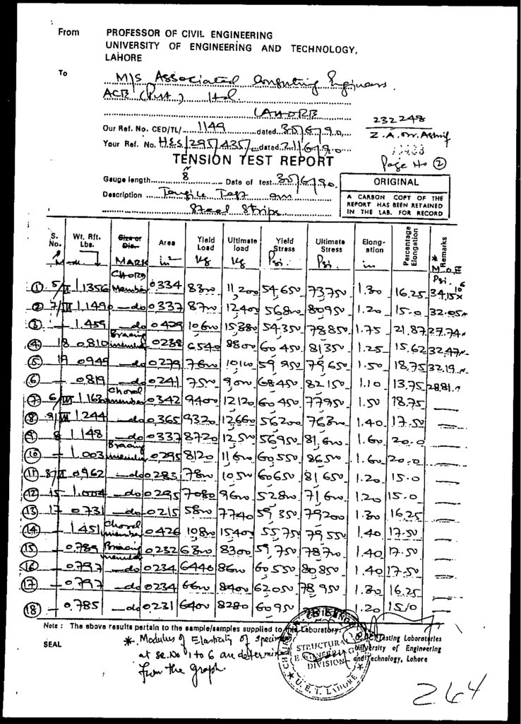
IJlienucaJ And lension
APPENDIX •- VI
Observations ort Corrosion And Fatigue
APPENDIX -- VII
Support.ing Figures
APPENDIX - VIII
Maintenance Plan & Schedule
(iii)
testing Results
lest: Results
7.
PART - 1MAIN REPORT
8.
SUMMARY REPORT9.
ASSOCIATED CONSULTINGENGINEERS ACE (PVT)
LTD.
SWlliARY
1.0
REEQ&I
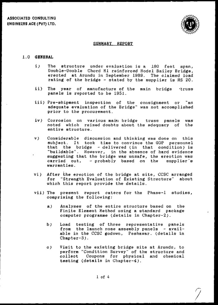
GENERAL
i;
The structure under evaluation is a 180 feet span,
Double-Oouble Chord HI reinforced Model Bailey Bridge,
erected at Arundu in September 1989. The claimed load
rating of the bridge - stated by the supplier is HS 20.
ii)
The year of manufacture of the
panels is reported to be 1951.
main
bridge
-truss
iii) Pre-shipment inspection of the consignment or "an
adequate evaluation of the Bridge" was not accomplished
prior to the procurement.
iv>
Corrosion on various maiii bridge
truss panels
noted which raised doubts about the adequacy of
entire structure.
v)
Considerable discussion and thinking was done on this
subject. It took time to convince the GOP personnel
that the bridge - delivered (in that condition) is
"buildable". However, in the absence of hard evidence
suggesting that the bridge was unsafe, the erection was
carried out,
- probably based on the
supplier's
warranties.
vi)
After the erection of the bridge at site, CCSC arranged
for "Strength Evaluation of Existing Structure" about
which this report provide the details.
vii) The present report caters for the
comprising the following:
Phase-1
studies,
a)
Analyses of the entire structure based on the
Finite Element Method using a standard package
computer programme (details in Chapter-2).
b)
Load testing of three representative panels
from the launch nose assembly panels - available in the CCSC godown, Peshawar, (details in
Chapter-3).
c)
Visit to the existing bridge site at Arundu, to
perform "Condition Survey" of the structure and
collect
Coupons for physical and chemical
testing (details in Chapter-4).
1 of 4
was
the
10.
ASSOCIATED CONSULTINGENGINEERS ACE (PVT) LTD.
Physical and chemical test on about 30 coupons
performed in laboratories at Lahore (details in
Chapter-5;.
e)
2.0
3.0
Evar.ation of the safe/permissible vehicle load
class on the bridge (details in Chapter 6&7).
STRUCTURE ANALYSES
i)
Analyses was carried out for entire structure based on
the Finite Element Method. Various vehicle load class
was studied (HS 20, H 15 etc.) to find the dead and
live load forces caused in different members.
ii;
Structure Analyses for AASHTO H 20 vehicle load class •the heaviest vehicle, has shown that the deflection of
the as-built structure, under the dead and live load
remains within permissible limits and that the dead
Jsad force in the chords are a major component of the
total (= 60.5 K).
PANEL LOAD TESTING
i)
Two panel load tests were conducted at the University
of Engineering and technology Laboratories Lahore as
under:
Test Ho.i: Single panel loaded at the top chord
as shown in Figure 3.8. The test was terminated
at 23,000 Kgf load due to excessive out of
plane movement of the panel frame at this load.
Test No.2: Two panels tested simultaneously in
compound form as shown in Figure 3.10. The
system stopped resisting further loading at
40,500 Kgf indicating failure. However, the
failure was initiated at a load of 19,500 Kgf.
ii) Absence of linear elastic behaviour in panel test No.2
since the early stages of loading, indicates that the
panels were subjected to the bottom chord loading previously.
2 of 4
11.
ASSOCIATED CONSULTINGENGINEERS ACE (PVT) LTD.
4.0
COHDITIOH SURVEY AND SITE VISIT
The Average Annual Daily Traffic (AADT) on the
is considered to be fairly lass.
Bridge
Condition Survey of the Existing Structure, carried out
by the Consultant's team, has indicated considerable
corrosion and evidence of fatigue/use of panel members
previously as explained hereunder. Other superstructure
components and masonry abutments are in good condition.
1
iv)
Cracks in the welding and/or repairs to the existing
welding was noted on some panels - especially at the
transom seat. This is considered to be an evidence of
fatigue or use of the members previously in a Bridge
structure.
Excessive pitting/severe corrosion on transom seat of
various panels as witnessed during examination of
Bridge at the site is considered to have been caused by
the ingress of water into the small interface gap
between the transom and the seat in an earlier bridge
structure, viz. evidence of previous use.
Protective paint and absence of corrosive environment
on the Existing structure shall however, limit the
corrosion fatigue effects on the Existing Structure.
5.0
CHEMICAL AMD PHYSICAL TESTING
i)
One panel was weighed at UET Laboratories Lahore. The
weight of the panel was about 261.0 Kg = 575 Ibs. Mo
deduction is made for any coating/film of enamal paint
applied recently. This is considered to be in agreement
with [1].
.ii)
Chemical and physical testing of the coupon material carried out in Laboratories at Lahore comprised the
following:
Chemical testing;
Tension testing;
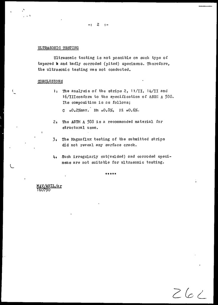
Magnaflux testing;
Macroscopic examination;
Shaping operation;
Boring operation; and
Ultrasonic testing
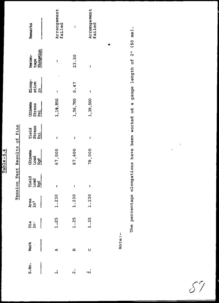
besides, tension test was conducted on 3 pins.
3 of A
12.
ASSOCIATED CONSULTINGENGINEERS ACE (PVT) LTD.
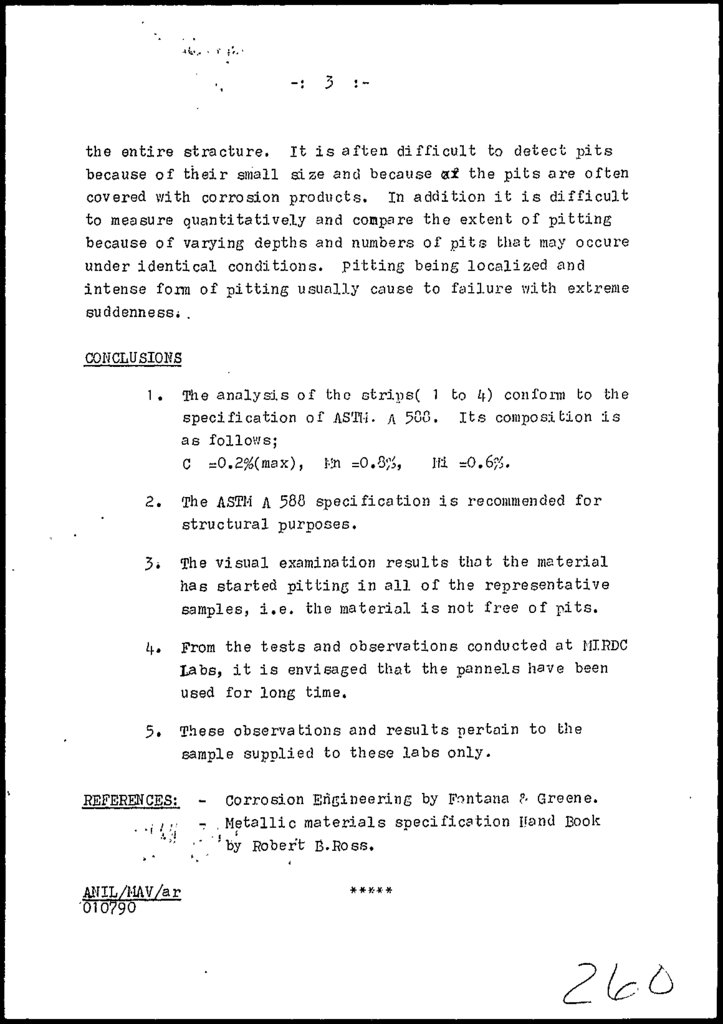
iii) Chemical and physical testing of the material coupons
has indicated that the material complies with AST11 A
572 and A 588. However, as neither of these standards
was in force in 1951 - the year of manufacture of the
panels, the material may be said to be near to these
standards. Overall, the material is high strength, low
alloy steel having necessary notch toughness and recommended for use in Bridge Structures.
iv)
6.0
7.0
Three panels transported to Lahore were got examined by
a Corrosion Expert has confirmed the findings listed in
para 5--iii above. However, severe corrosion of transom
seat and bolt head is considered to have been caused
due to the ingress of water as explained above.
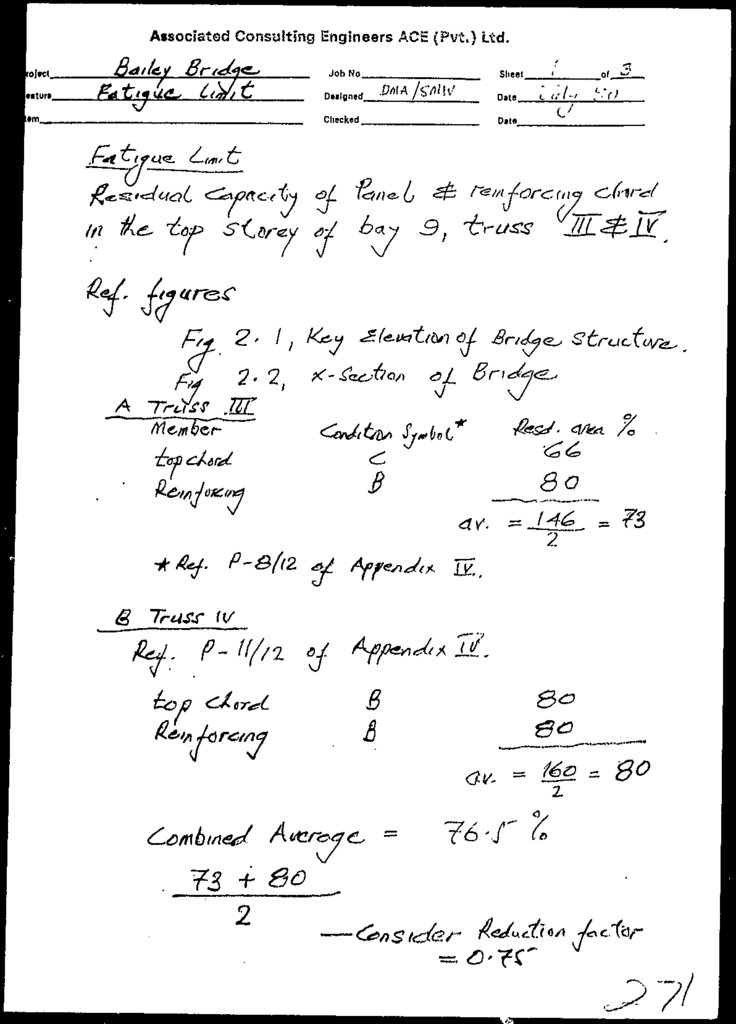
FATIGUE STRENGTH OF THE MEMBERS
i)
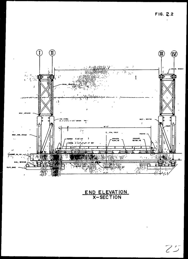
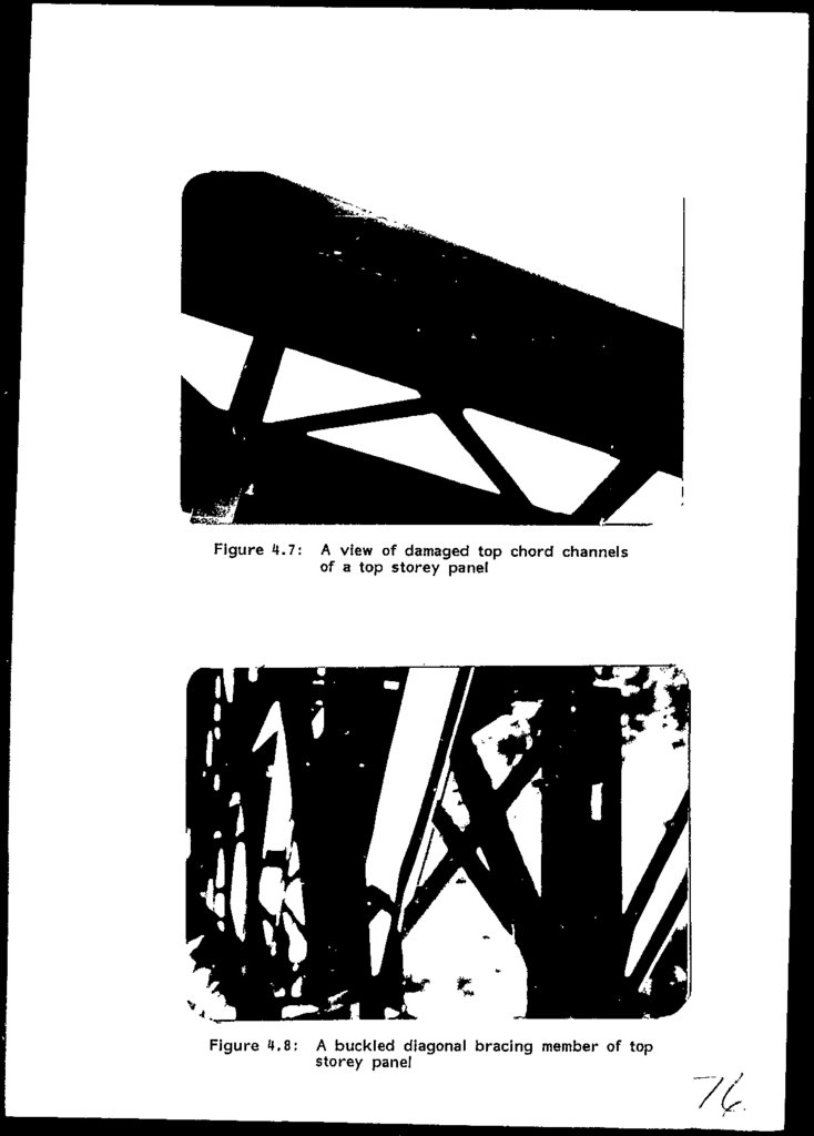
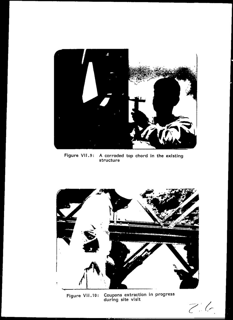
The condition of panel No.9 and 18 in the top storey of
truss No.Ill (ref. Figure 2.2) is considered to be the
worst. The "fatigue strength" of members is based on
the condition of these panels.
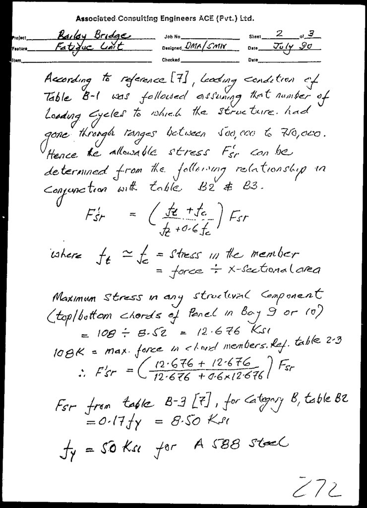
ii)
On the basis of physical and chemical testing and other
test results the fatigue limit of the member is calculated on the assumption of 500,000 to 750,000 stress
cycles completed by the structure members.
FINDINGS
i;
ii)
Based on the findings/results of the above tests and
studies,
the
Existing Structure configuration is
considered incapable of withstanding AASHTO HS 20
Loading. The analyses suggests that the bridge can be
subjected to a maxim.um w.heel load .class equivalent to
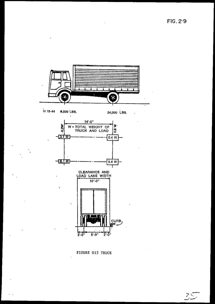
' H 15 Truck loading as shown in Figure 2.9 or H 18 with
caution, viz. maintaining near zero speed.
Even with the panels available in the present number
(including those used in the launch nose assembly) and
condition, the Bridge strength could be improved by
better planning/management viz. best chosen panels
w.r.t.
chord
condition,
used in bay 5 to
12
(inclusive).
4 of 4
13.
CHAPTER - 1INTRODUCTION
14.
UHAFTER i- j.INTRODUCTION
1.1
BftCKB.RO.UND
A
steel
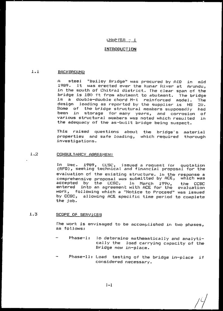
"Bailey Bridge" was procured by AID in mid
1989.
It was erected over the Kunar River at Arundu,
in the south of Chitral district. The clear span of the
bridge is 180 ft from abutment to abutment., The bridge
is a double-double chord 11-J. reinforced
model. The
design .loading as reported by the supplier is US 20.
Some of the bridge structural members supposedJy had
been in storage for many ye^rs,, and corrosion of
various structural members was noted which resulted in
the adequacy of the as-built bridge being suspect.
This raised questions about the bridge's
properties and safe loading, which required
investigations.
1.2
material
thorough
CONSULTANCY ABREEMENI
In Dec. 1989, CCSC, .Issued a request Cor quotation
(RFQ), seeking technical and financial proposal for the
evaluation of the existing structure. In the response a
comprehensive proposal was submitted by ACE, which was
accepted by the CCSC.
In March I99O,
the CCSC
entered
into an agreement with ACE for the evaluation
work, following which a "Notice to Proceed1 was issued
by CCSC, allowing ACE specific time period to complete
the job.
1.3
SCOPE OF SERVICES
The work is envisaged to be accomplished in two phases,
as follows:
Phase-1:
ID determine mathematically arid analytically the load carrying capacity of the
Bridge now in-place.
Phase-11: Load testing of the bridge in-plac:e
considered necessary.
1-1
if
15.
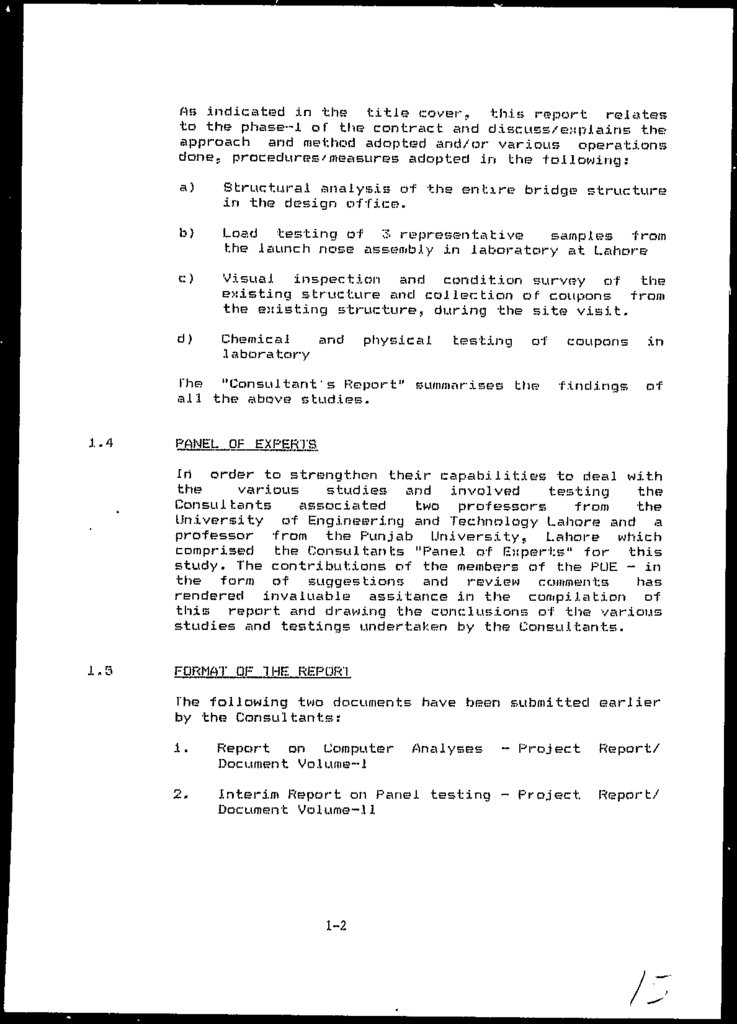
As indicated in the title? cover,, this report relatesto the phase™! of the contract and discuss/explains the
approach and method adopted and/or various operations
done, procedures/measures adopted in the following:
a)
Structural analysis of the entxre bridge structure
in the design office.
b)
Load testing of 3 representative
samples from
the launch nose assembly in laboratory at Lahore
c:)
Visual inspection and condition survey of the
existing structure and collection of coupons from
the existing structure, during the site visit.
d)
Chemical
and
.laboratory
physical
testing
of
The "Consultant's Report" summarises the
all the above studies.
1.4
coupons
in
findings
of
PANEL OF EXPERTS
in order to strengthen their capabilities to deal with
the
various
studies and involved
testing
the
Consultants
associated
two professors
from
the
University of Engineering and Technology Lahore and a
professor from the F'unjab University, Lahore which
comprised the Consultants "Panel of Experts" for this
study. The contributions of the members of the PUE - in
the form of suggestions and review comments
has
rendered invaluable assitance in the compilation of
this report and drawing the conclusions of the various
studies and testings undertaken by the Consultants.
1.5
FORMAT OF THE REPOR'l
The following two documents have been submitted earlier
by the Consultants:
1.
Report on Computer
Document Volume-1
- Project
Report/
2.
Interim Report on Panel testing - Project
Document Volume-!1
Report/
1-2
Analyses
16.
The report is written in a form and sty is so as to beself consistent,
viz. reference to other project
report/documents submitted earlier and superceded by
this document is not required.
1.6
REFERENCES
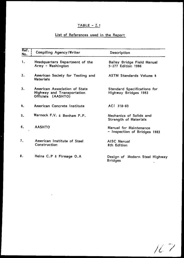
In
Appendix-!
various Standards/Books and
other
documents have been listed which were referred by the
Consultants. Reference to any document, in this report
is mentioned in a box f. ] bracket, with only the Sr. No.
mentioned there against that document/reference.
1-3
17.
CHAPTER - 2COMPUTER ANALYSIS
18.
CHAPTER - 2COMPUTER
2.1
ANALYSES
PREAMBLE
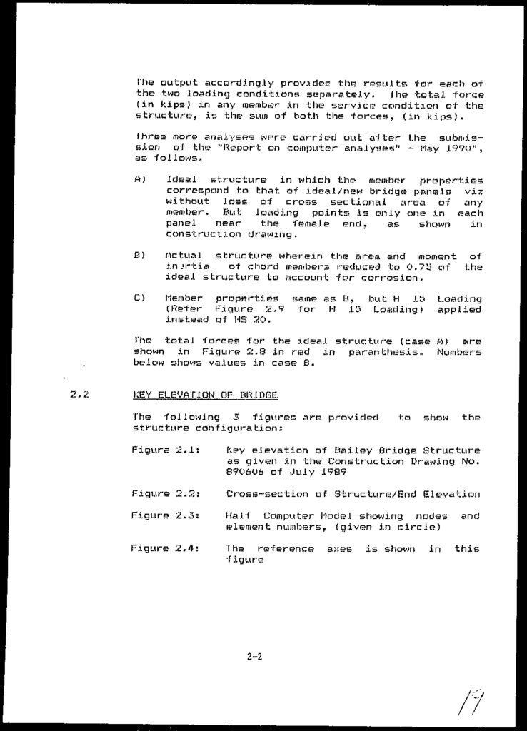
As envisaged in the lechnical Proposal, analyses of the
entire Bailey Bridge Stri.icLi.irB were carried out on
computer using a package program SAP - developed by the
University of California Berkeley. Details of the
analyses are given below.
2.1.1
Description of the Structure.
The structure comprises of IS double-double M-i Truss
Panels on each side,
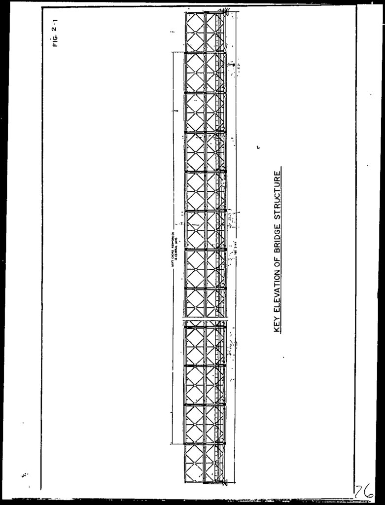
as shown in the Key Elevation
(Figure 2,1)
and Section (Figure 2.2). Panels
2-17
(inclusive) are reinforced at top and bottom chords by
an additional channel (Figure 2.1).
.2
Model 1 ing of the Sjruc ture
The structure is modeled as shown in figure 2.3. In the
true sense of the words, the program distinguishes a
'Frame Element' from 'Truss Element' only from the
fixity
conditions which is given to
be
those,
applicable for 'frame Elements' (except for the 'Pin
Joints' ) .
2.1.3
Input Parameters
The salient input parameters is given in Section
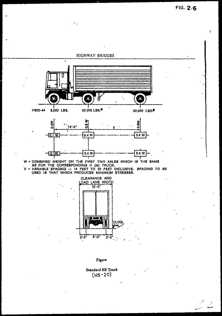
For HS 20 truck configuration refer Figure 2.6
2.1.4
2.3,
Output and Forces
In the input 2 loading conditions have been given:
Condition 1:
Condition 2:
Dead load of the structure
Live load from US 20 truck (except
Case C)
2-1
6
19.
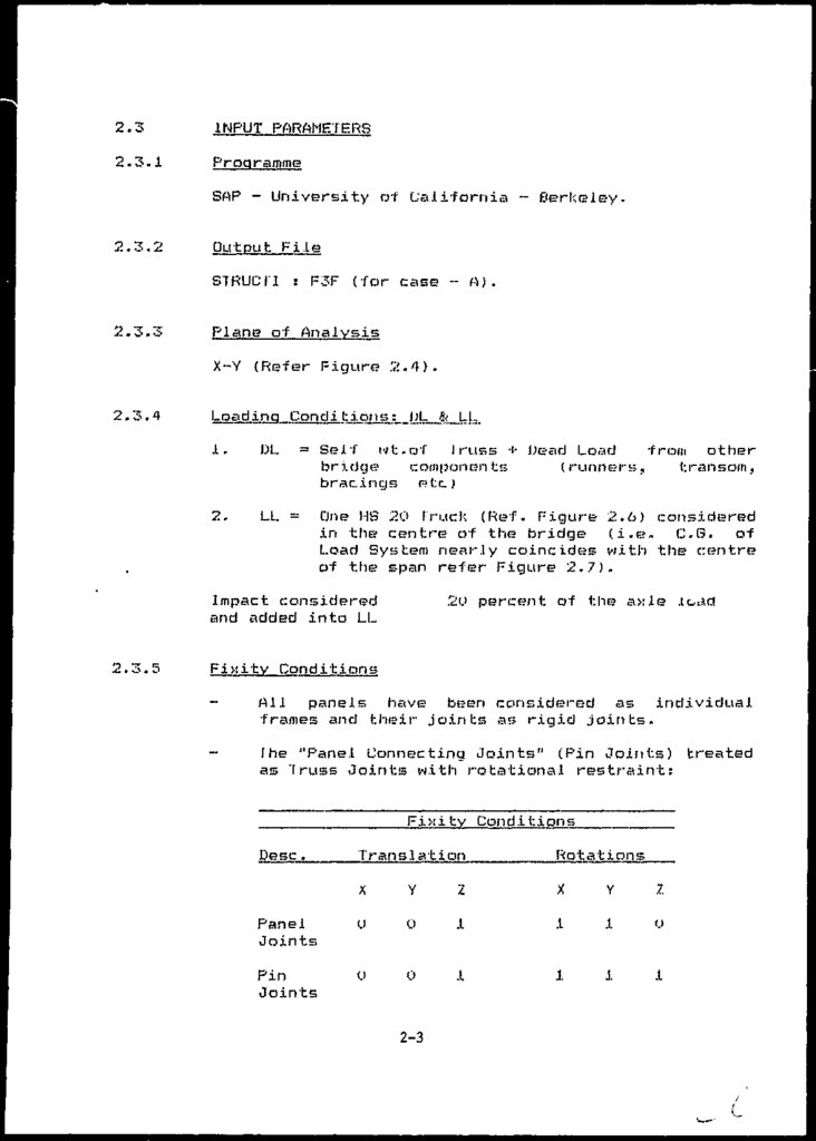
The output accord.ing.ly provides the results for each ofthe two loading conditions separately. fhe total force
(in kips) in any member in the service condition of the
structure, is the sum of both the forces, (in kips).
Ihree more analyses wpre carried out alter Lhe submission of the "Report on computer analyses" - Hay J.99O",
as follows.
A)
Ideal structure in which the member
properties
correspond to Lhat of ideal /new bridge panels vis:
without loss of cross sectional area of any
member. But loading points is only one in each
panel
near
the female end,
as
shown
in
construction drawing.
12)
Actual structure wherein the area and moment of
inertia
of chord members reduced to 0.715 of the
ideal structure to account for corrosion,
C)
Member properties same as E<, but: H .15
(Refer Figure 2.9 for H .15 Loading)
instead of HS 20.
Loading
applied
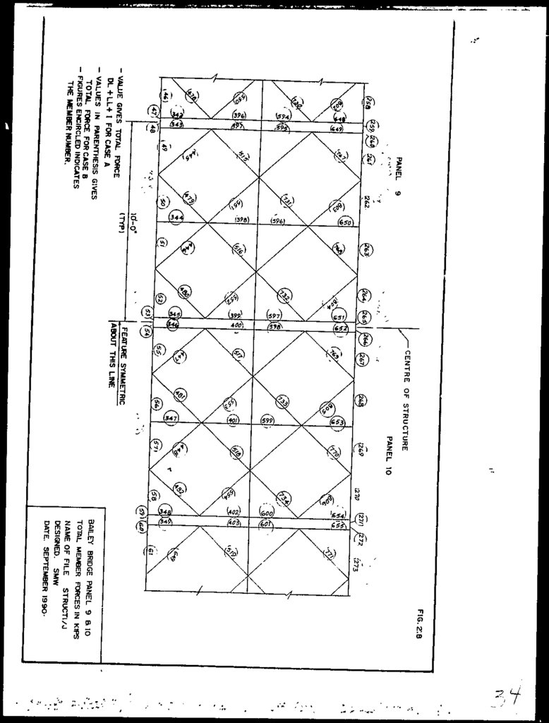
I'he total forcer, for the ideal structure (case H) are
shown in Figure 2.8 in red in paran thesis,. Numbers
below shows values in case B.
KEY ELEVATION OF BRIDGE.
The following 3 figures are provided
structure configuration:
to
show
the
Figure 2.it
Key elevation of Bailey Bridge Structure
as given in the Construction Drawing No.
890606 of July 1989
Figure 2.2:
Cross-section of Structure/End {Elevation
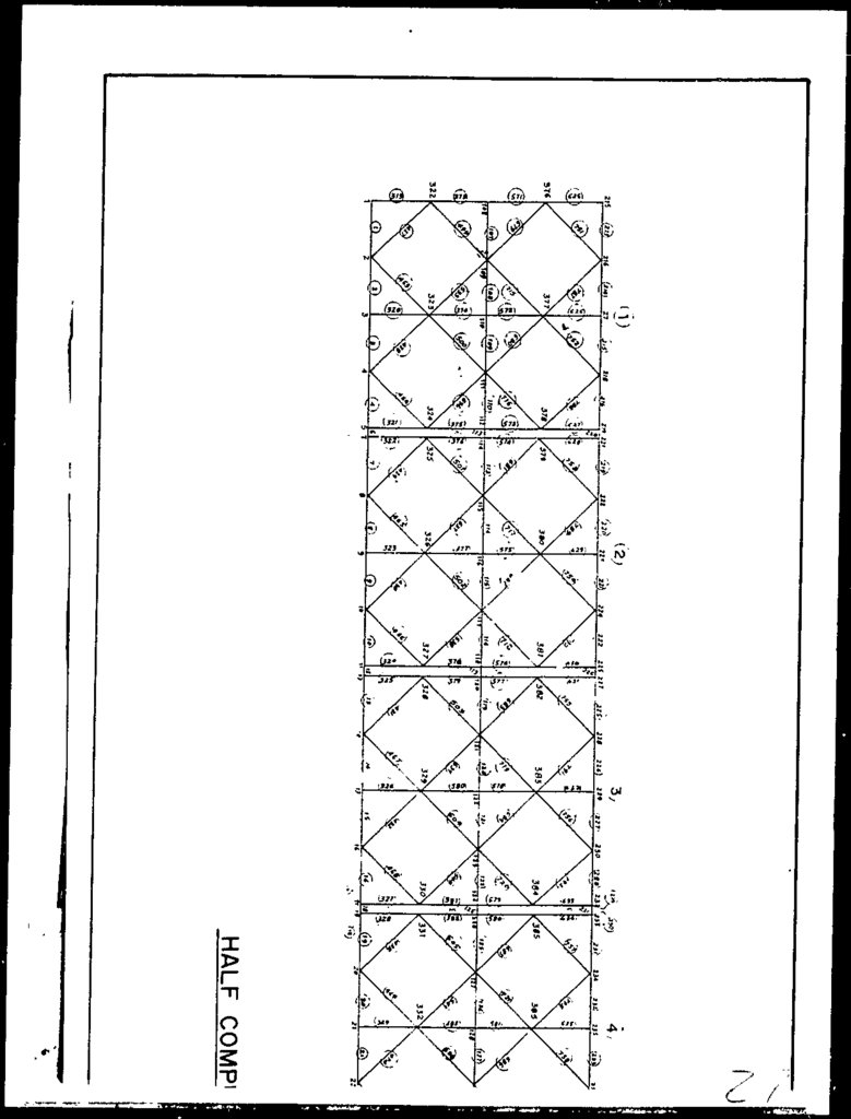
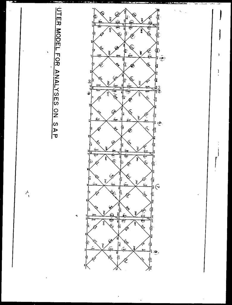
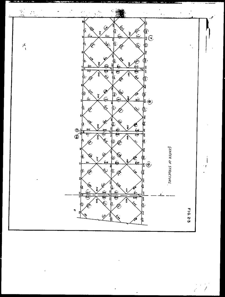
Figure
2.3:
Half Computer Hodel showing nodes
element numbers, (given in circle)
Figure
2.4:
I he reference
figure?
2-2
axes
is shown
in
and
this
20.
2.3INPUT PARAMETERS
2.3.1
Programme
SAP - University of California ~ Cerkeley,
2.3.2
Output File
STRUCT! : F3F (for case - A).
2.3.3
Plane of Analysis
X-Y (Refer Figure
2.3.4
2.4).
Loading Condi tio_ns; JjL& LL
1.
DL
= Self wt.of I russ + Dead Load
from other
bridge
components
(runners,
transom,
bracings r»tc.}
2.
LL -
One HS 20 I ruck (Ref. Figure 2.6) considered
in the centre of the bridge (i.e- C.G. of
Load System nearly coincides with the centre
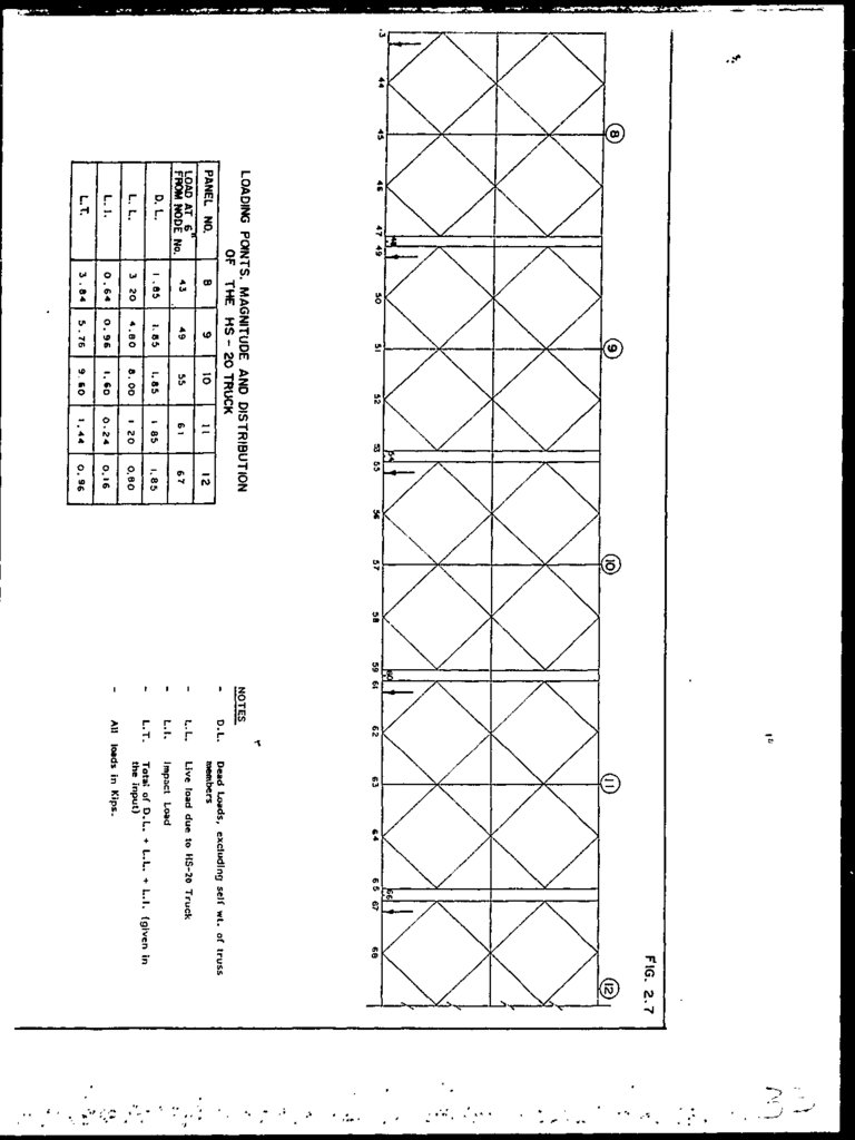
of the span refer Figure 2.7).
Impact considered
and added into LL
2.3.5
2U percent of the axle .load
Fixity Conditions
-
All panels have been considered as individual
frames and their joints as; rigid joints.
fhe "Panel Connecting Joints" (Pin Joints) treated
as Truss Joints with rotational restraint:
Fixity Conditions
Translation
Rotations
X
Y
2
X
Y
Z
Panel
Joints
o
0
J.
.1
JL
(.>
Pin
Joints
O
0
.1
1
1
.1
Desc .
2-3
21.
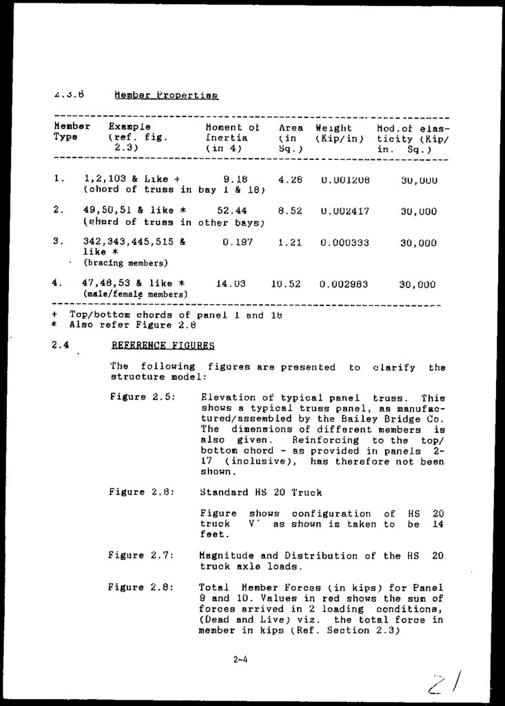
. J.6Member
Type
Member Properties
Example
(ref. fig.
2. -3)
Moment ot
Inertia
(in 4)
Area Weight
(.in
(Kip/in)
Sq. )
Mod. of: elasticity (Rip/
in. Sq.)
1.
1,2,103 & Like -f
9.18
(chord of truss in bay 1 & 18)
4.26
0.001208
30, 000
2.
49,50,51 & like *
52.44
of truss in other bays;
8.52
0.002417
30, 000
3.
342,343,445,515 &
like *
1 .21
0.000333
30,000
0.002983
30,000
0.197
(bracing members)
4.
+
*
2.4
47,48,53 & like *
(male/female members)
14.03
10.52
Top/bottom chords of panel 1 and Ib
Also refer Figure 2.8
REFERENCE FIGURES
The following figures are presented
structure model:
to
clarify
the
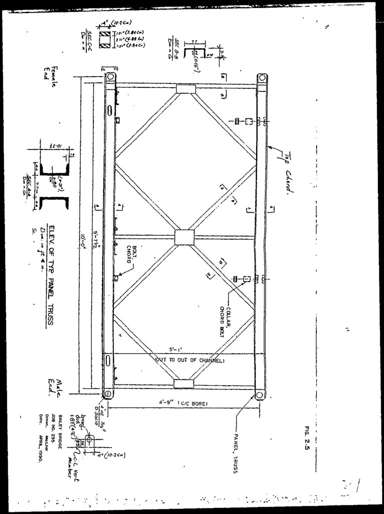
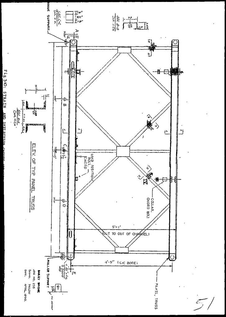
Figure 2.5:
Elevation of typical panel truss. This
shows a typical truss panel, as manufactured/assembled by the Bailey Bridge Co.
The dimensions of different members is
also given.
Reinforcing to the top/
bottom chord - as provided in panels 217 (inclusive), has therefore not been,
shown.
Figure 2.13:
Standard HS 20 Truck
Figure
truck
feet.
HS
be
20
14
Figure 2.7:
Magnitude and Distribution of the HS
truck axle loads.
20
Figure 2.8:
Total Member Forces (in kips) for Panel
9 and 10. Values in red shows the sum of
forces arrived in 2 loading conditions,
(Dead and Live) viz. the total force in
member in kips (Ref. Section 2.3)
2-4
shows configuration of
V' as shown is taken to
22.
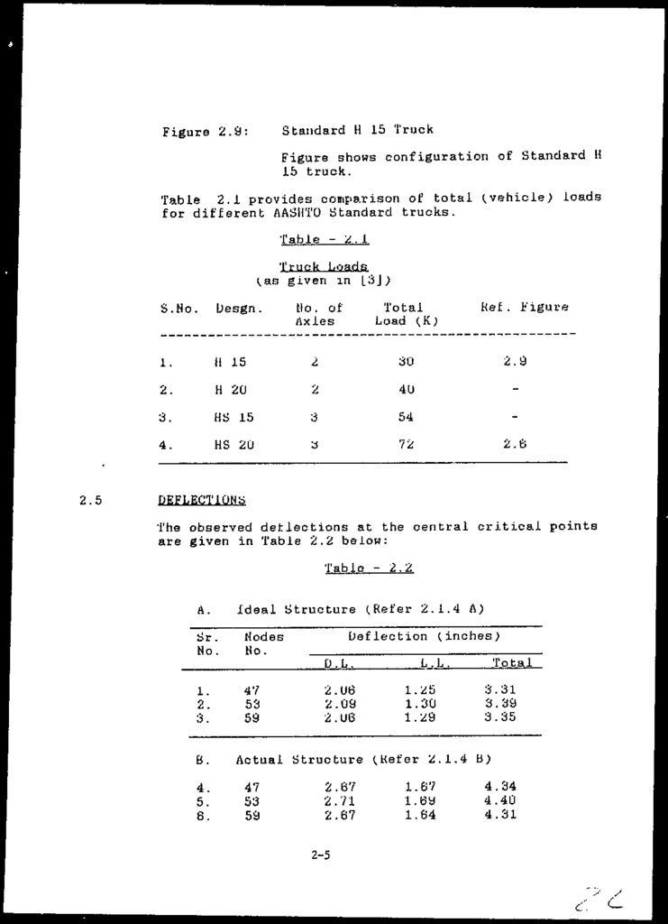
Figure 2.9:Standard H 15 Truck
Figure shows configuration of Standard H
15 truck.
Table 2.1 provides comparison of total (.vehicle; loads
for different AASIITO Standard trucks.
Table - 2 . 1
Truck Loads
(as given in |L3J;
2.5
Kef . Figure
Mo. of
Axles
Total
Load (K;
H 15
2
30
2.9
2.
H 20
2
40
-
3.
HS 15
3
54
-
4.
HS 20
a
72
2.6
S.No.
Desgn .
1.
DEFLECTIONS
The observed detlections at the central critical points
are given in Table 2.2 below:
Table - 2.2
A.
Sr.
No.
Ideal Structure (Refer 2.1.4 A)
Deflection (inches)
Modes
No.
D.L.
1.
2.
3.
B.
4.
5.
6.
47
53
59
2.06
2.09
2.06
L.L.
1.25
1.30
1.29
Total
3.31
3.39
3.35
Actual Structure (Kefer 2.1.4 B)
47
53
59
2.67
2.71
2.67
2-5
1.67
i.ey
1.64
4.34
4.40
4.31
23.
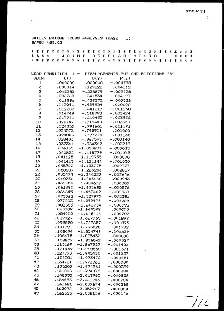
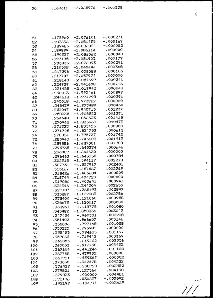
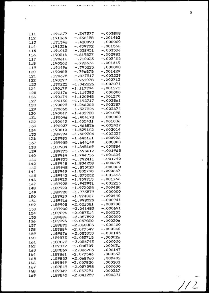
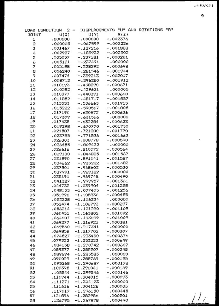
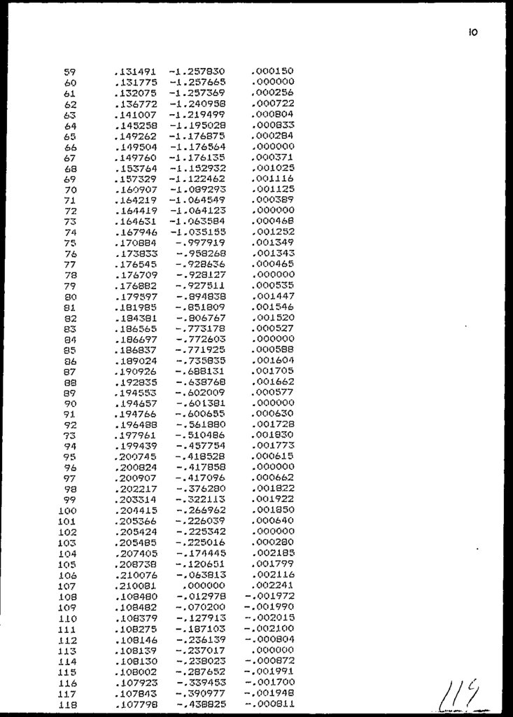
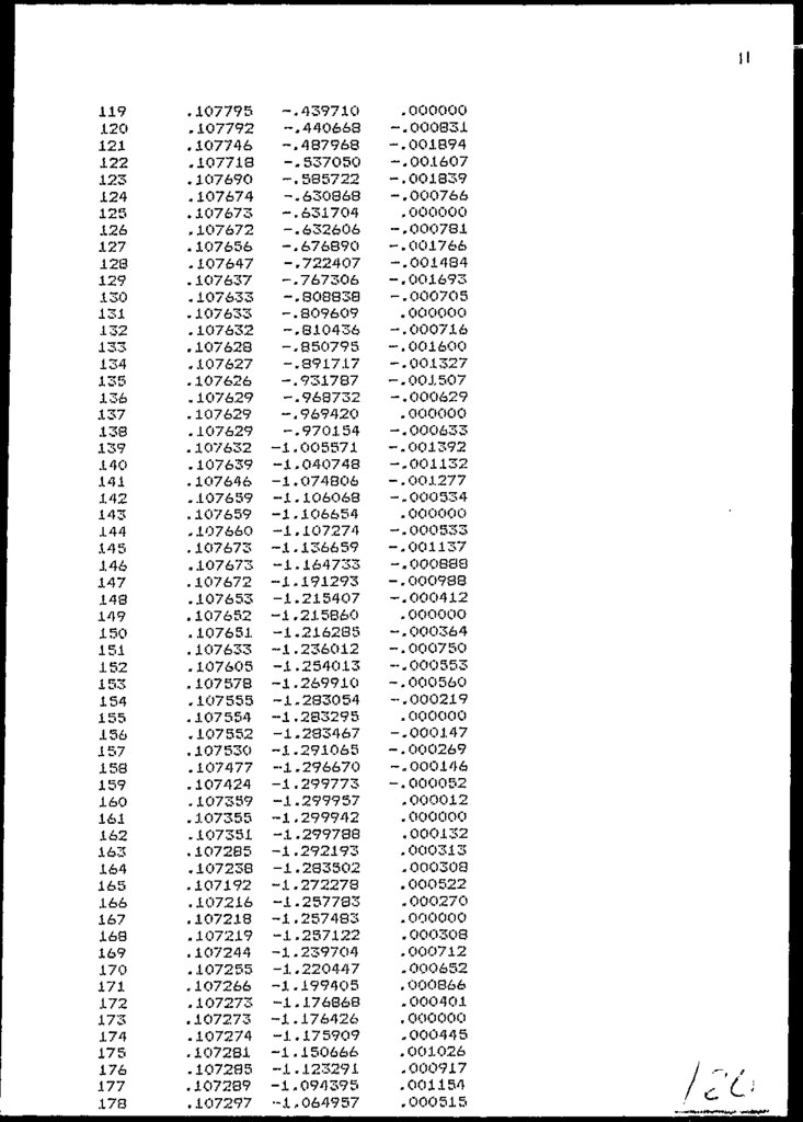
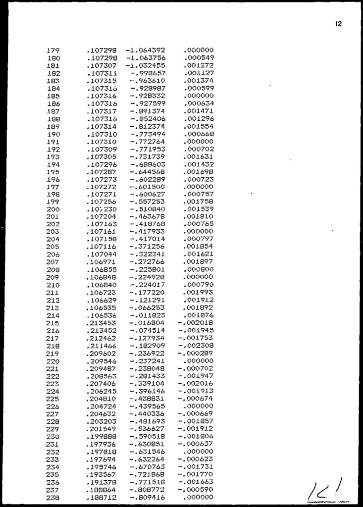
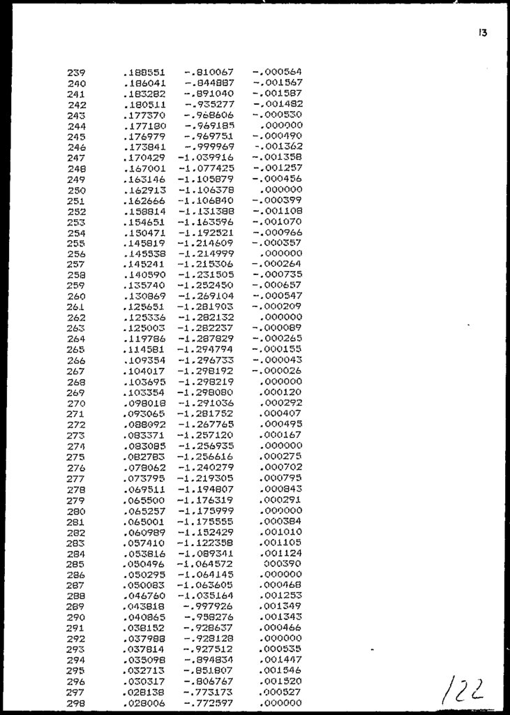
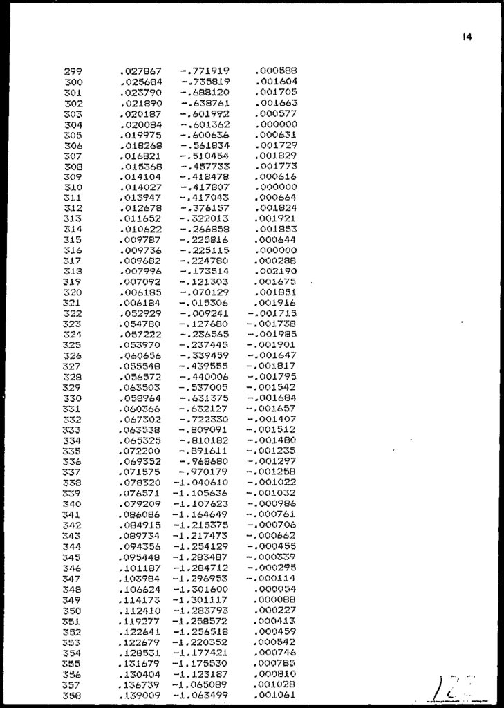
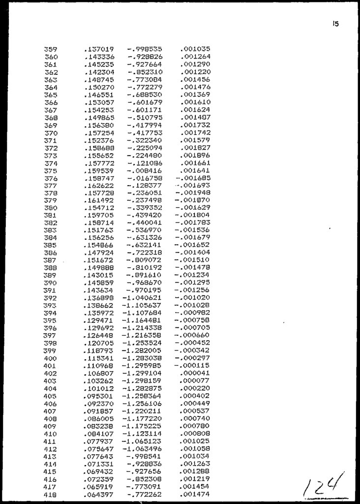
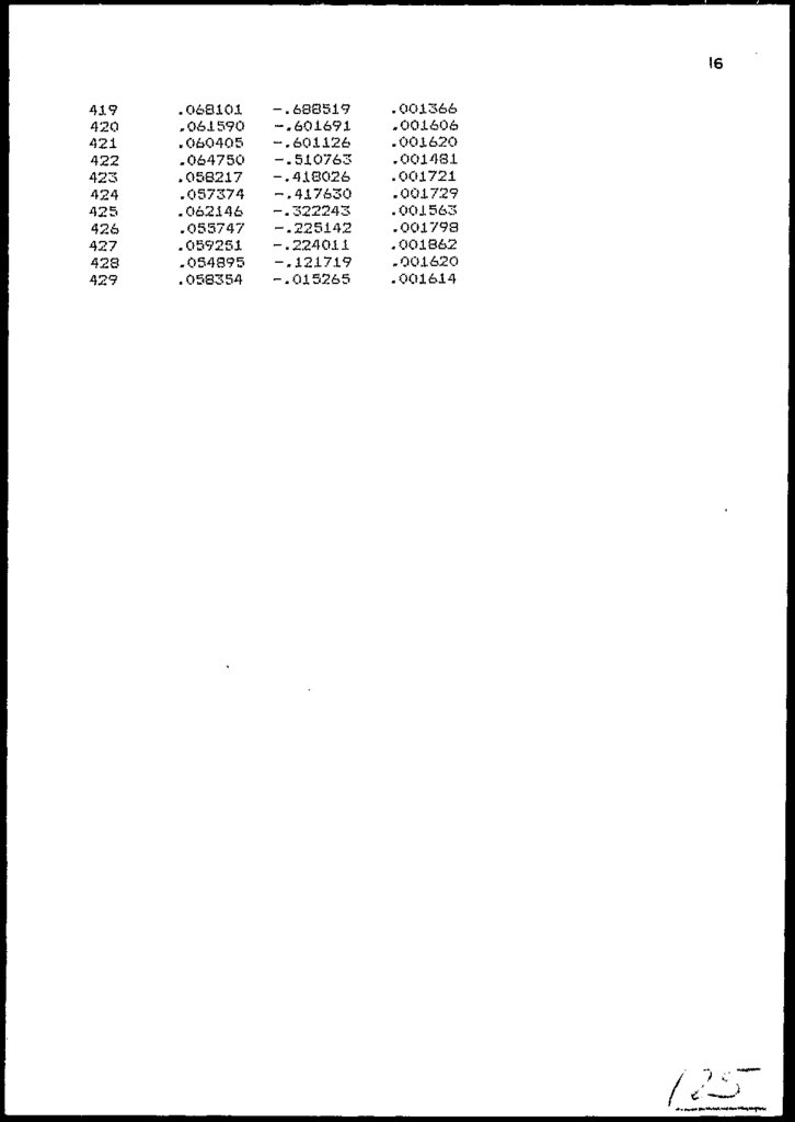
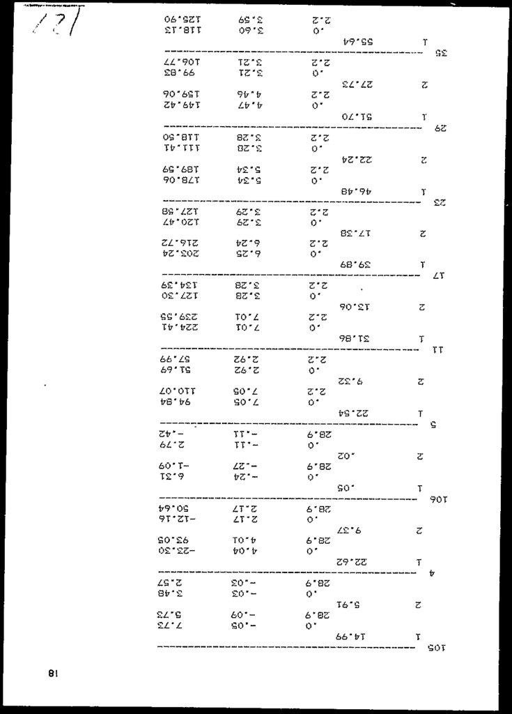
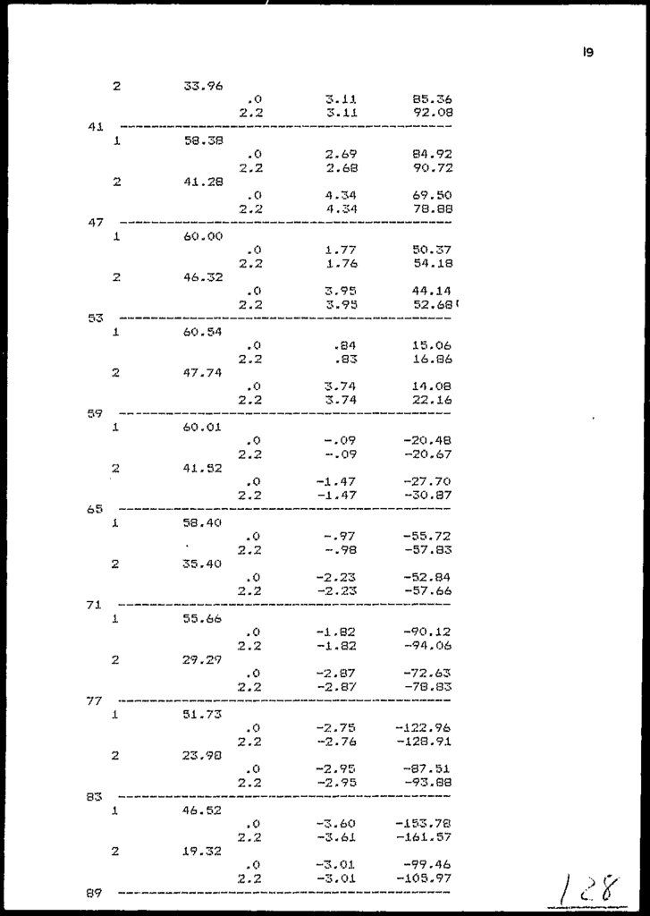
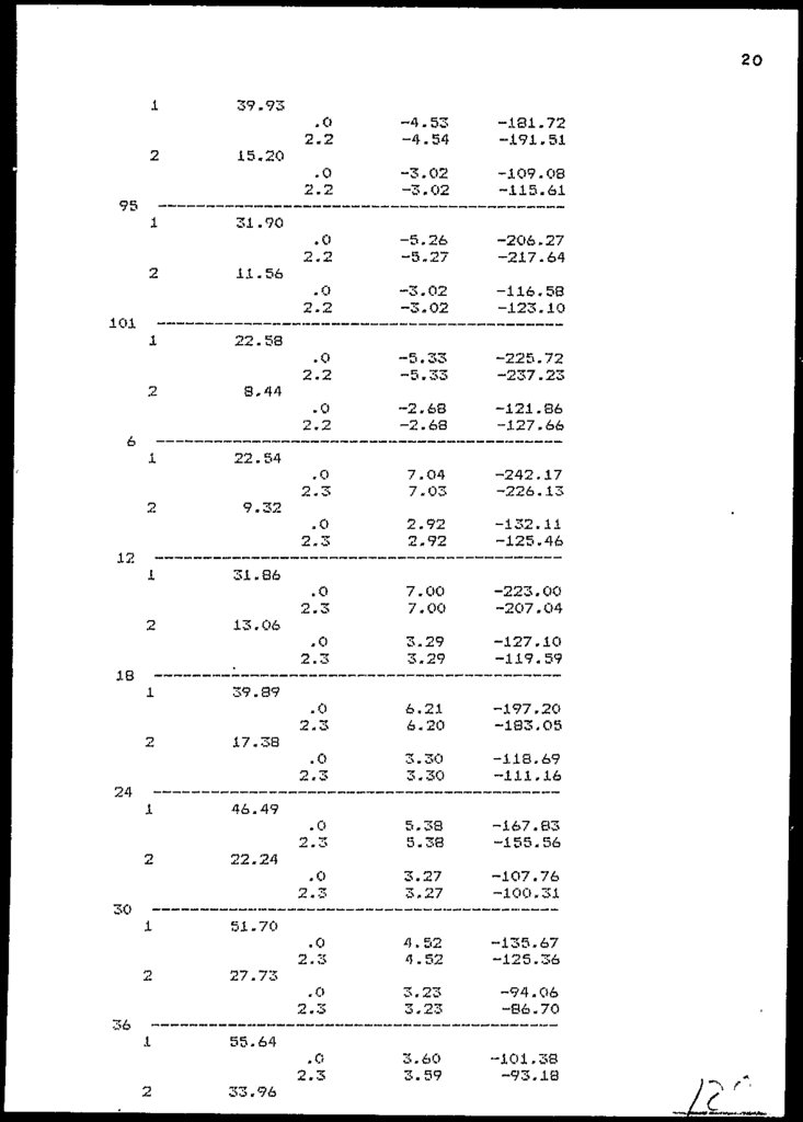
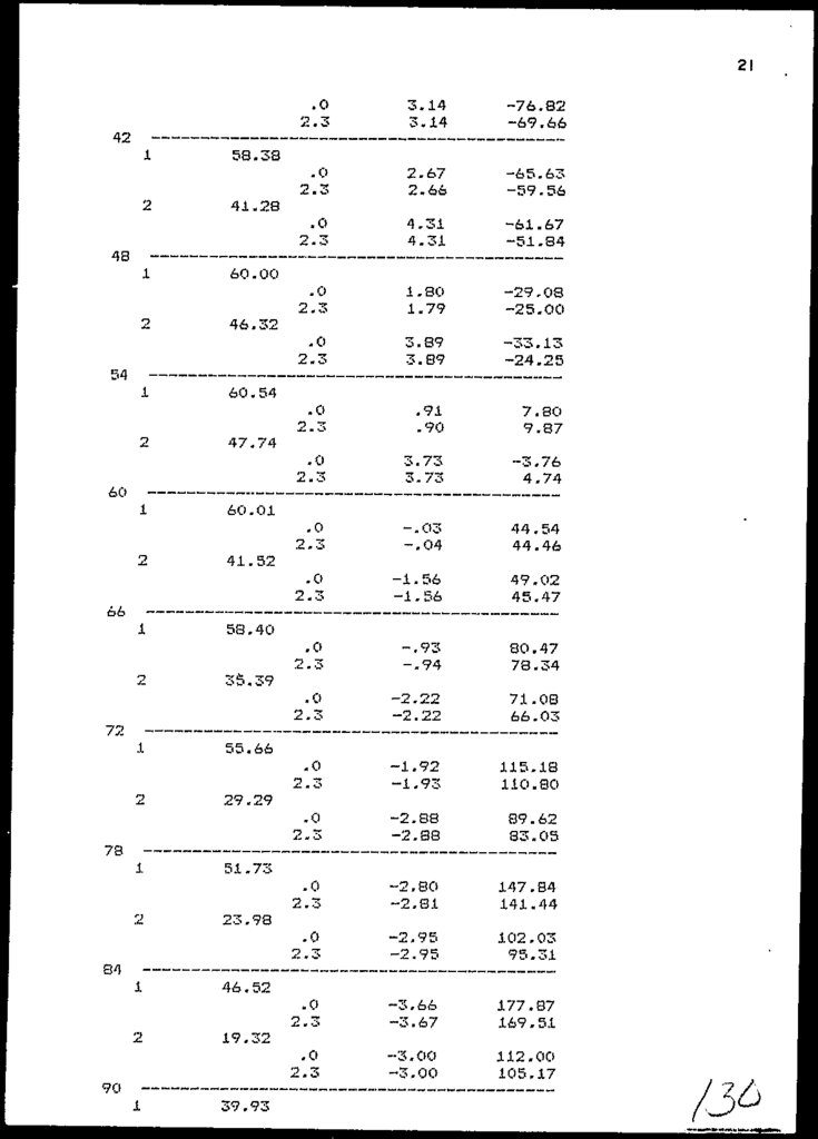
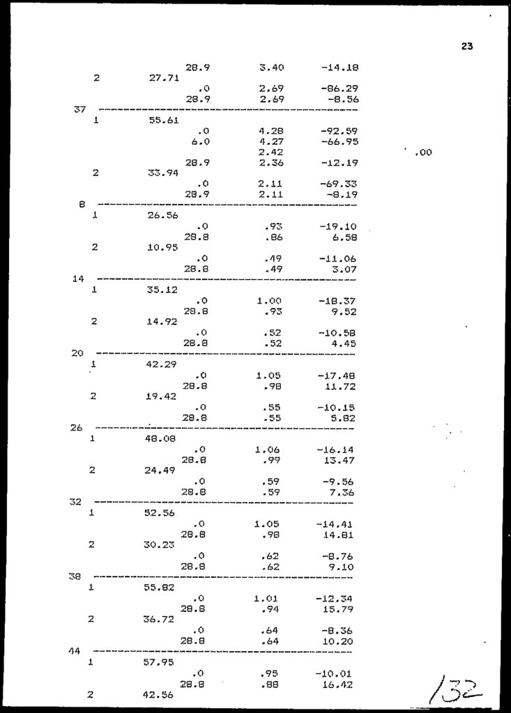
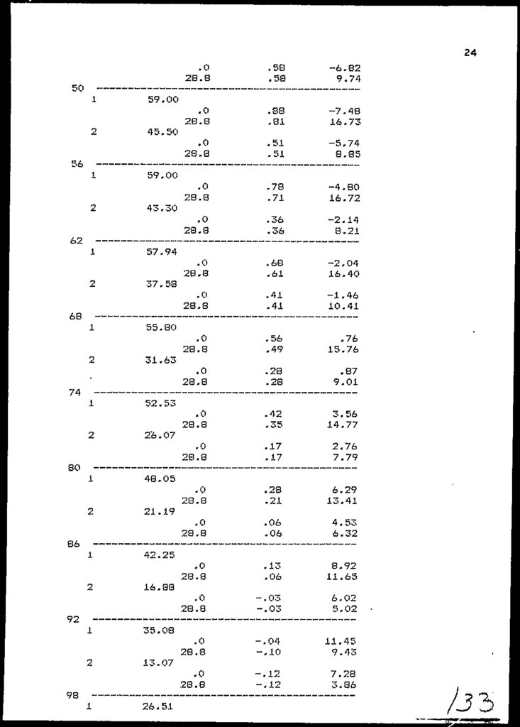
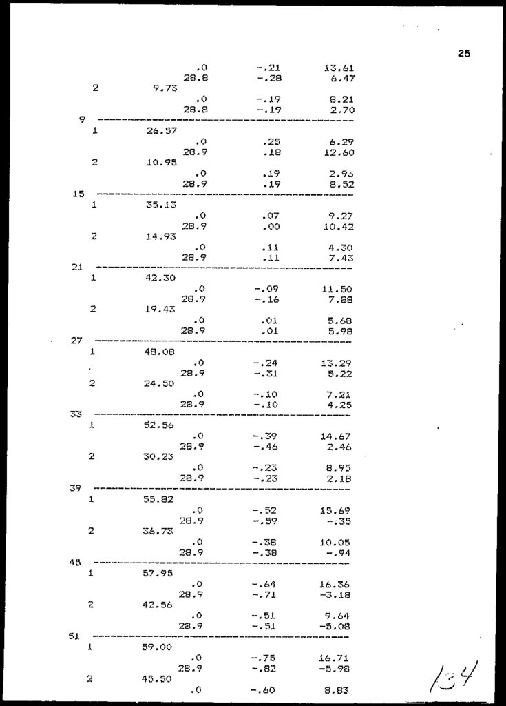
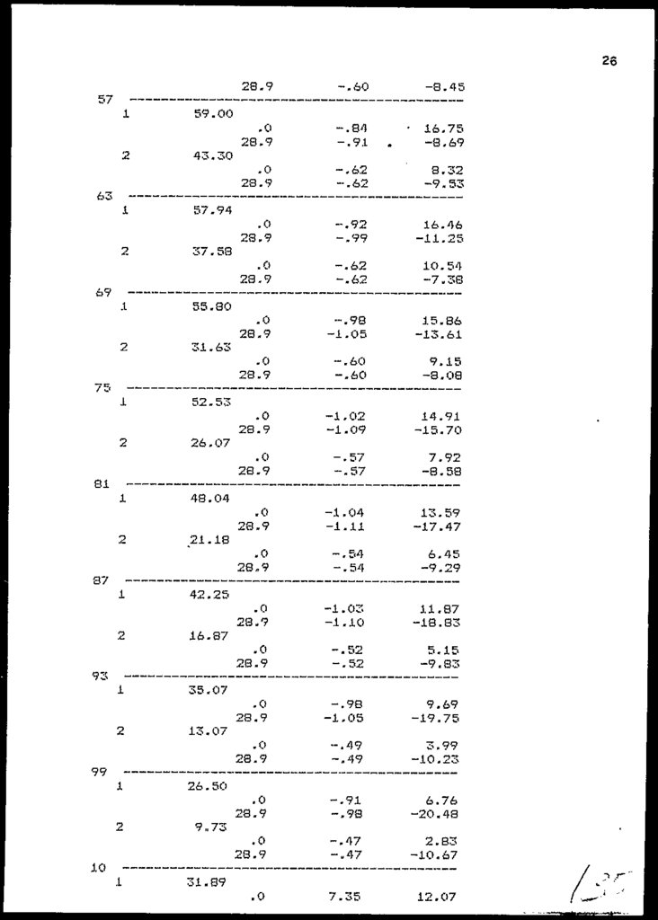
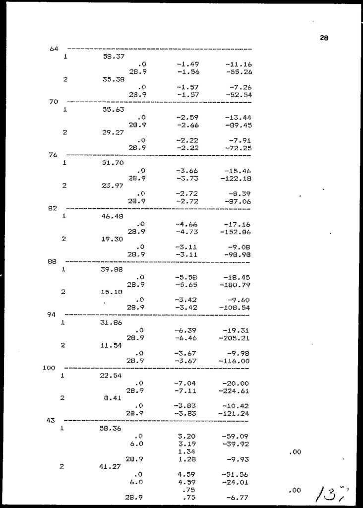
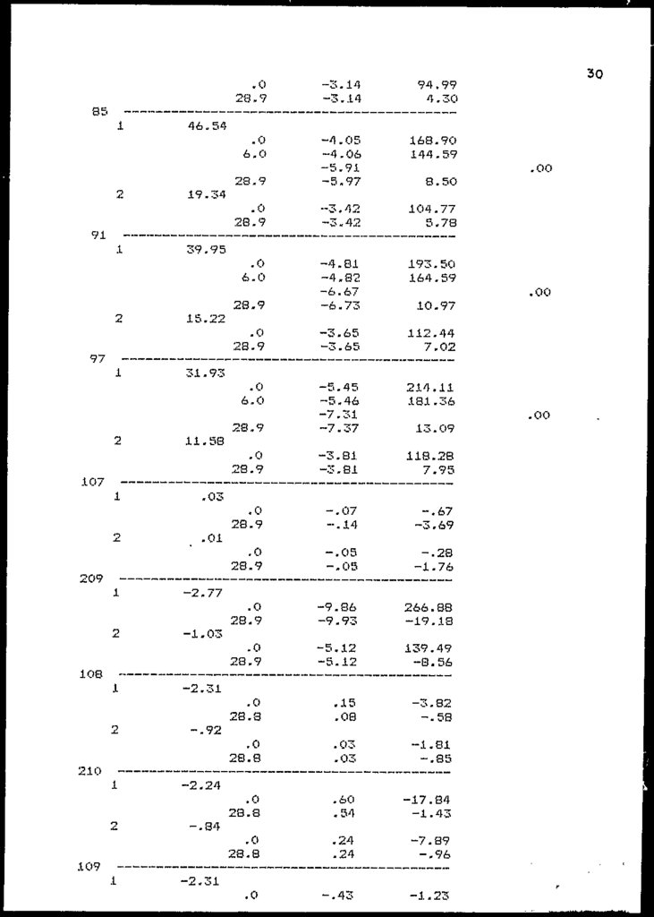
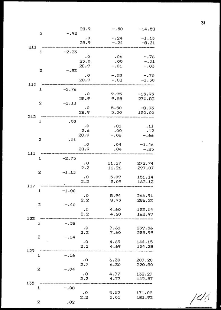
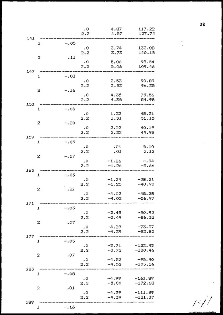
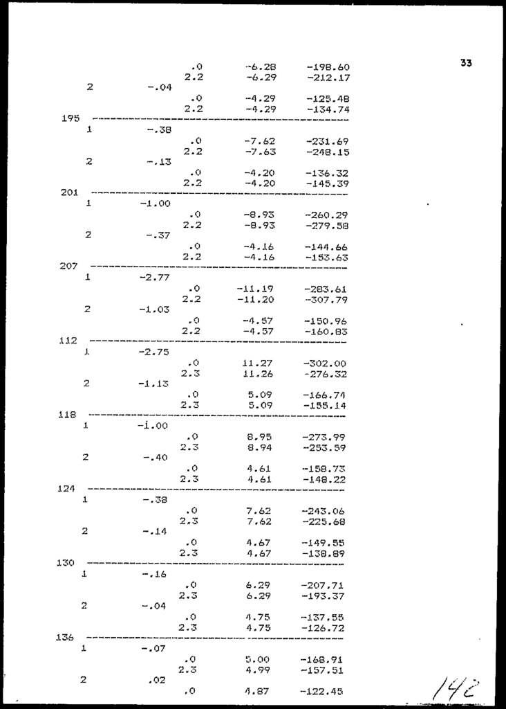
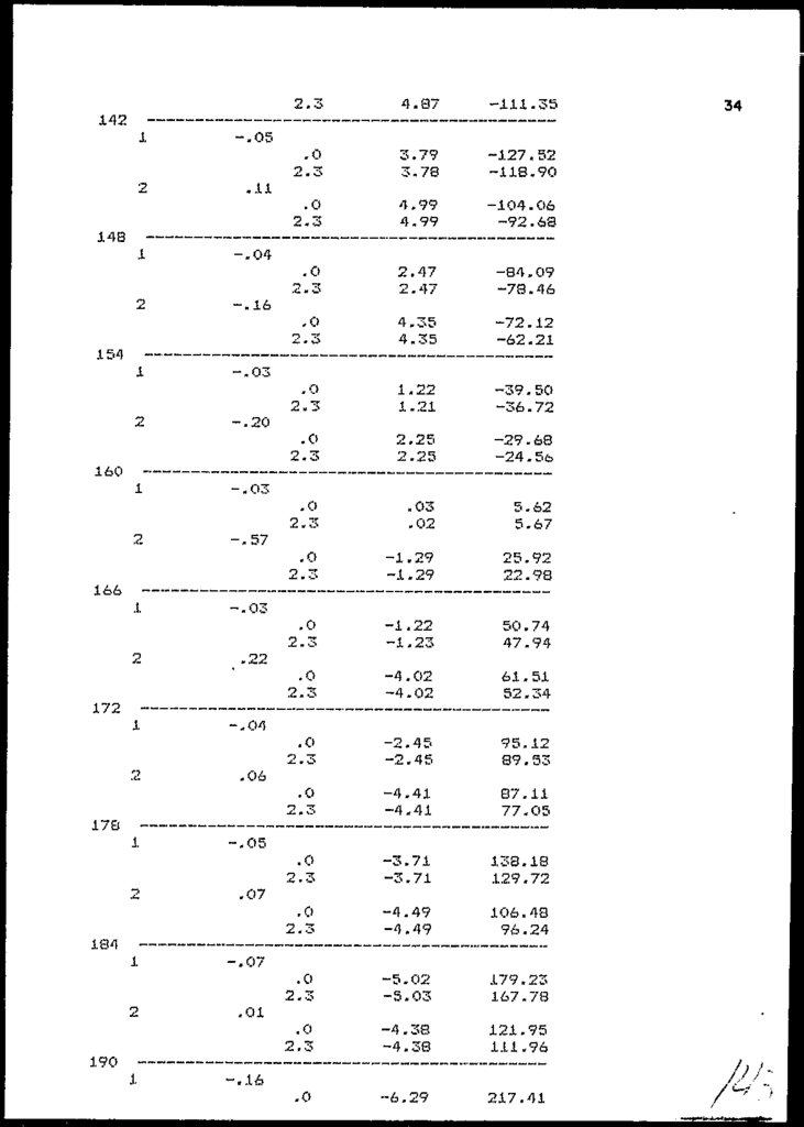
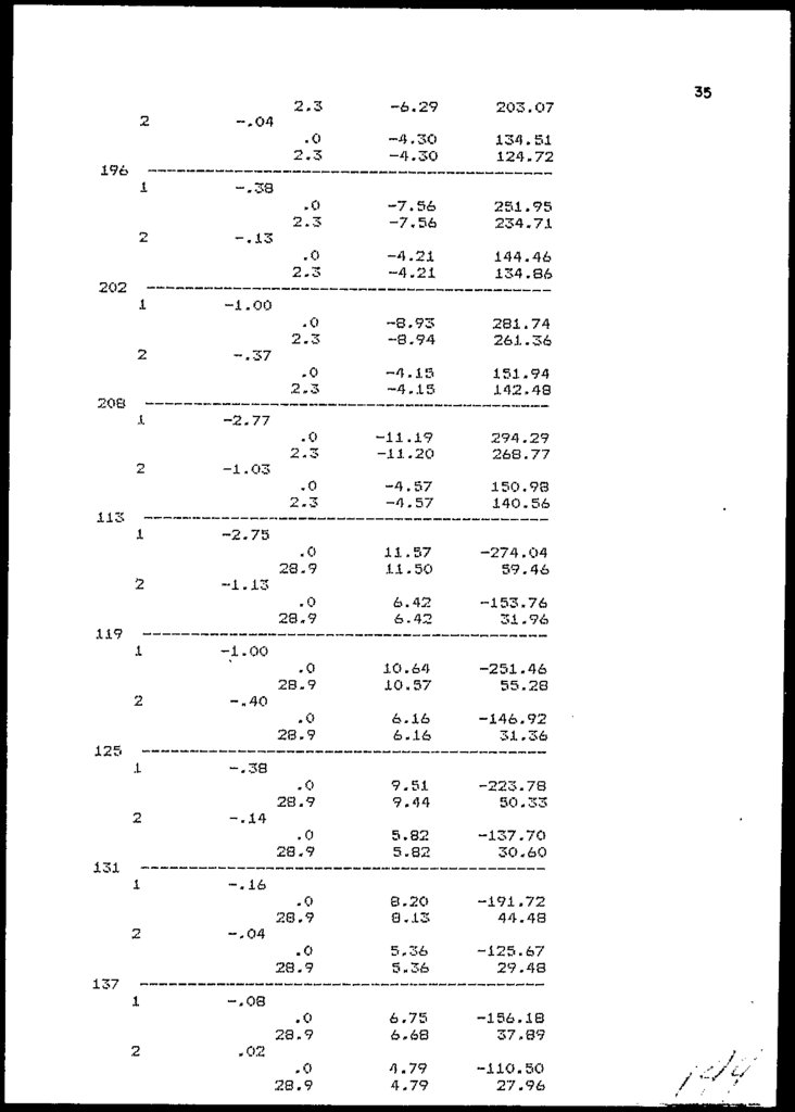
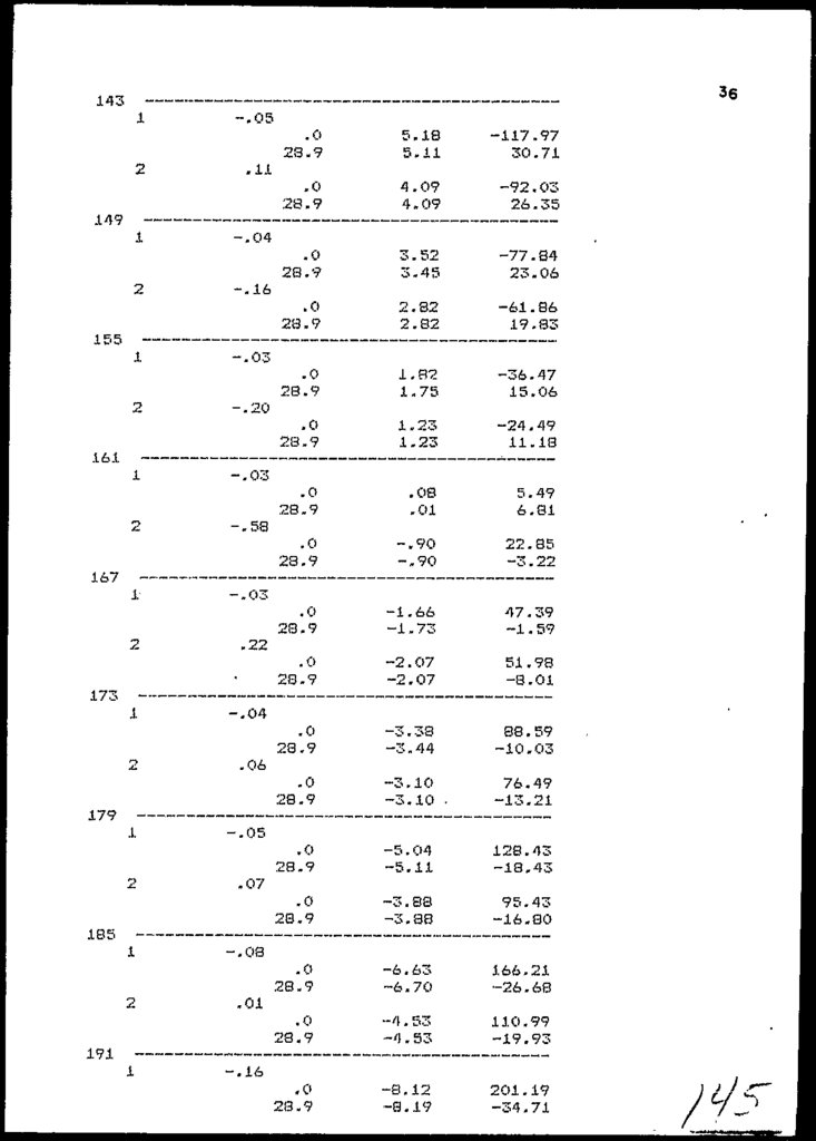
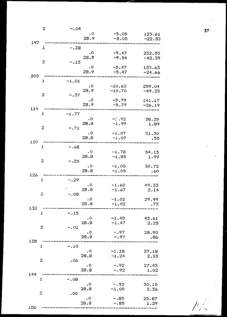
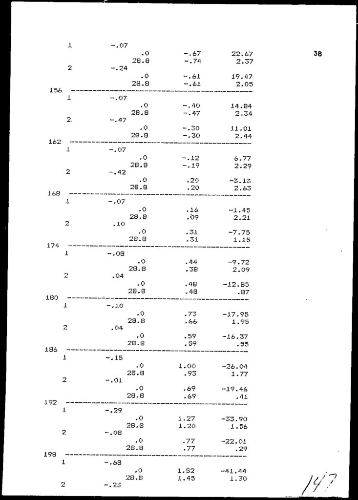
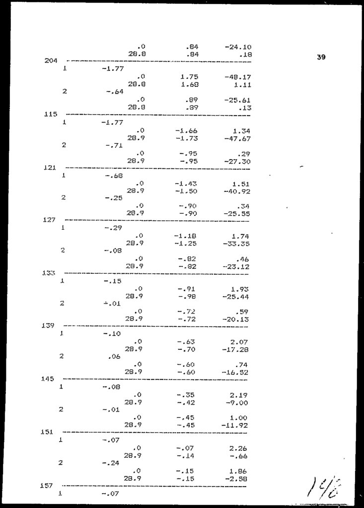
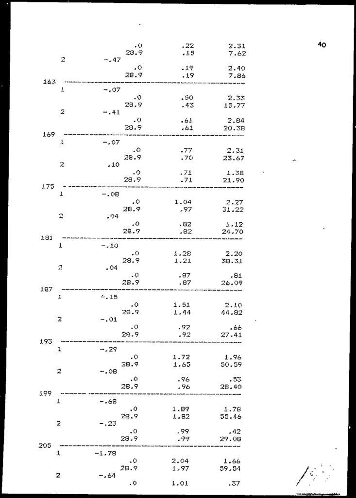
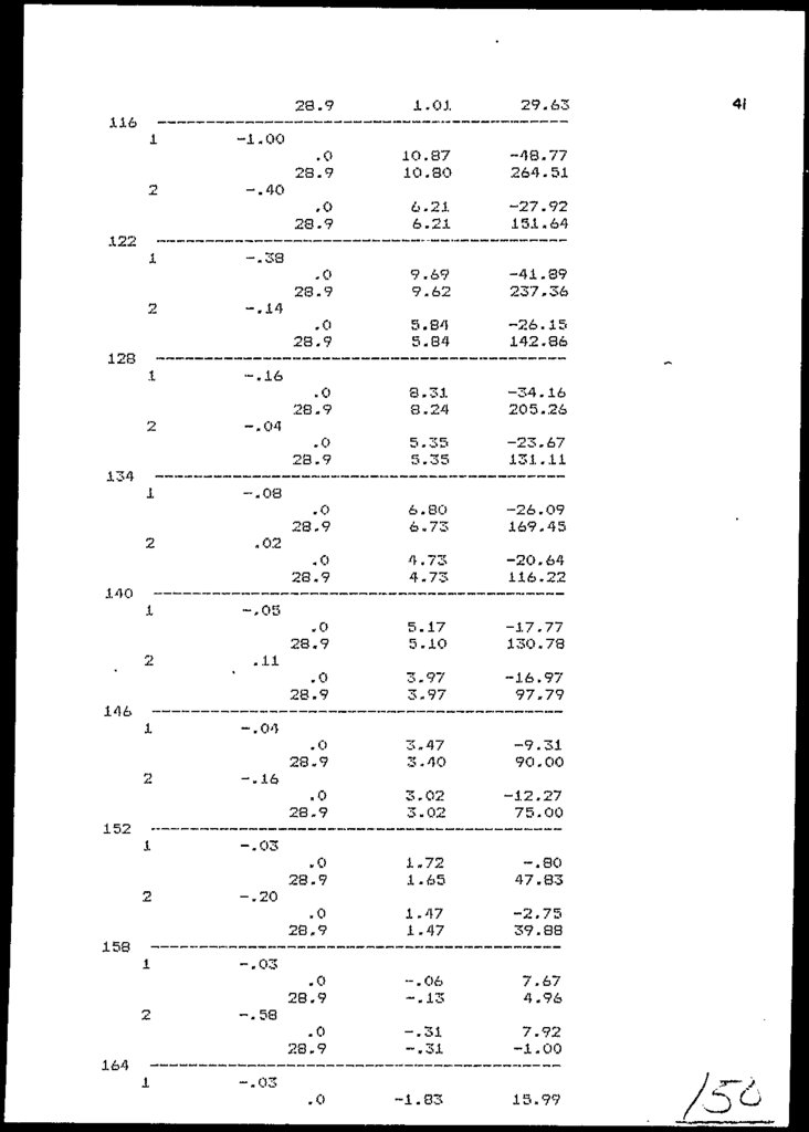
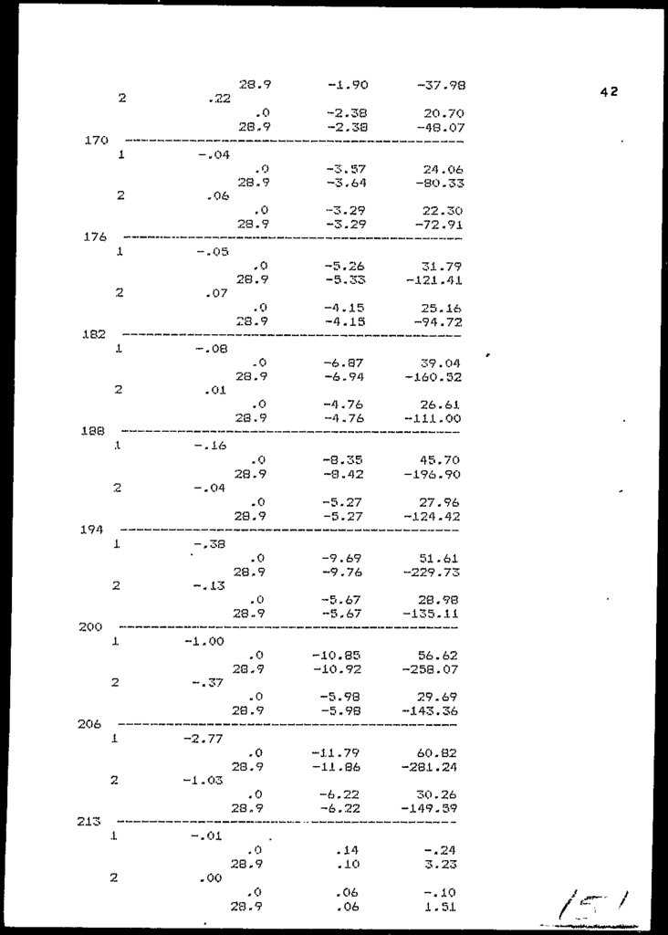
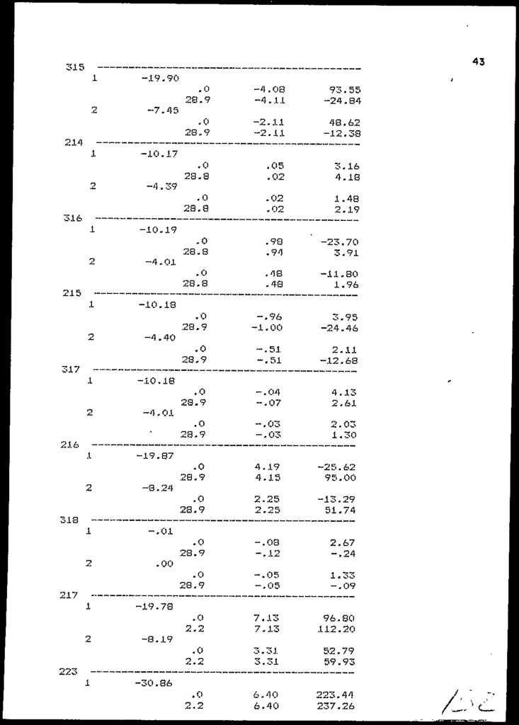
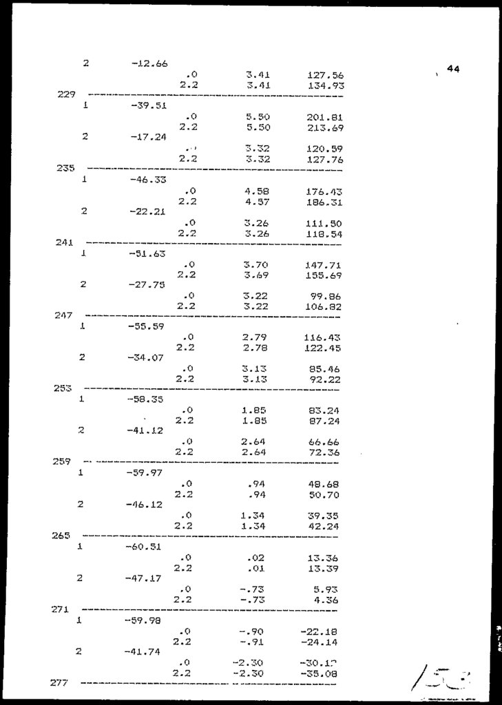
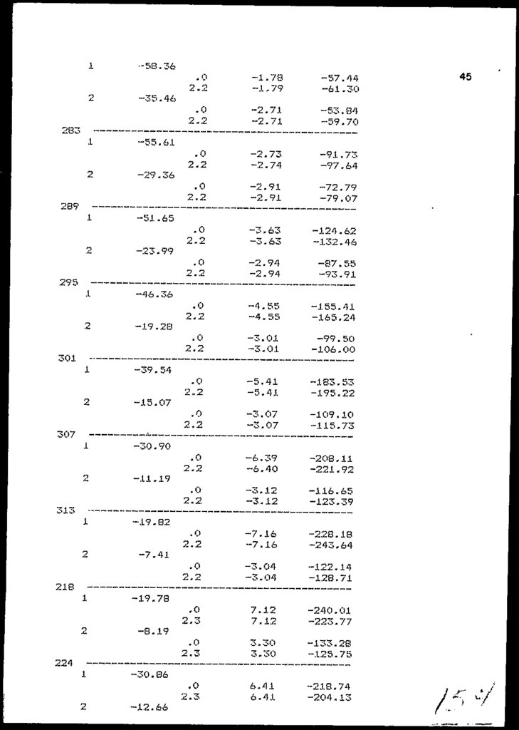
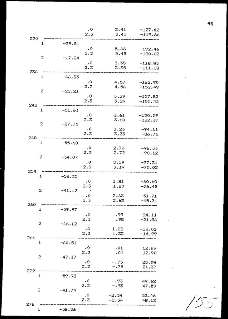
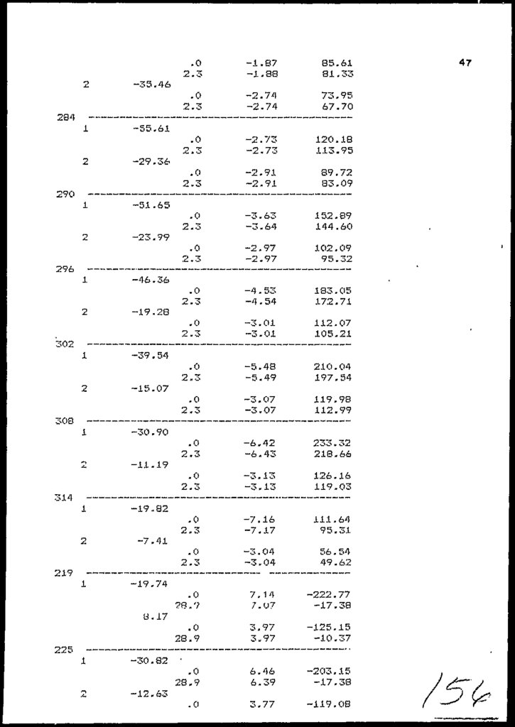
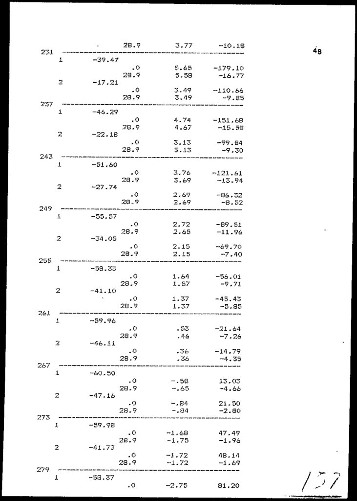
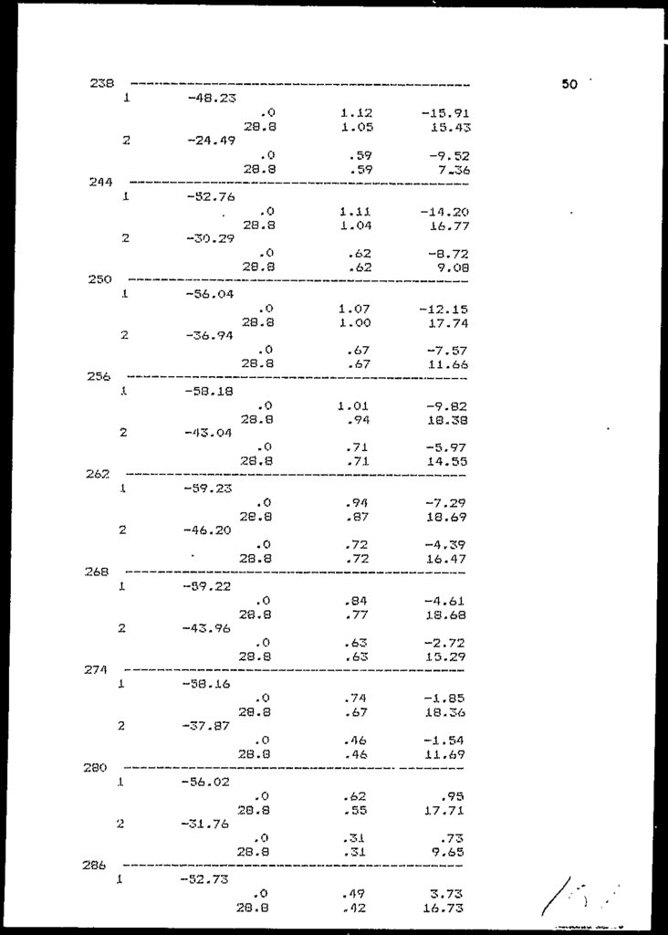
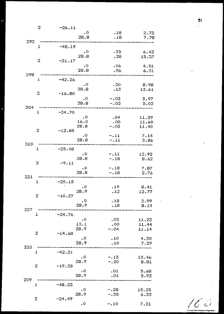
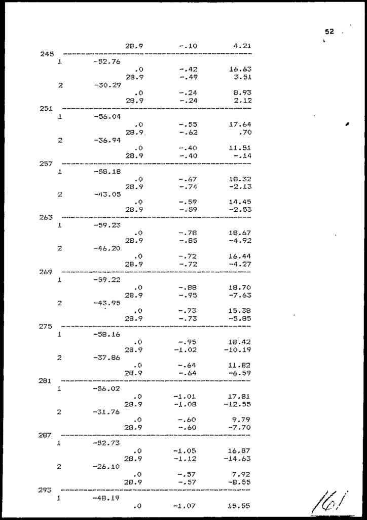
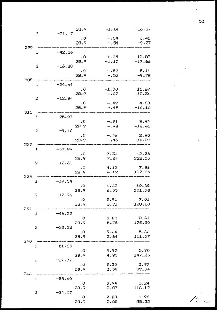
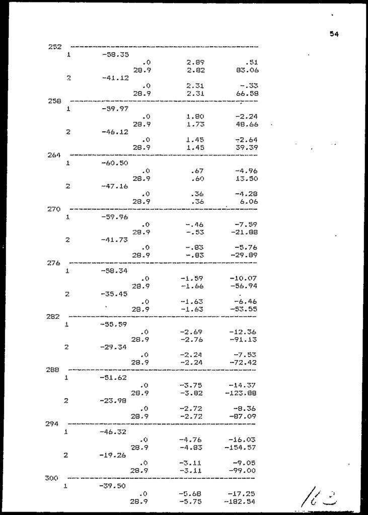
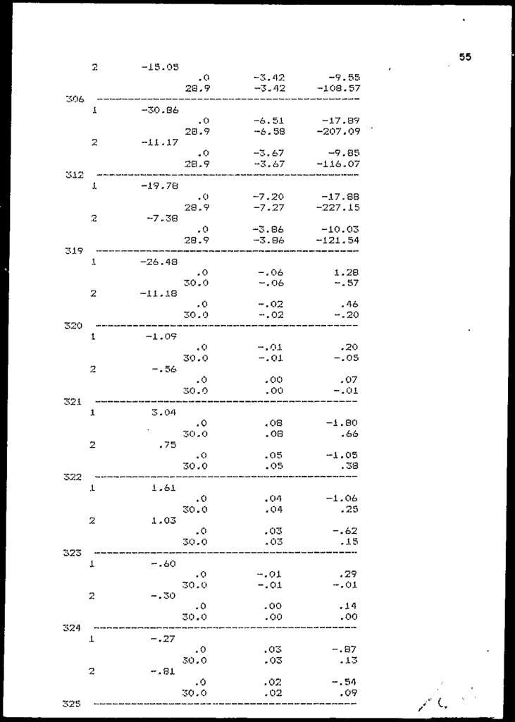
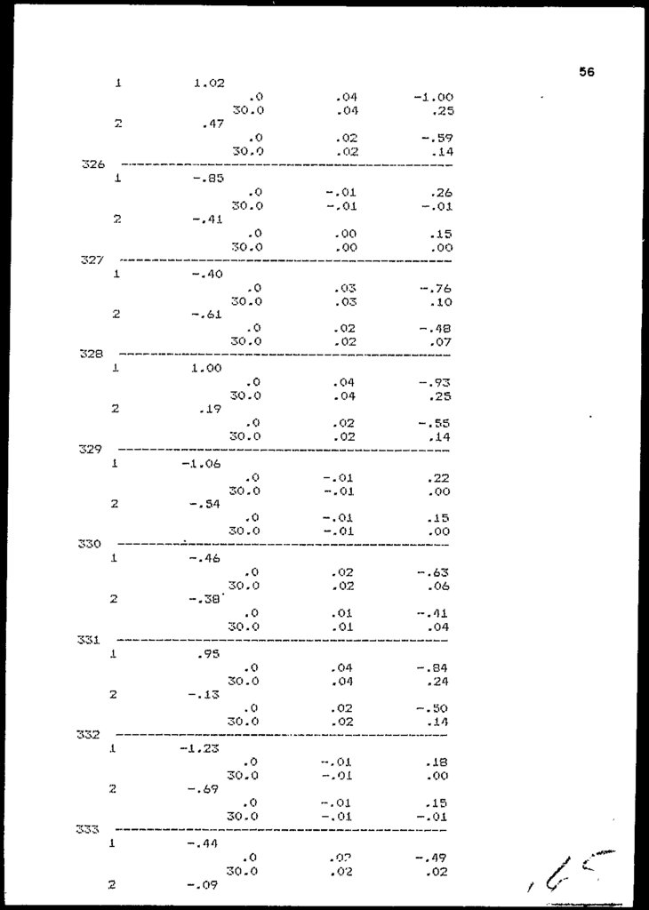
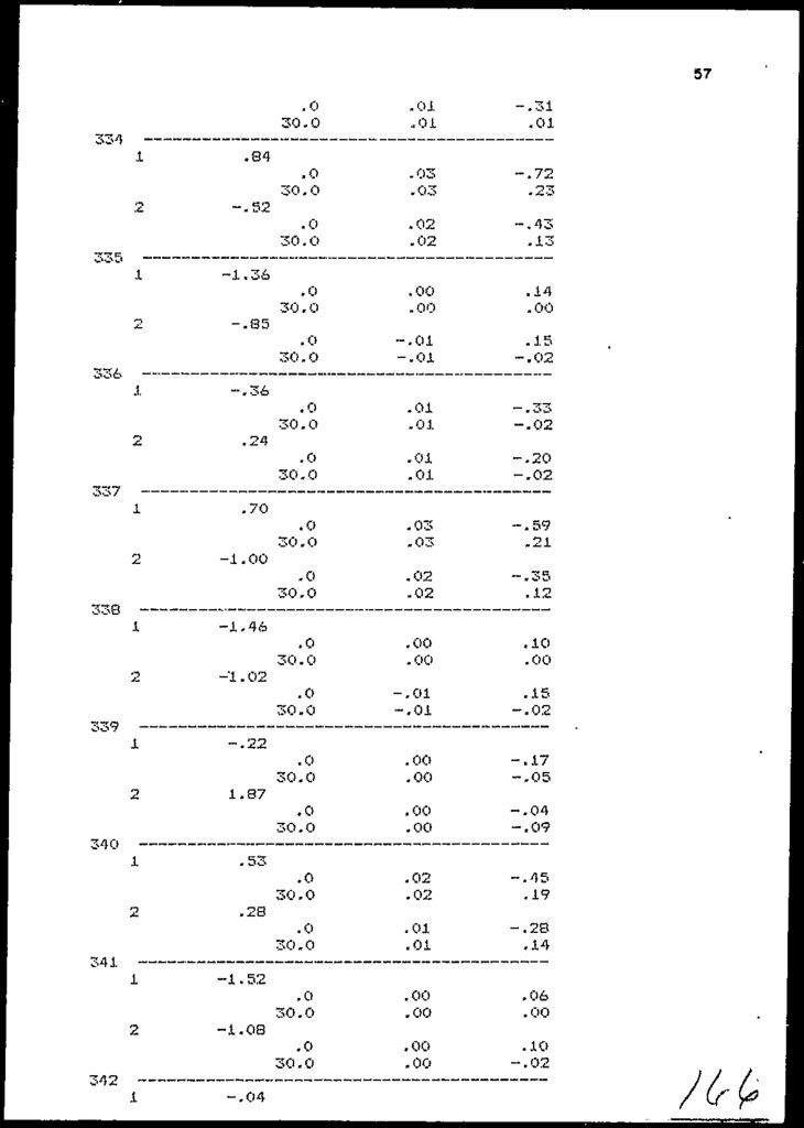
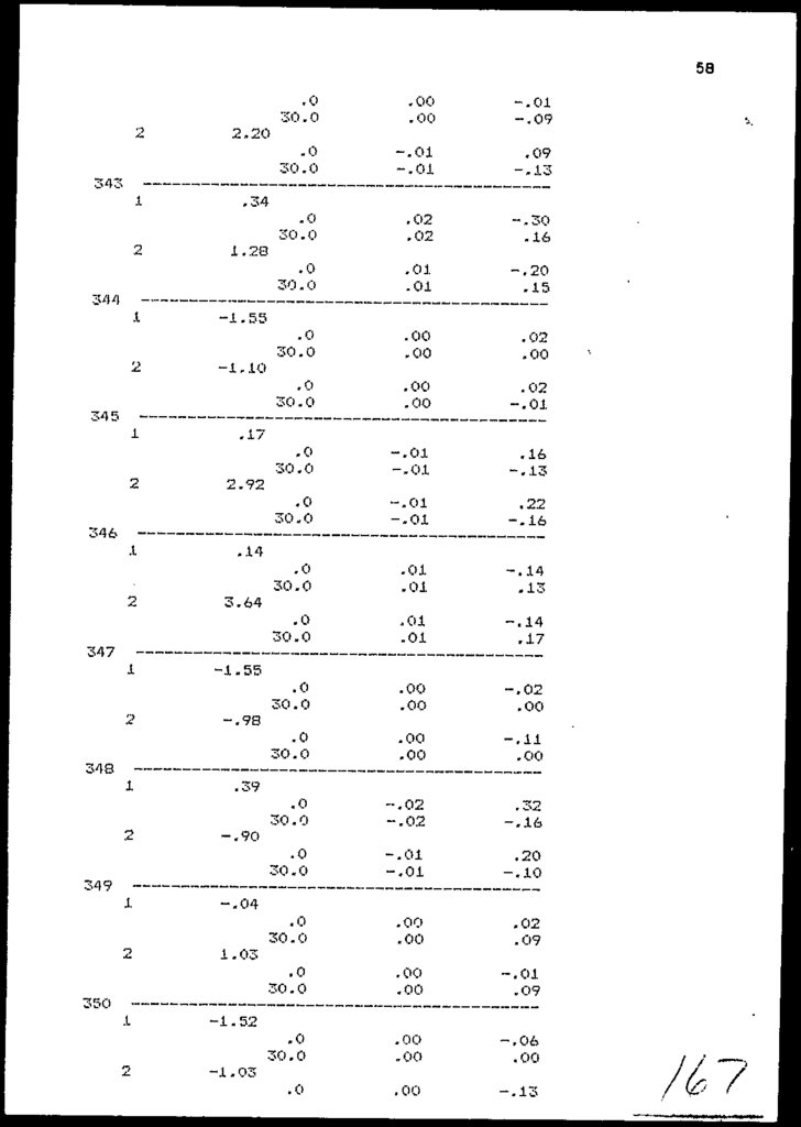
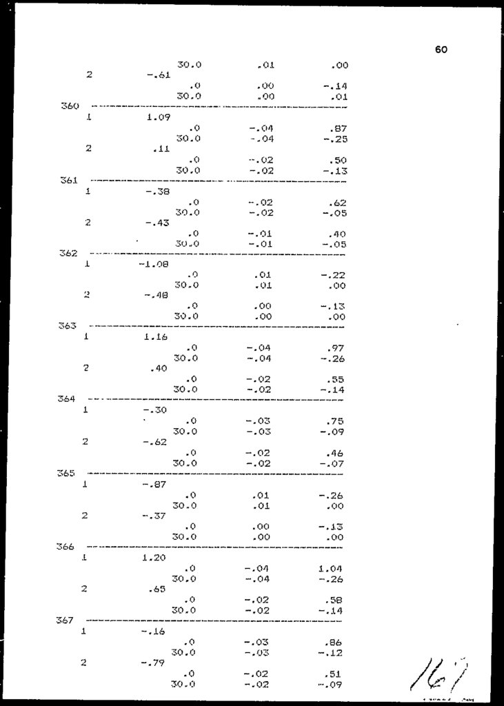
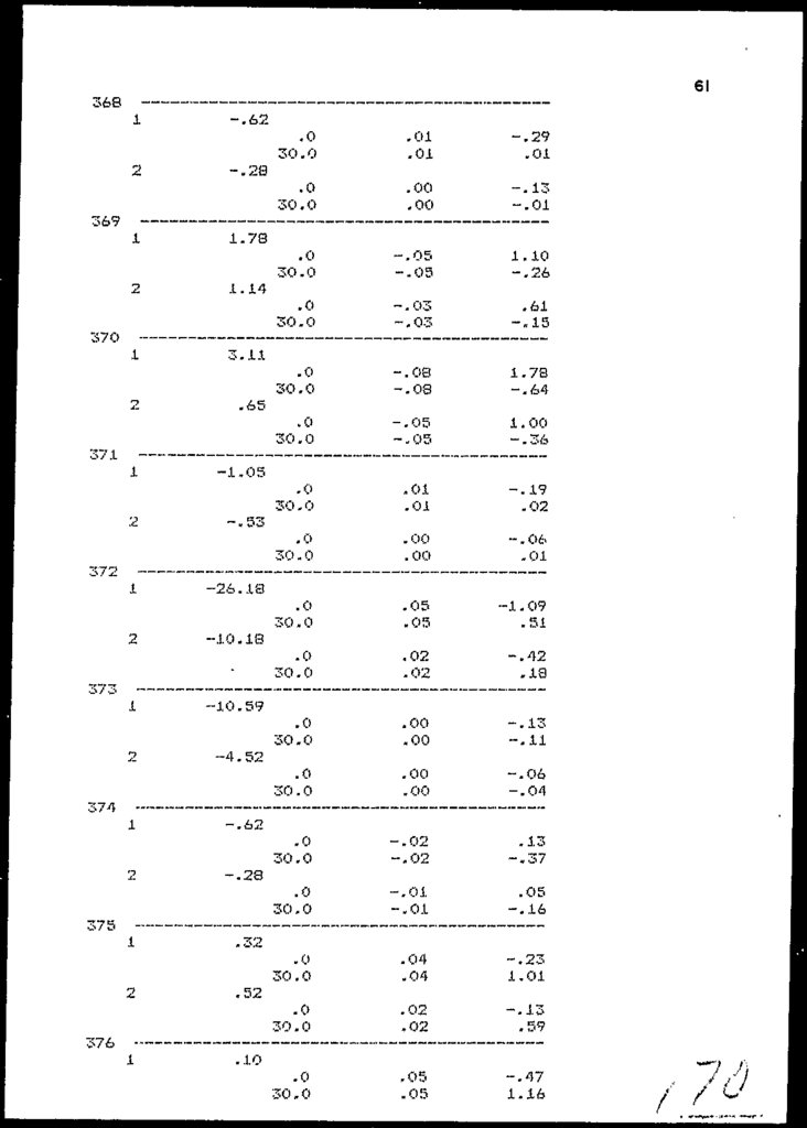
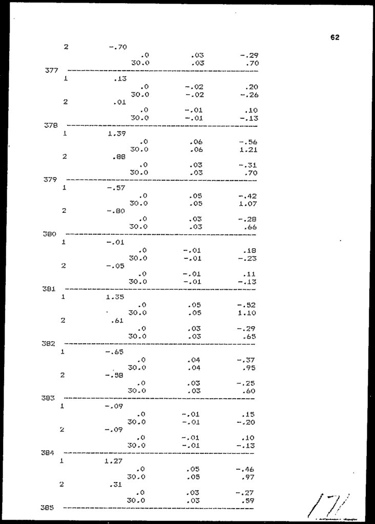
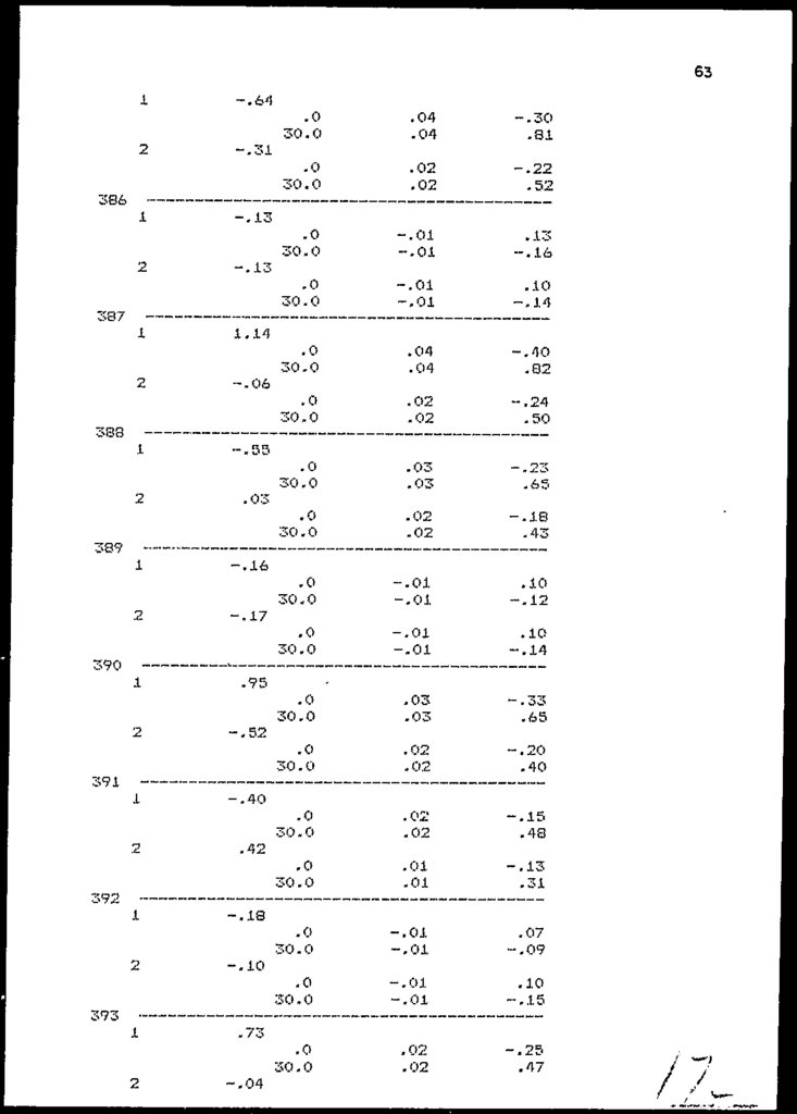
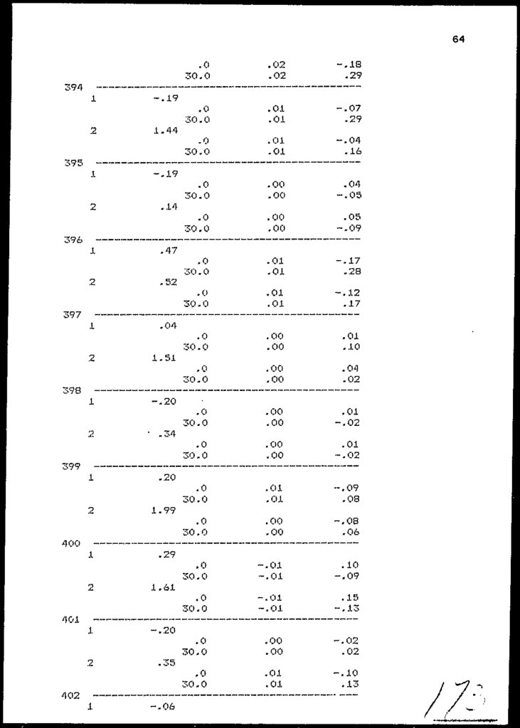
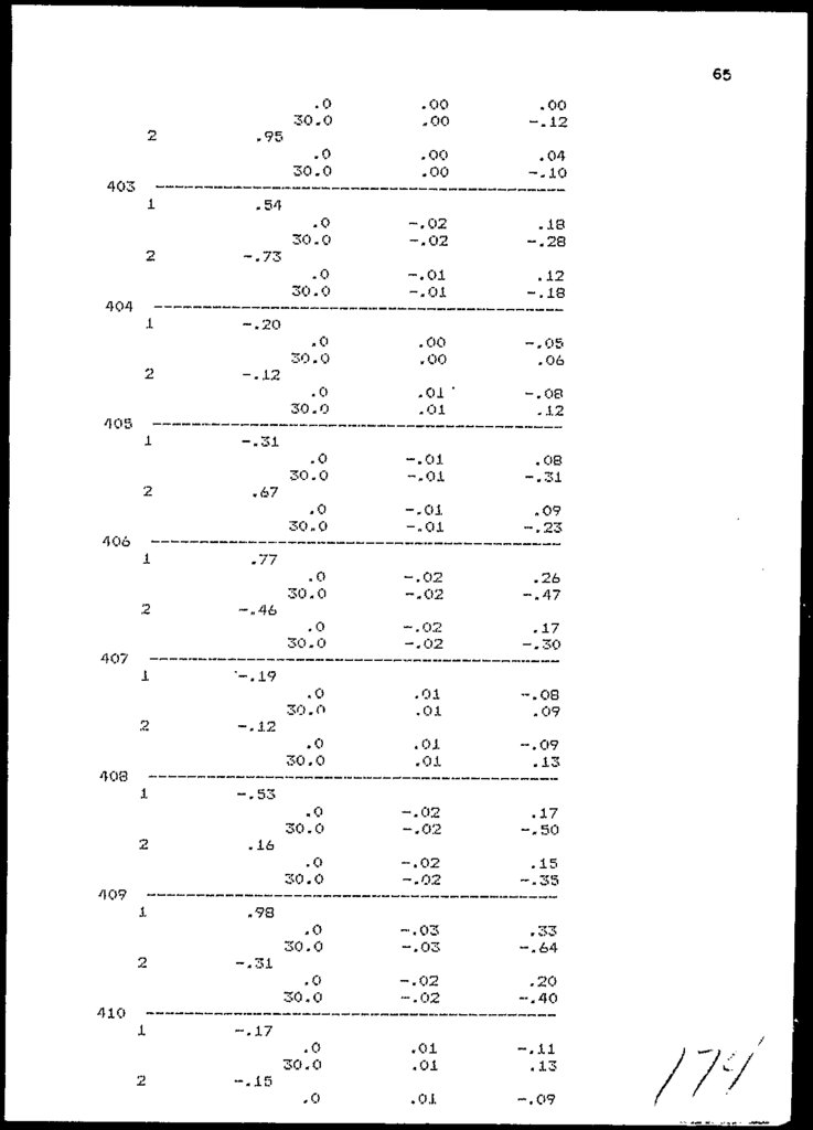
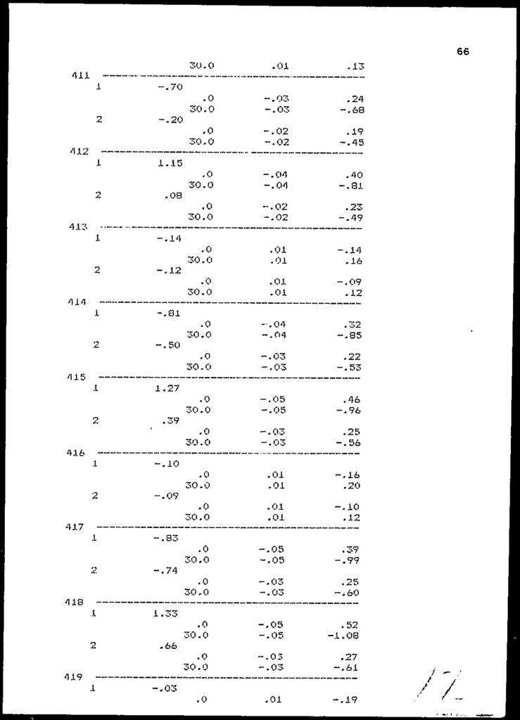
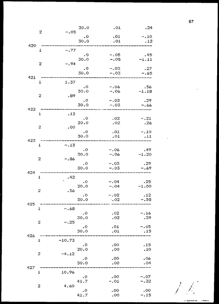
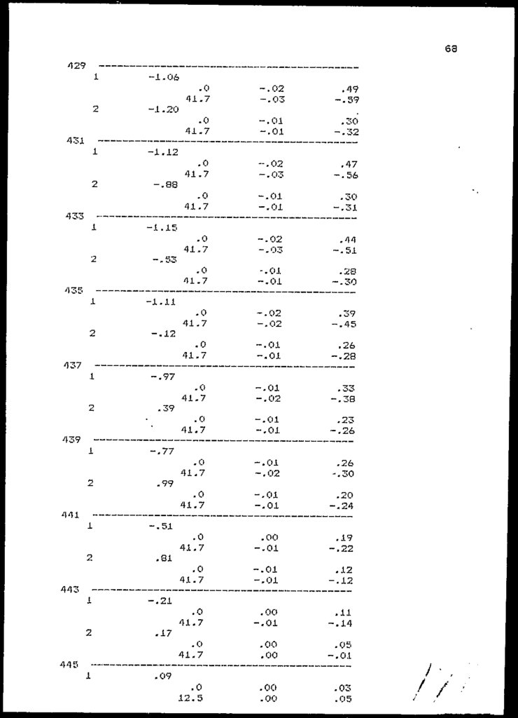
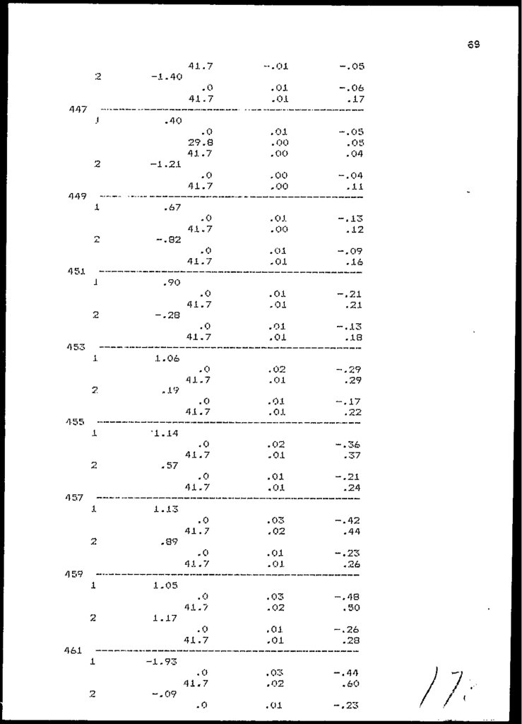
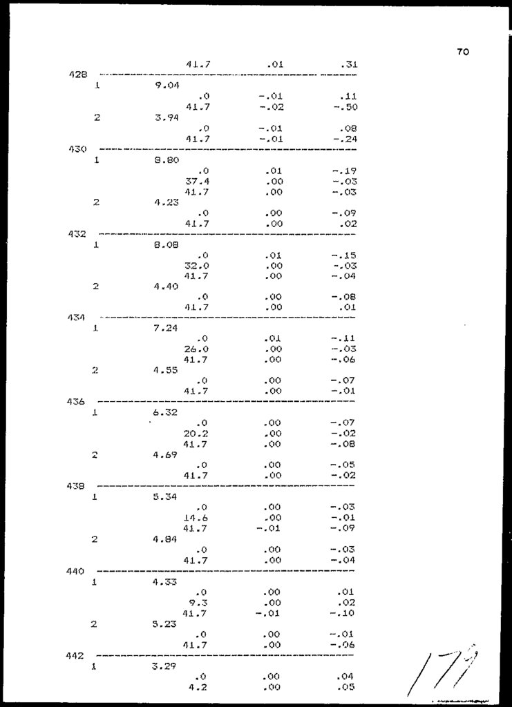
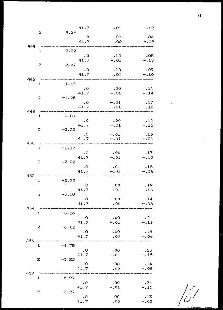
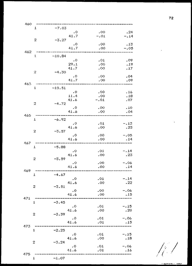
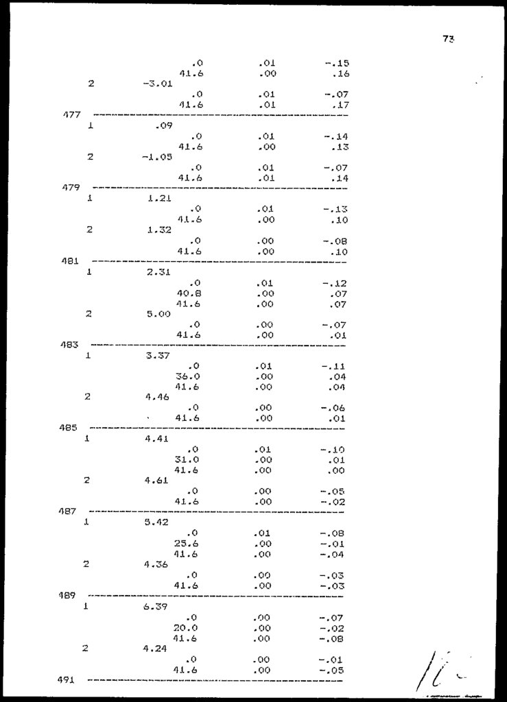
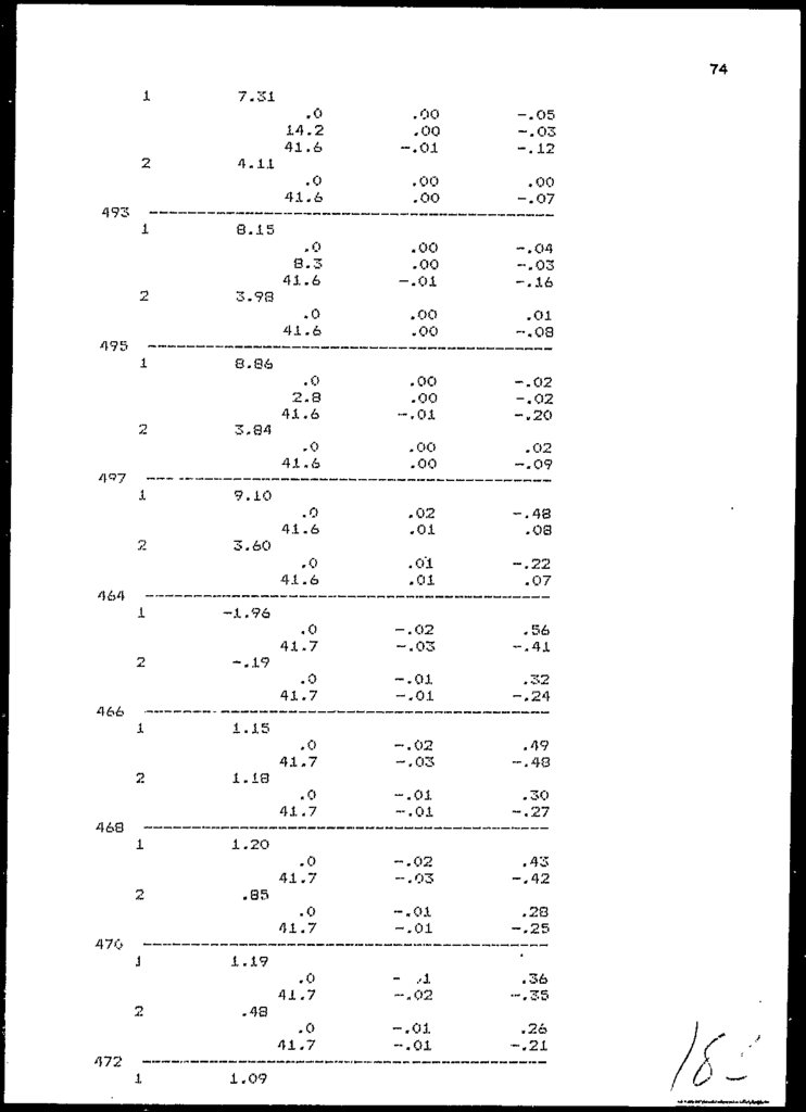
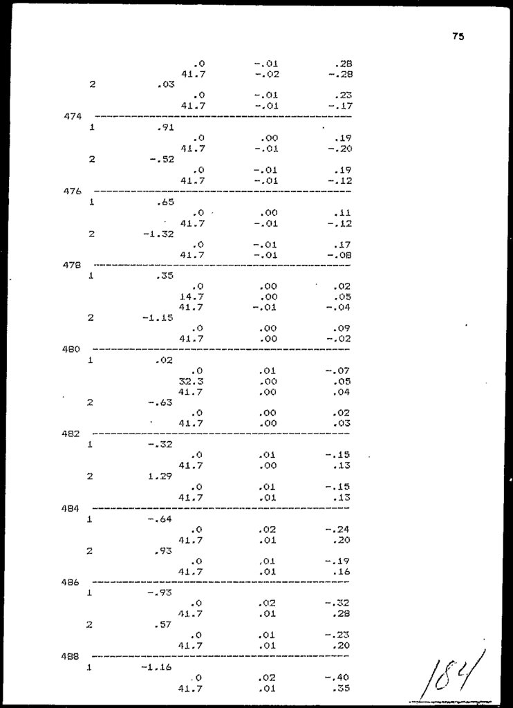
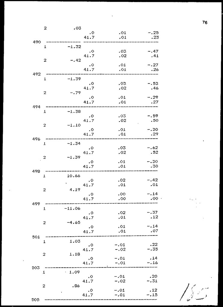
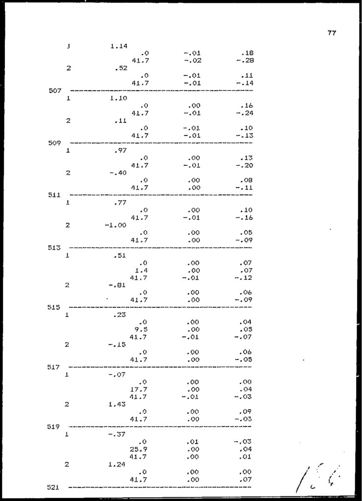
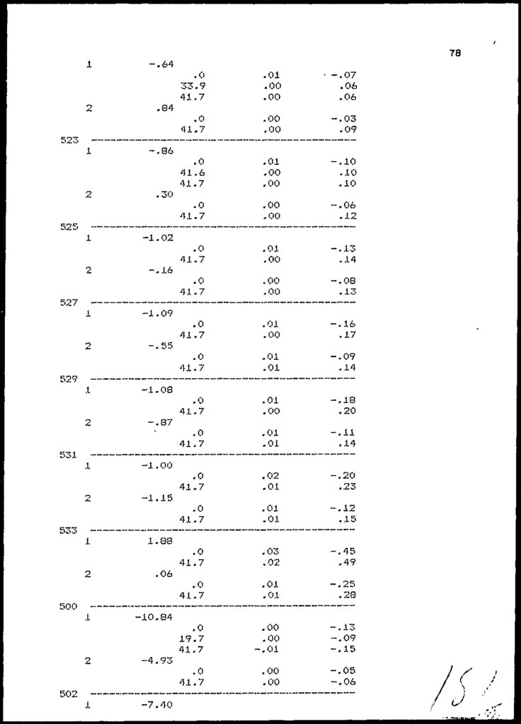
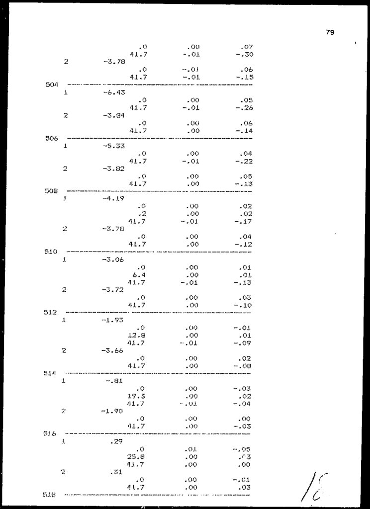
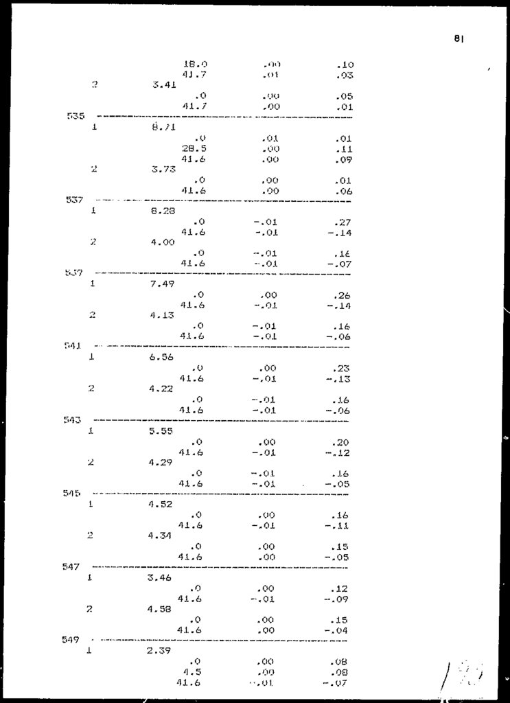
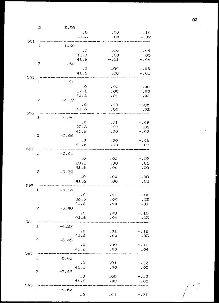
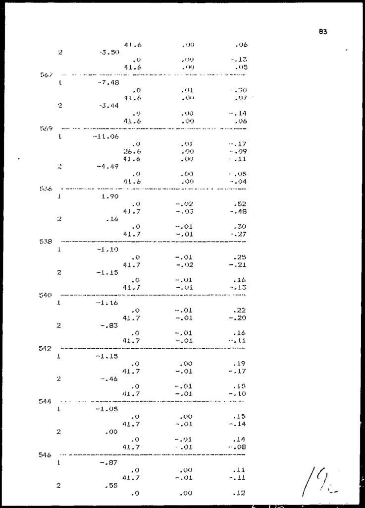
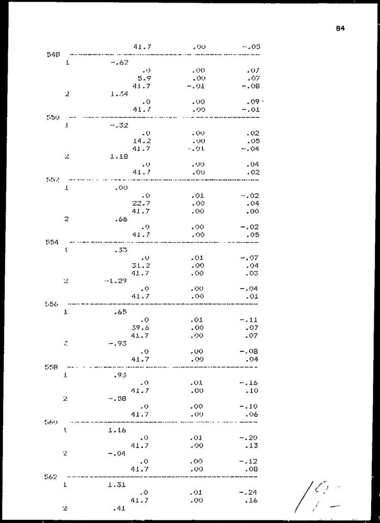
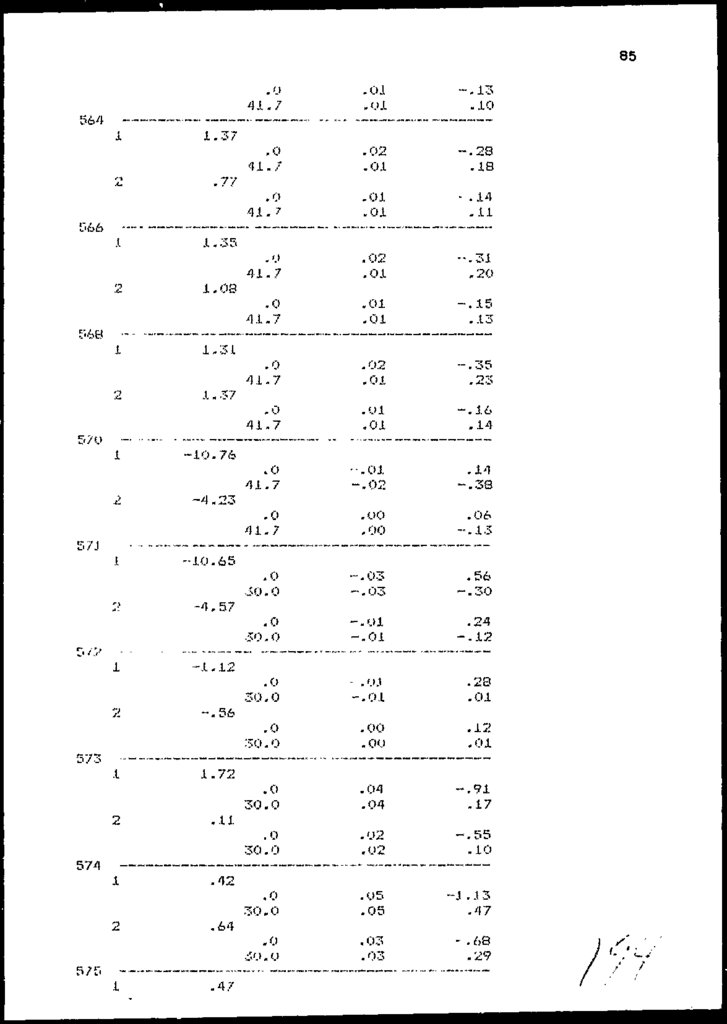
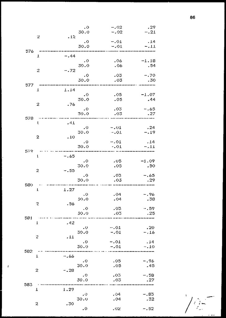
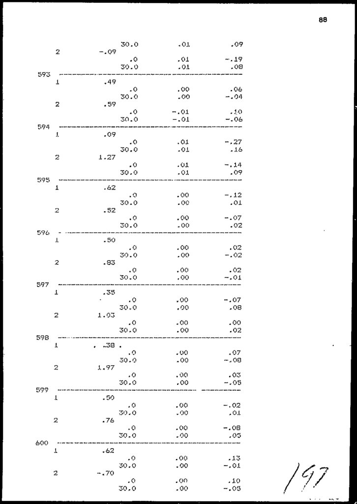
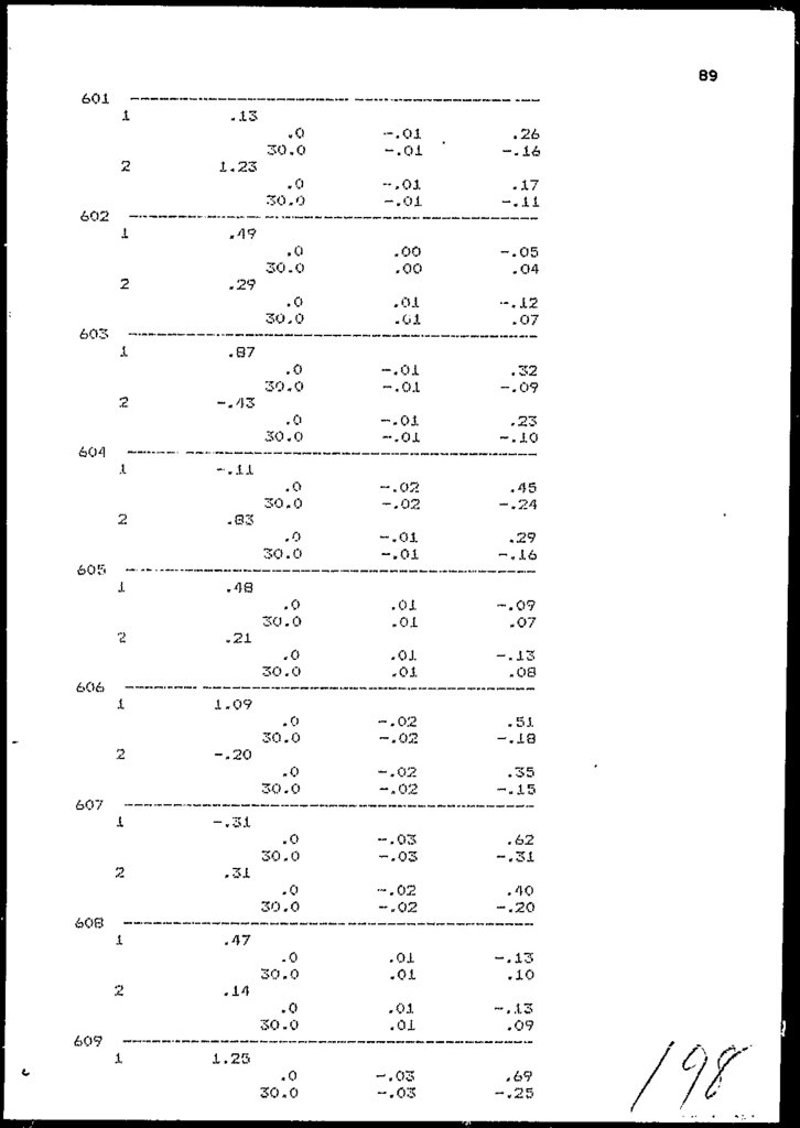
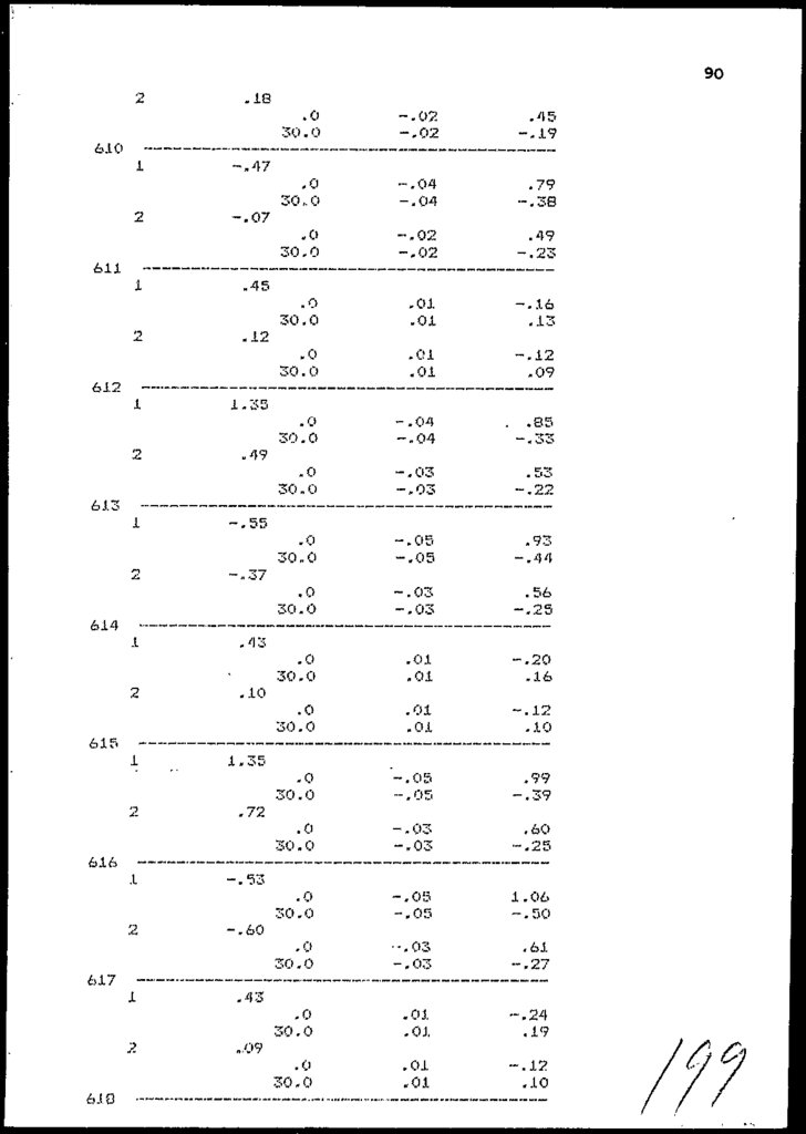
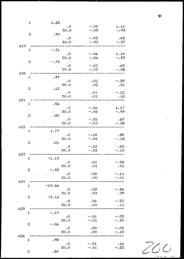
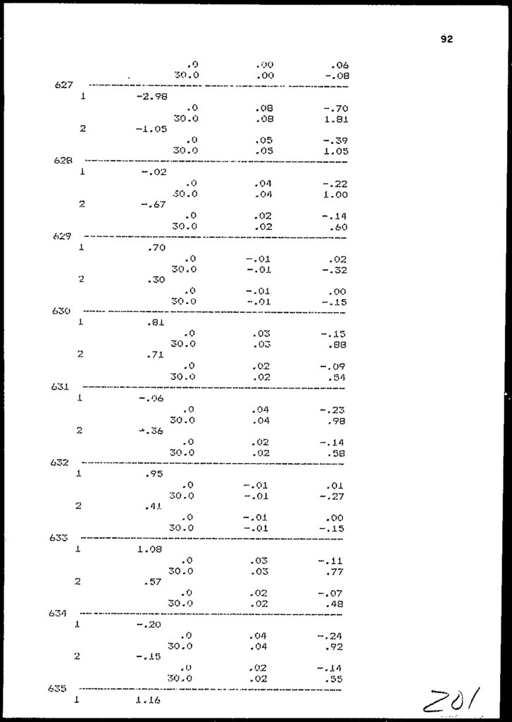
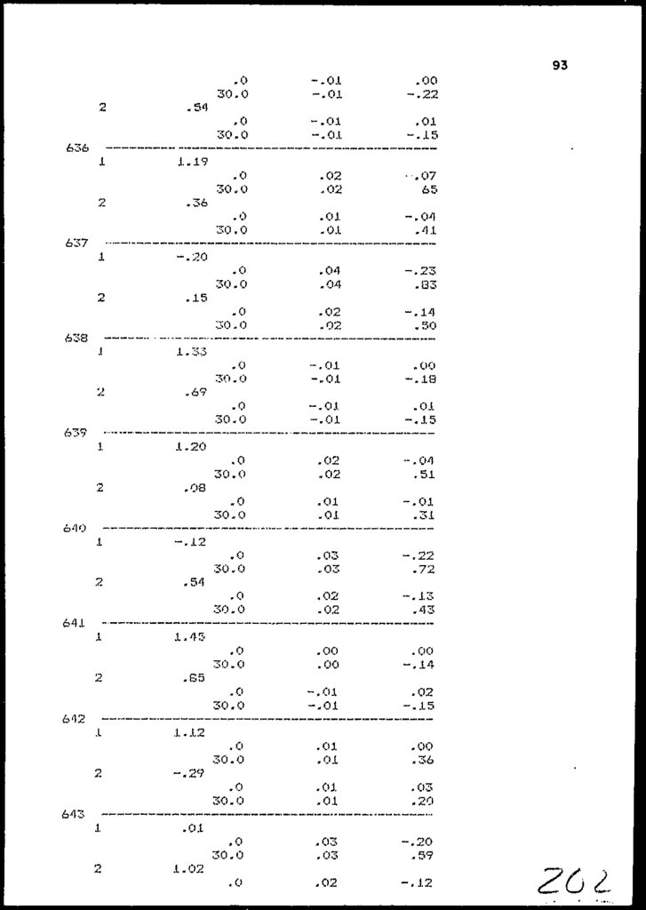
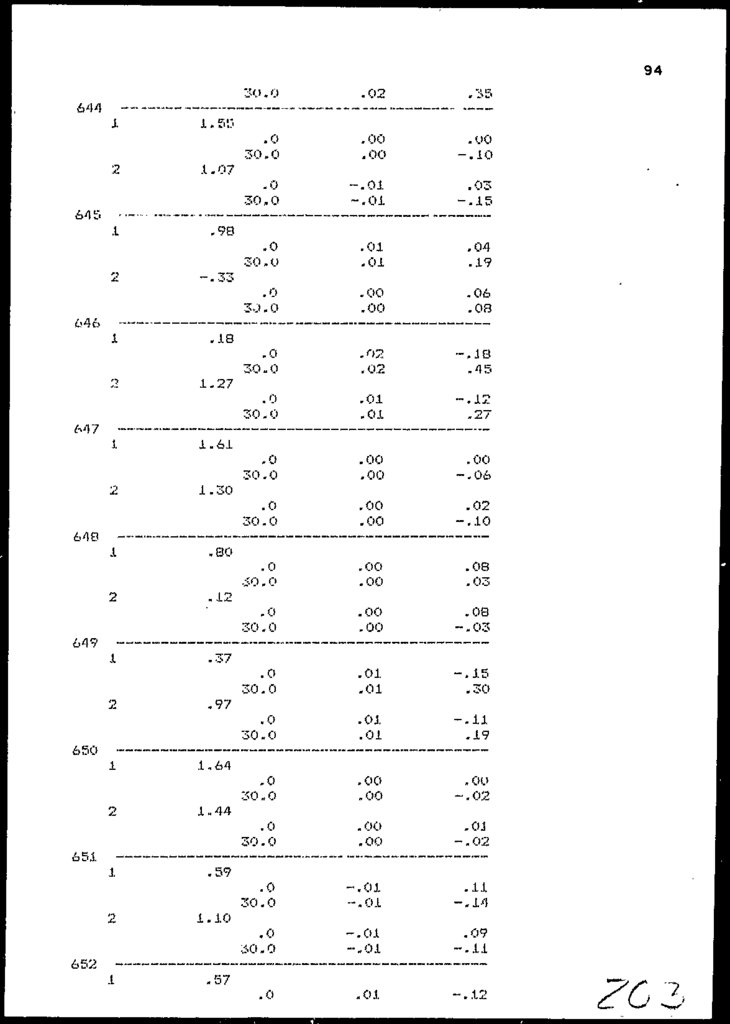
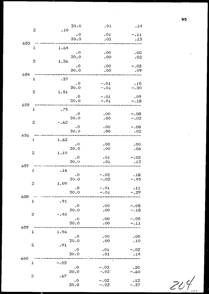
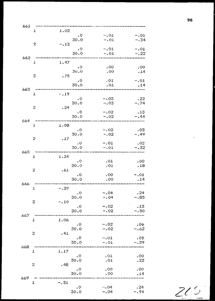
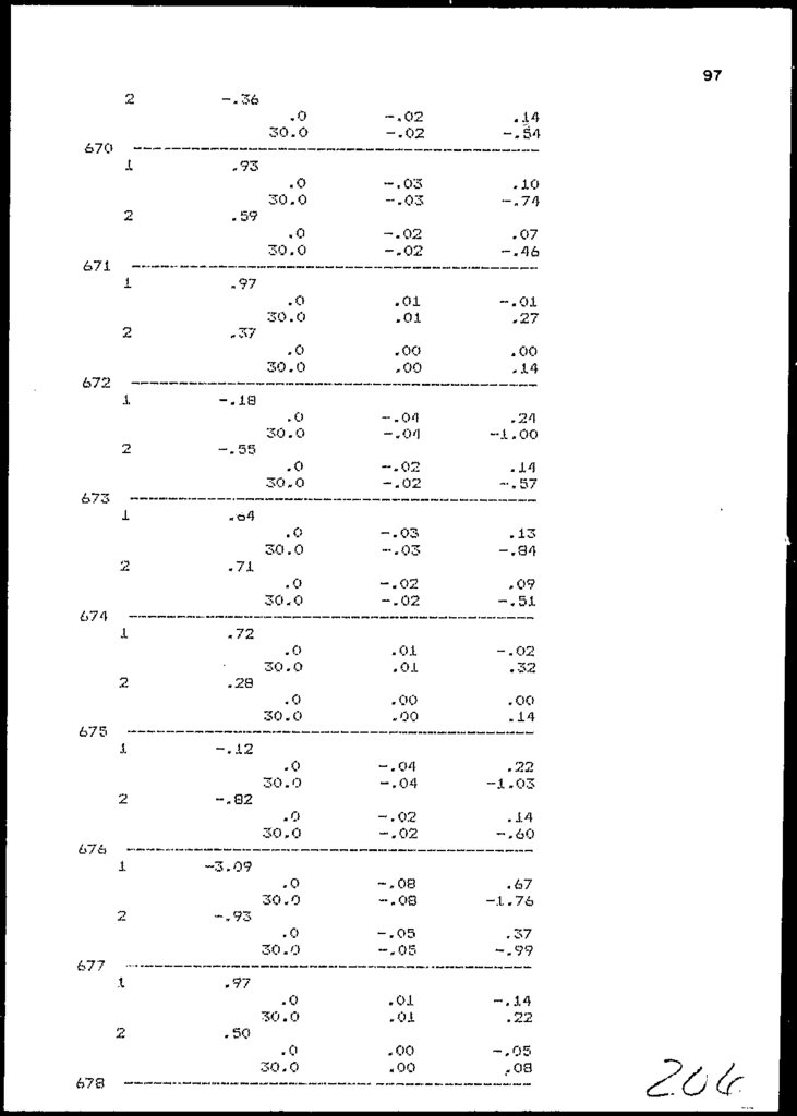
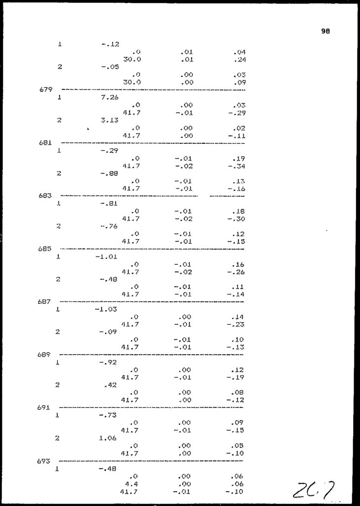
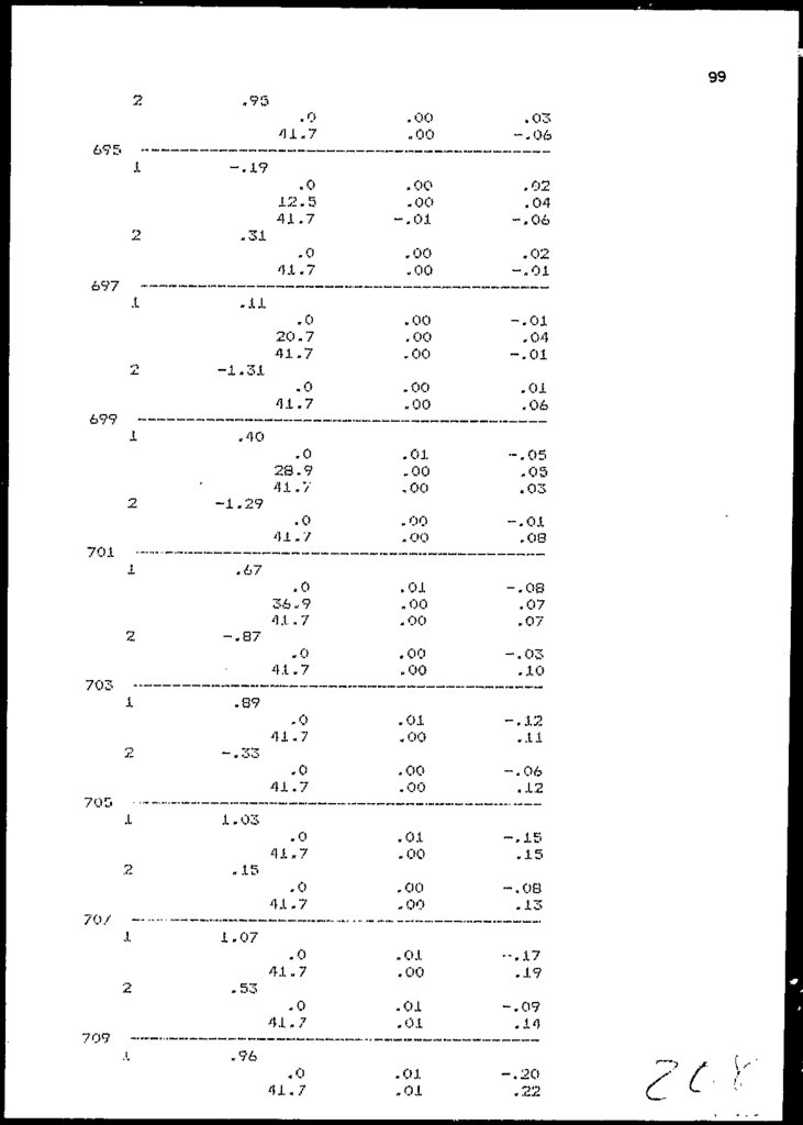
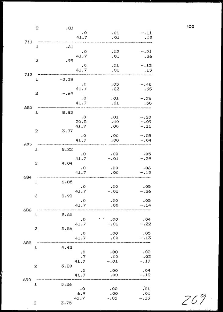
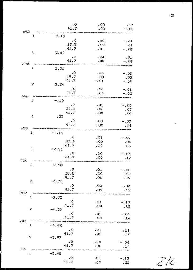
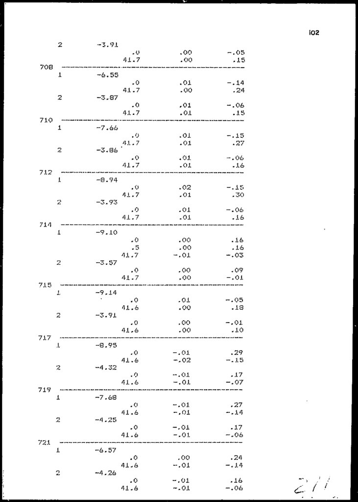
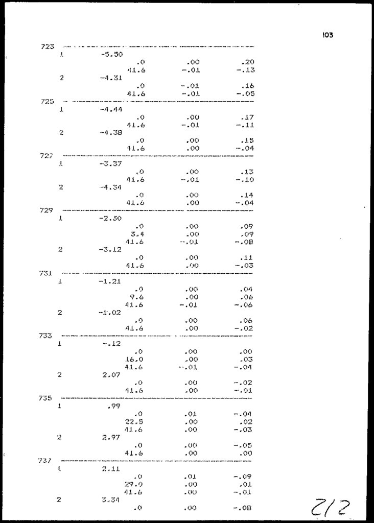
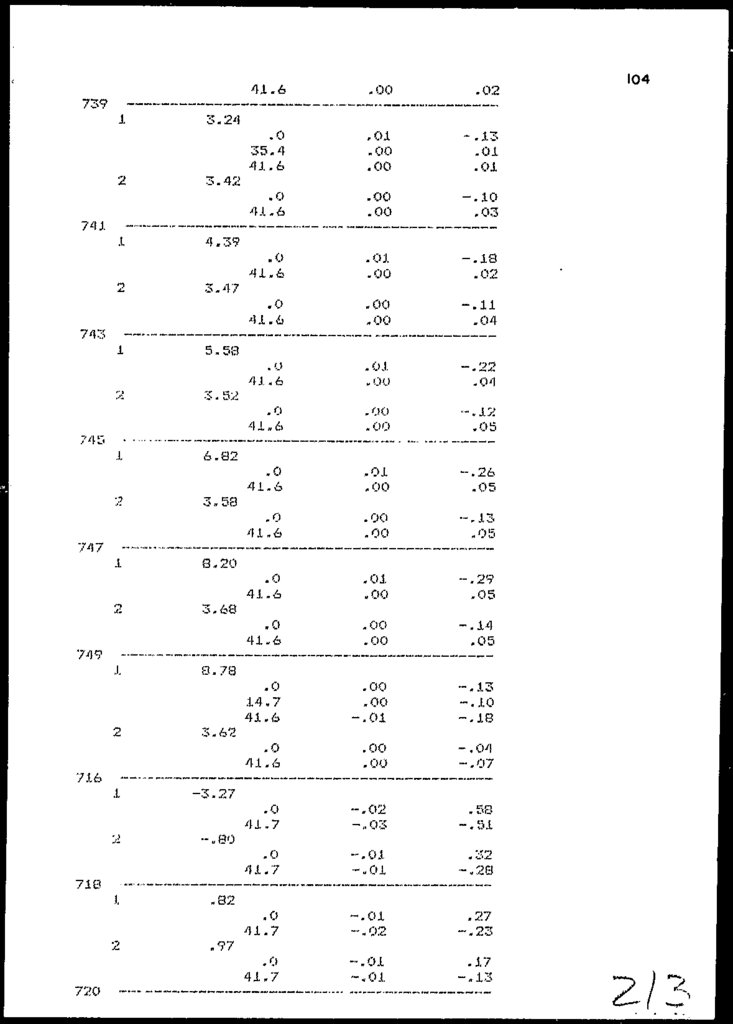
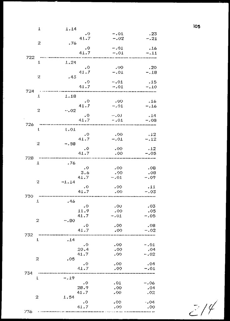
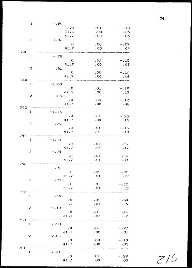
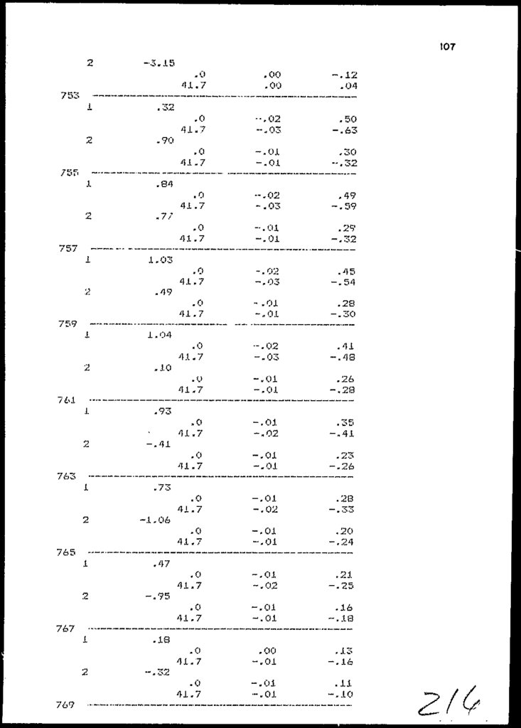
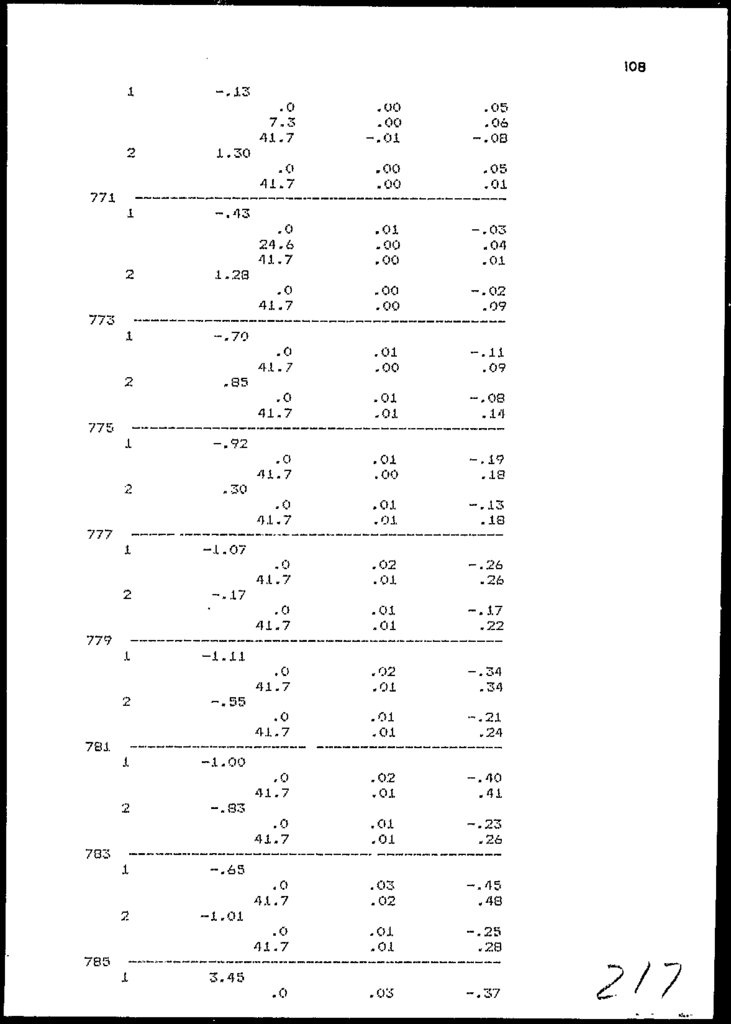
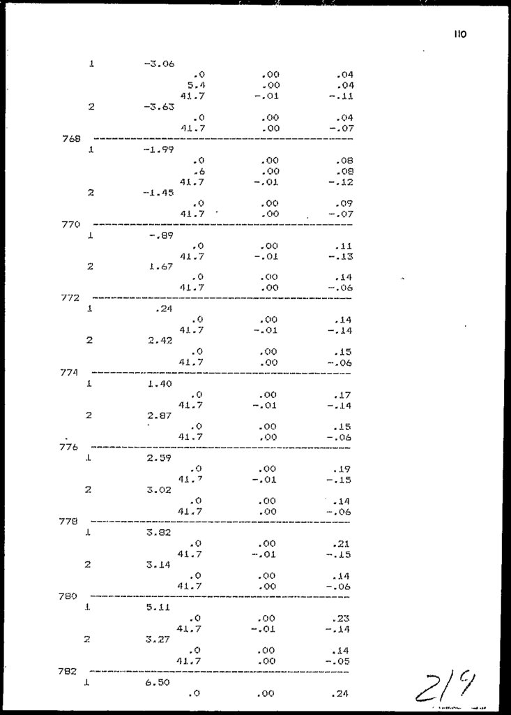
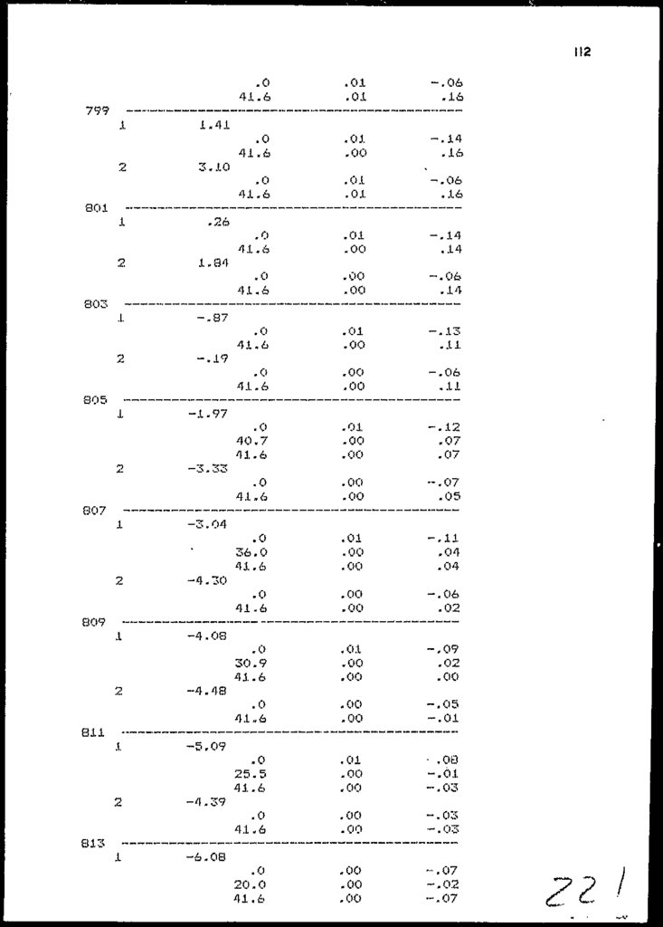
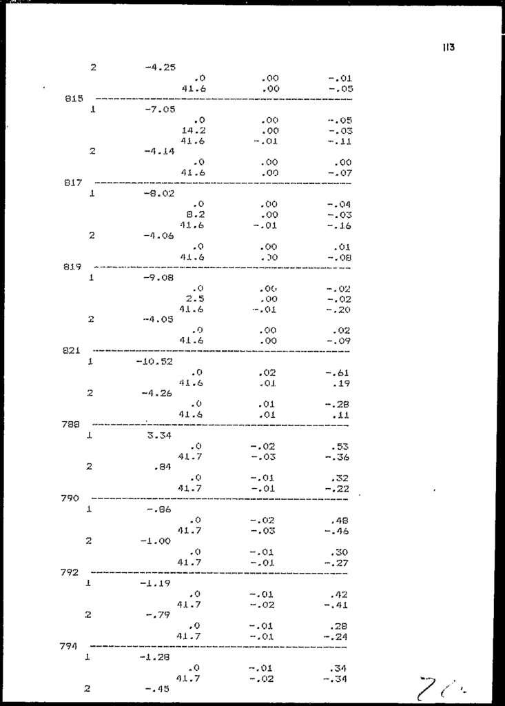
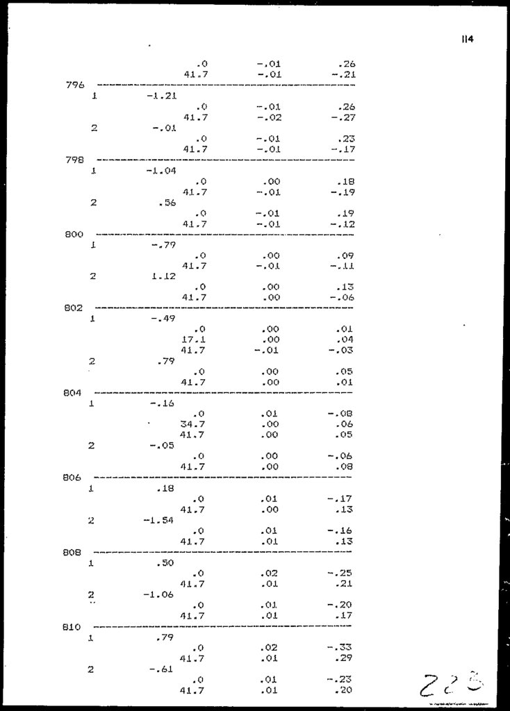
The compiete output of the displacements and rotationsat each joint, (tor the ideal structure; is given in
Appendix-II. The values on Page 1 to 8 inclusive,
correspond to the Dead Load case and on Page 9 to 16
inclusive, correspond to the Live Load case. The total
deflection is the sum of the two.
2.6
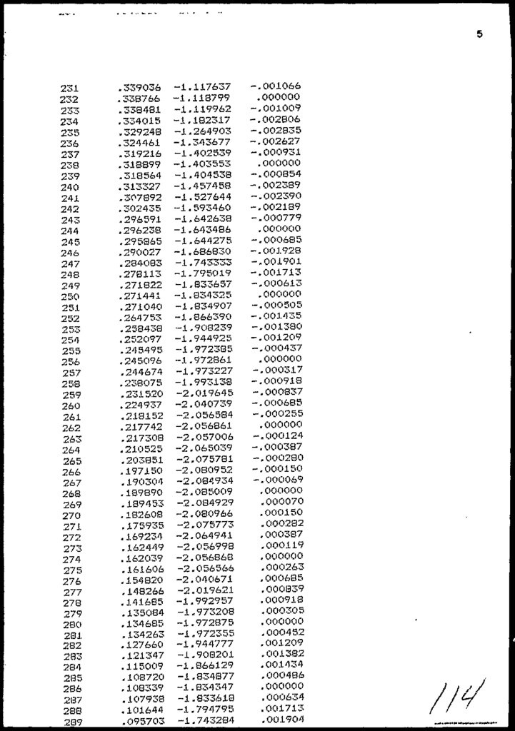
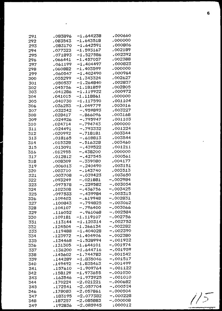
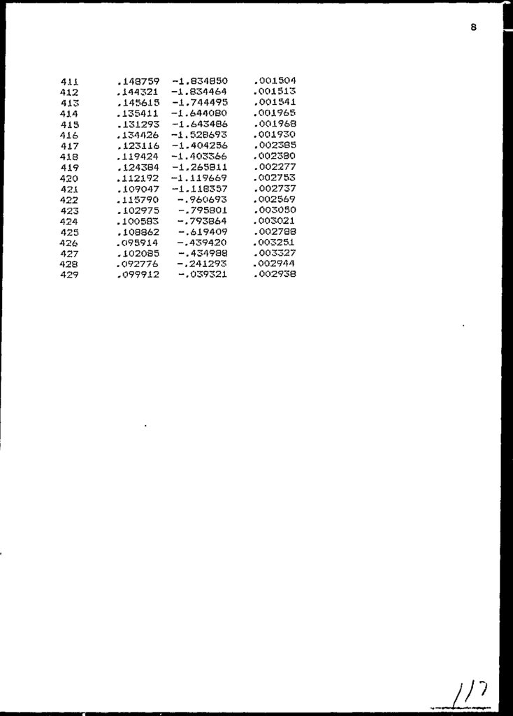
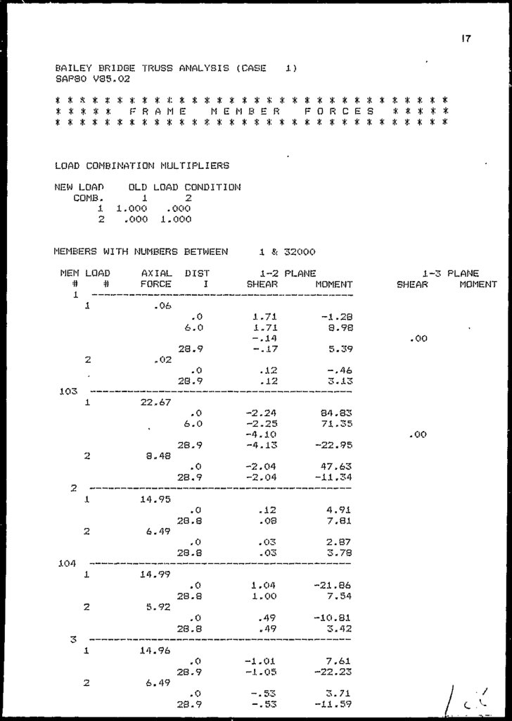
MEMBER FORCES
An output of file F3F
ideal structure as given
provided in Appendix-11
The output should be read
2.8 (for node and element
-ve
+ve
=
=
viz. Member Forces, of the
by the Program in the end is
page 17 to 115 - inclusive.
with reference to figure no.
members;:
compressive force
tensile force
The results of 2 critical panels no. 9 and 1U is shown
in Figure 2.6. The corresponding values for the actual
structure
is
given
in paranthesis. Defiection/ytranslations of critical nodes is provided in Section
2.5 above.
A resume of forces in critical members for case B&C is
provided in Table 2.3 for ready comparison of HS 20 and
H 15 Loading.
2.7
DISCUSSIONS
2.7.1
Observed Deflections
For the result of the analyses to be acceptable, it is
necessary to check the "Translations" in each loading
case - especially the "Y-translations/deflections". In
Section 2.b, observed deflections 1'or the critical
points is shown for both cases (A fit ti), and is found to
be wifchin acceptable limits vis. not exceeding span/300
(= 7.2 inches;. Deflections in case C is lesser.
:.7.2
Limitations of (Jomputer Analyses
Fact remains, however, that a computer model is based
on the idealization of the structure system. Various
options were tried on different models to simulate the
conditions. It is especially for the "reinforced chord
panels" (reinforcement held by collar chord bolts; not
provided
in
the
program to truly
model
that
arrangement. Therefore the actual prevailing forces in
the members can differ, somewhat, from those calculated
by the program.
2-6
24.
r\50
51
52
262
263
264
2.
3.
4.
5.
6.
Member
No.
1.
Sr
No.
9
9
9
9
9
9
. ranel
No.
!
i
i
-do-
-do-
Top Chord
-do-
-do-
Bottom Chord
Location
DL~
60.5
59.0
59.0
'
- 60.5
- 59.0
- 59.0
!
1
—i
-
47.7
45.5
- 45.5
47.7
45.5
45.5
Case
-
-
-
108.2
104.5
104.5
108.2
104.5
104.5
60.5
59.0
59.0
"«-
- 60.5
- 59.0
- 59.0
i
rorces IMDSJ
Summary of Approximate Forces on Critical Chord Memb
TABLE 2.3
19.6
19.6
21.0
19.3
19.3
Case C
LL
- 21.0
-
-
i
!
-
-
-
81.5
78.6
78.6
81.5
78.3
78.3
Total
25.
FIG.2.2
PNAMC, MAQNf
f^-^wtpm-
'••*" —^H
N'K^ i
END ELEVATION
X-SECTION
26.
KEY ELEVATION OF BRIDGE STRUCTUREFIG-
27.
\JHALF COMP'
28.
cH
m
;o
o
o
o
>
00
m
CO
CO
l
29.
30.
FIG. 2.4REFERNCE AXES
31.
V.ELEV. OF TYP PANEL TRUSS
FIG. 2-5
PANEL, TRUSS
BAILEY BRIDGE
JOB NO. 295
Drawn.
Dale.
APRIL, I99O.
32.
FIG. 2 6HIGHWAY DHIDOES
H92CM4
8,000 LB9.
32000 LBS*
32.000 LBS*
°h—i
-{roD—
W » COMBINED WEIGHT ON THE FIRST TWO AXLES WHICH IS THE SAME
AS FOR THE CORRESPONDING H (M) TRUCK.
V • VARIABLE SPACING — 1< FEET TO 30 FEET INCLUSIVE/ SPACING TO BE
USED IS THAT WHICH PRODUCES MAXIMUM STRESSES.
CLEARANCE AND
jOAD LANE WIDTH ,
2'-0"
B'-Q"
Figure
SUiidurd IIS Truck
(HS-20)
33.
47 49SO
55
55
L. 1.
L. L.
D. L.
LOAD AT 6"
FROM NODE No.
PANEL NO.
3 .84
O .64
3 20
1 .85
43
8
5 .76
O. 96
4.80
1. 85
49
9
9 60
1.60
8. OO
1.85
55
10
1.44
O.24
1 20
1 85
61
11
0.96
0.16
0.8O
1,85
67
12
LOADING FONTS. MAGNITUDE AND DISTRIBUTION
OF THE HS - 20 TRUCK
L.T.
Go)
56
59 61
NOTES
(fi)
65
67
(12)
F"IG. 2.7
68
D.L.
Live load due to HS-20 Truck
Impact Load
Dead Loads, excluding self wt. of truss
members
L.I.
Totai of D.L. + L.L. + L.I. (given in
the input)
L.L.
L.T.
All loads in Kips.
34.
• VALUE GIVES TOTAL FORCEDL+LL+ I FOR CASE A
• VALUES IN PARENTHESIS GIVES
TOTAL FORCE FOR CASE B
FIGURES ENCIRCLED INDICATES
THE MEMBER NUMBER
PANEL 10
CENTRE OF STRUCTURE
, FEATURE SYMMETRIC
ABOUT THIS LINE
FIG.2-.8
TOTAL MEMBER FORCES IN KIPS
BAILEY BRIDGE PANEL 9 6 IO
NAME OF FILE
STRUCTI/J
DESIGNED. SMW
DATE. SEPTEMBER I99O-
35.
FIG. 2-9H 16-44
9,000 IBS.
24,000 LB9.
W = TOTAL WEIGHT OF
TRUCK AND LOAD
CLEARANCE AND
LOAD LANE WIDTH
10MT
CUHB
2'-0"
6'-0"
2'-0"
FIGURE HIS TRUCK
?c
36.
CHAPTER - 3LOAD TESTING OF BRIDGE PANELS
37.
LOAD TESTING OF BRIDBE PANELS3.1
PREAMBLE
As required in the Agreement, three representative
panels, used ir> the construction of the structure, were
obtained from the launch nose assembly,, from Pewshawar
and transported to Lahore for load testing.
Testing of these panels was entrusted to the lest Floor
of Civil Engineering Department Laboratory
University
of Engineering and Iechnology, Lahore.
I wo tests were
conducted:
in
A.
Single panel loaded at the top chord as shown
Figure 3.8 ('lest No.l)
B.
Two panels tested simultaneously in compound form
as shown in Figure 3.10 (Vest No.2)„
The entire process o1 preparation of panels
and
performance
of
testing was conducted under
the
supervision of Chief Testing Engineer. Further, Project
Advisor, Project Manager and Material. Expert witnessed
the testing.
Prior to the undertaking of the actual
testing,
analyses of an isolated panel were performed in the
office for each case. The modelling was done in the
manner and style, in which the actual testing was dnne
in each case. This enabled to anticipate the memebrs
strains and stresses and defected shapes of the
panels.
This chapter explains, the in tent/purpose of the study,
describes approach and method adopted in performance of
each
test,
explains
various
operations
done,
precautionary measures adopted, procedure of testing
and includes the comparison of the theoretical and
experimental strains produced in the components under
the panel loading. J.ri the end, a detailed "Discussion
of the Results" is presented.
3-1
38.
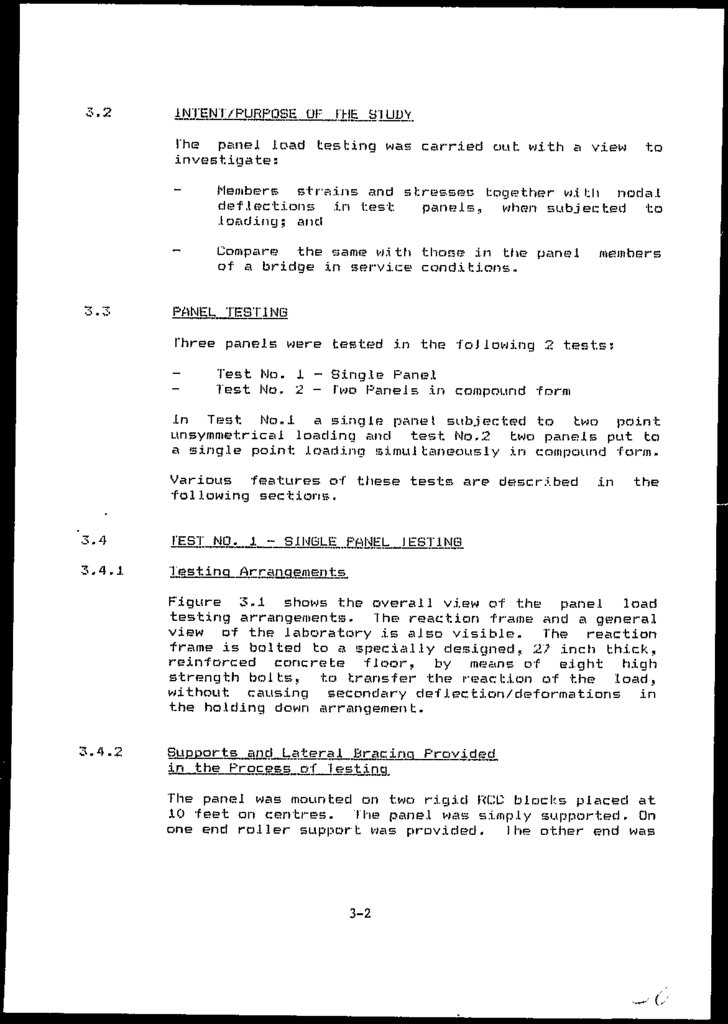
3.2The panel load testing was carried out with a view
investigate:
to
Members strains and stresses together with nodal
deflections in test.
panels, when subjected to
loading; and
-
;. 3
Compare the same w.i th those in the panel
of a bridge in service conditions.
members
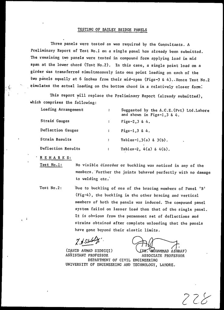
PANEL TESTING
Three panels were tested in the -following 2 tests:
Test No. i - Single Panel
Test No. 2 - Two Panels in compound form
In Test No«i a single panel subjected to two point
unsy/nmetrical loading and test No.2 two panels put to
a single point loading simultaneously in compound form.
Various features of these tests are described
following sections.
3.4
1'EST NO. i
3.4.1
Test ing A r r an_g_emenj:s_
SlNOiLE PANEL
in
the
IEST1NG
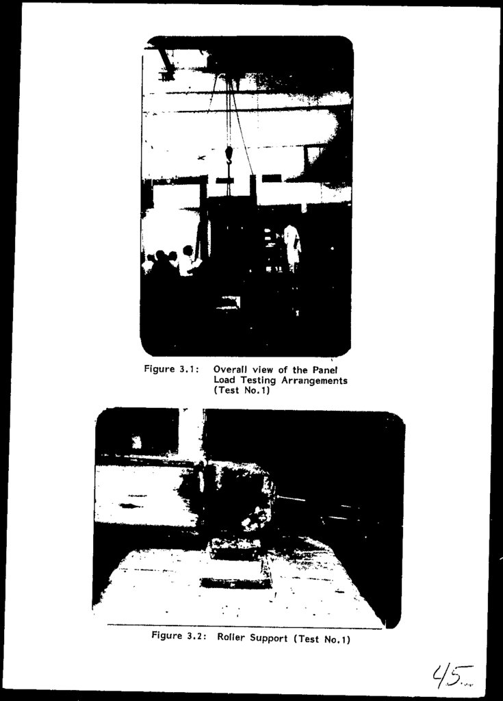
Figure 3.1 shows the overall view of the panel load
testing arrangements. The reaction frame arid a general
view of the laboratory is also visible. The reaction
frame is bolted to a specially designed, 27 inch thick,
reinforced concrete floor, by means of eight high
strength bolts, to transfer the reaction of the load,
without causing secondary deflection/deformations in
the holding down arrangement.
3.4.2
Supports, andr,Lateral_ Brae ing Provided
in the Process of
The panel was mounted on two rigid RCC blocks placed at
10 feet on centres. The panel was simply supported. On
one end roller support was provided. I he other end was
3-2
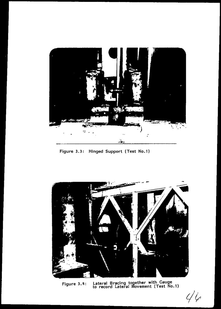
39.
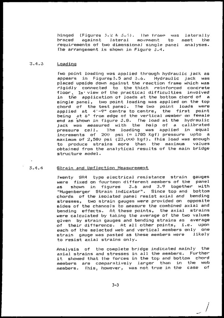
hinged (Figures ^-2 & &.-'>) . I he -I raw? was laterallybraced
against
lateral
movp/nent
to
meet
the
requirements of two dimensions] single? panel analyses.
The arrangement is shown in Figure 6.'\.
Loading
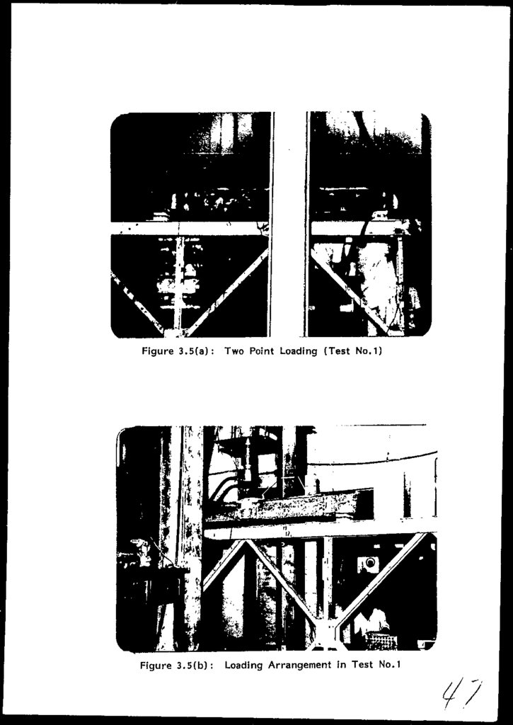
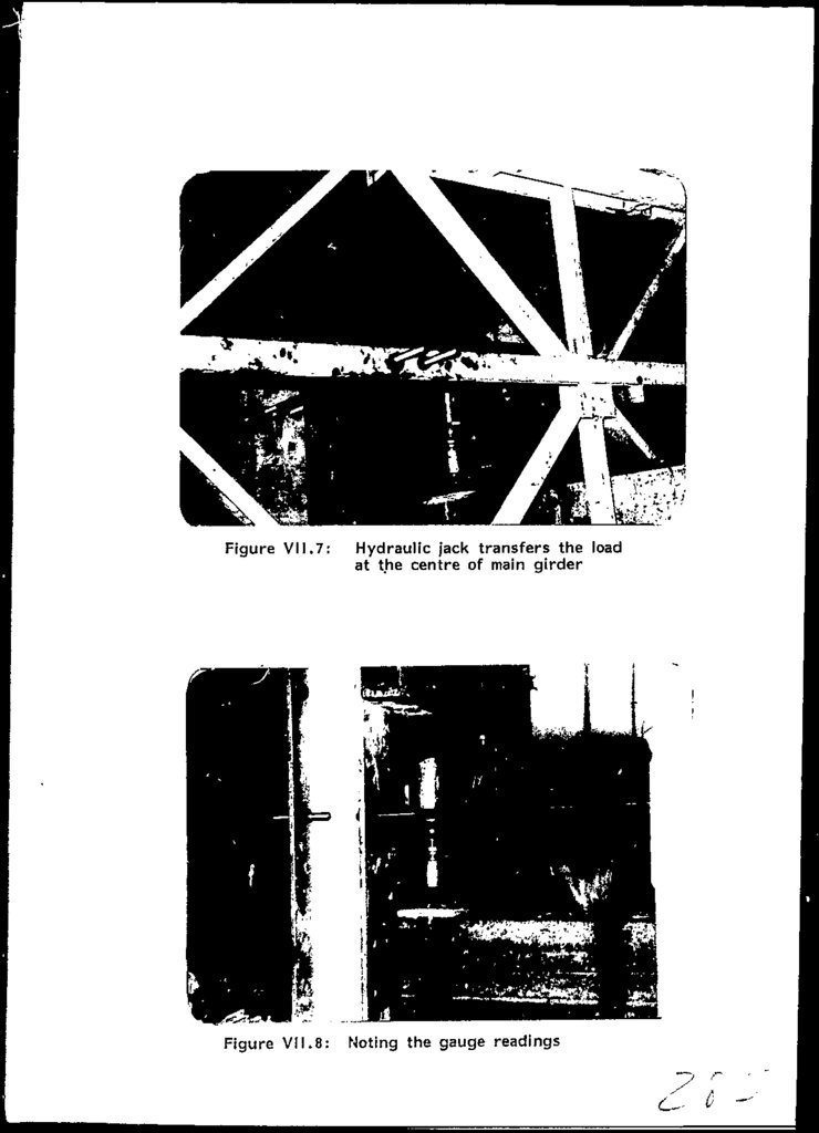
Two point loading was applied through hydraulic jack as
appears in Figures•?.5 and 3.6.
Hydraulic jack was
placed upside down against the reaction frame which was
rigidly connected to the thick reinforced
concrete
floor. In' view of the practical difficulties involved
in the application of loads at the bottom chord of a
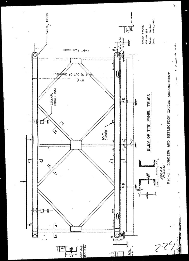
single panel, two point loading was applied on the top
chord of the test panel. The two point loads were
applied at 4'-9" centre to centre, the first point
being at 6" from edge of the vertical member on female
end as shown in figure 3.8.
The load at the hydraulic
jack was measured with the help of a calibrated
pressure ceJ1.
The loading was applied in equal
increments of 200 psi (« .1785 Kgf) pressure upto a
maximum of 2,5SO psi (23,OOO kgf). This load was enough
to produce strains more than the maximum
values
obtained from the analytical results of the main bridge
structure model.
3.4.4
S train and Def 1 ec tion Lleasuremen t.
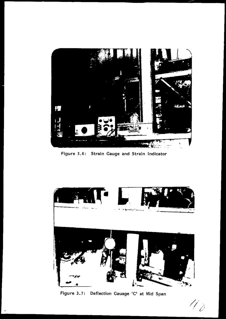
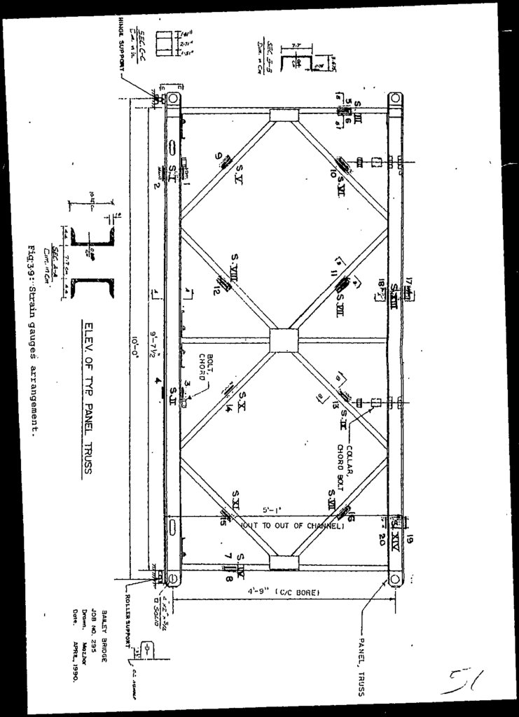
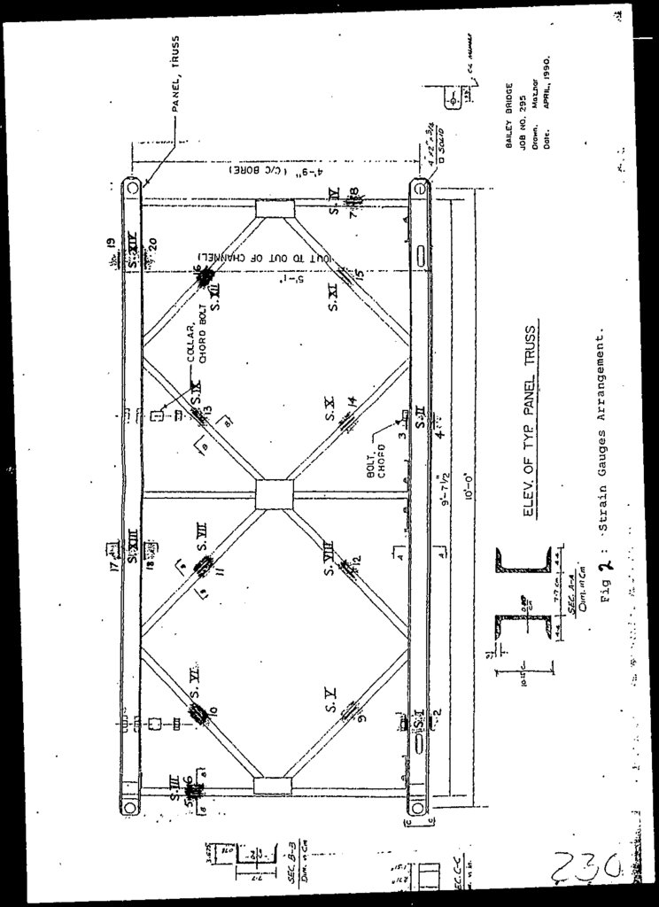
Twenty SR4 type electrical resistance strain gauges
were fixed on fourteen different members of the panel
as
shown in figures
3.6 and 3.9 together with
"Hugenberger Strain Indicator". Since top and bottom
chords of the isolated panel resist axial arid bending
stresses, two strain gauges were provided on opposite
sides of the channels to measure the combined axial and
bending effects. At these points, the axial strains
were calculated by taking the average of the two values
given by strain gauges and bonding strains as average
of their difference. At all either points, i.e. upon
each of the selected web and vertical members only one
strain gauge was pasted as these members were
likely
to resist axial strains only.
Analysis of trie complete brjdge indicated mainly the
axial strains and stresses in all the members. Further
it showed that the forces in the top and bottom chord
members are comparatively larger than in the wota
members.
This, however, was not true in the case of
3-3
40.
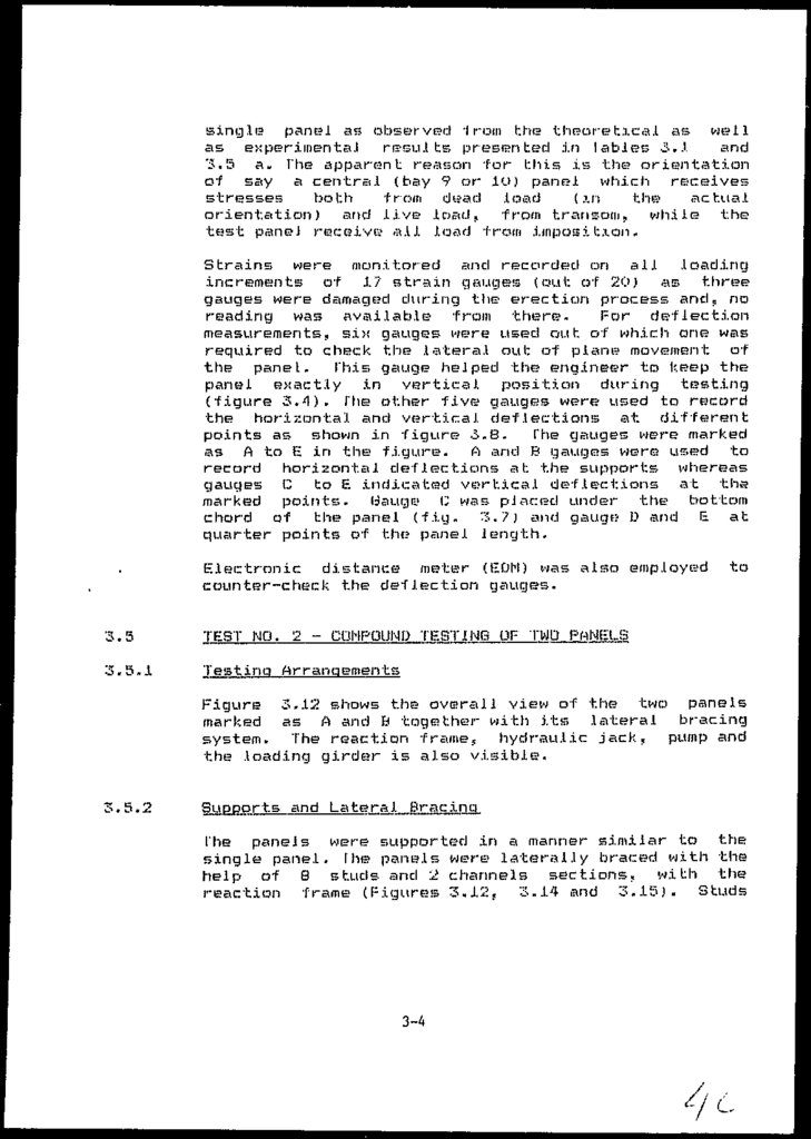
single panel as observed 1 rom the theoretical as wellas experimental results presented in tables 3.J.
and
3.5 a- The apparent reason -for this is the? orientation
of say a central (bay 9 or !(.)) panel which receives
stresses
both
from dead load
(in
the
actual
orientation) and live load, from transom, while the
test paneJ receive all load from imposition.
Strains were monitored and recorded on all loading
increments of 17 strain gauges (out of 20) as three
gauges were damaged during the erection process and, no
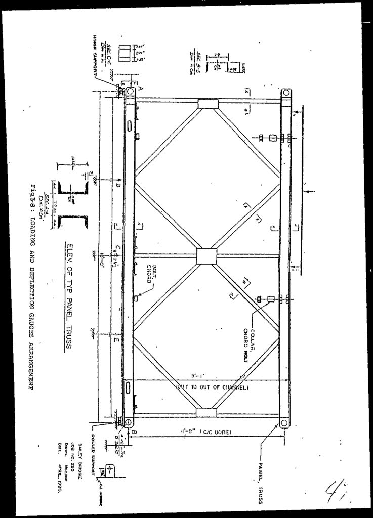
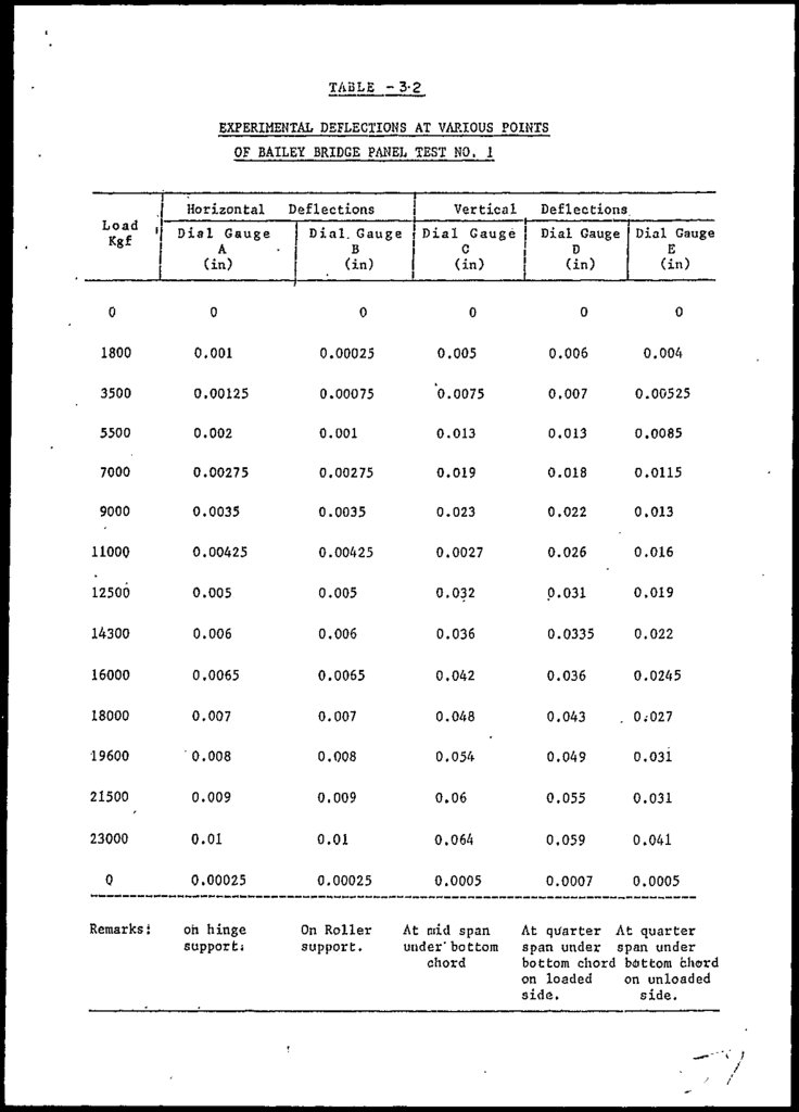
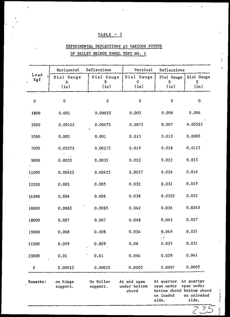
reading was available from thereFor deflection
measurements, six gauges were used out of which one was
required to check the lateral out of plane movement of
the panel. This gauge helped the engineer to keep the
panel exactly in vertical position during testing
(figure 3.4). The other five gauges were used to record
the horizontal and vertical deflections at different
points as shown in figure 5.8. The gauges were marked
as A to E in the figure. A and B gauges were used to
record horizontal clef lections at the supports whereas
gauges C to EL indicated vertical deflections at the
marked points. Uaugo! C was placed under the bottom
chord of the panel (f.iy. 3,7) and gauge D and E at
quarter points of the? panel length.
Electronic distance meter (EON) was also employed
counter—check the deflection gauges.
3.5
TEST NO. 2 - COMPOUND TESTING OF TWO PANELS
3.5.1
Testing Arrangements
to
Figure 3.12 shows the overall view of the two panels
marked as A and B together with its lateral bracing
system. The reaction frame, hydraulic jack, pump and
the loading girder is also visible.
3.5.2
Supports and Lateral Bracing
The panels were supported in a manner similar to the
single panel. Fhe panels were laterally braced with the
help of 8 studs and 2 channels sections, with the
reaction frame (Figures 3.1.2, 3.14 and 3.15). Studs
3-4
41.
were -fastened on one? i?nd with the reaction fra/ne and onthe other with the channel sections outside of the
panels with double nuts. Hence,, restraining out of
plane movement,
to meet the requirements of two
dimensional analysis.
3.5.3
Loading Process and Panel Behaviour
In view of the? practical difficulties involved in the
application of loads at the bottom chord of a single
panel,, it was decided to test the remaining two panels
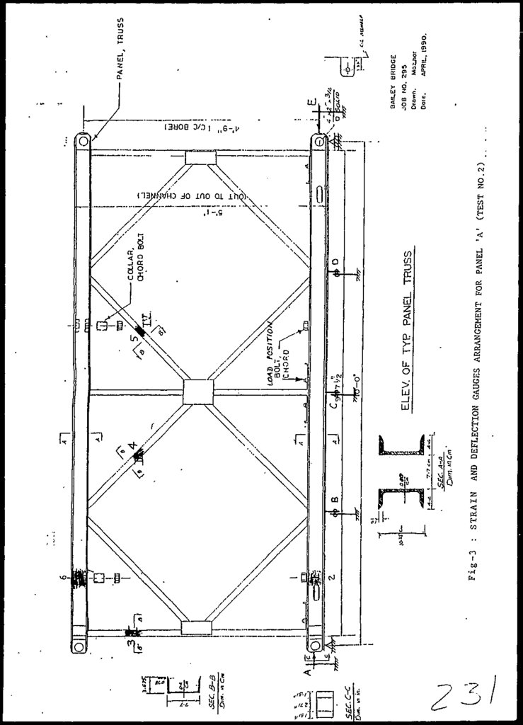
in compound form. It follows that the single point
.loading was possible to be applied simultaneously on
bottom chords of the two panels, 6" from the mid span
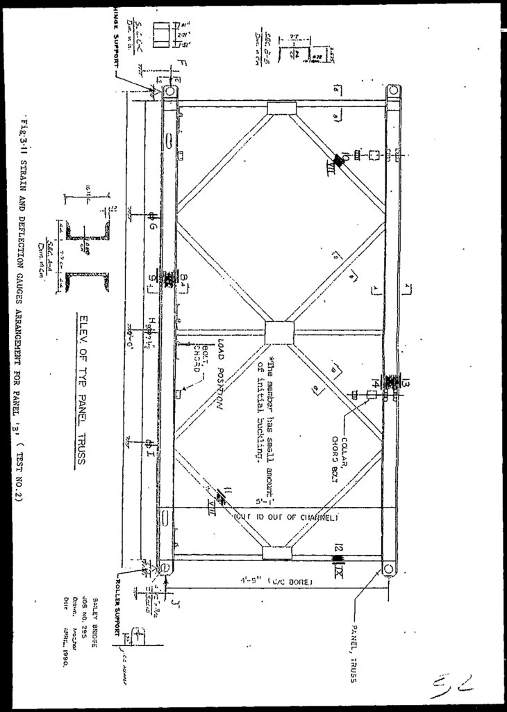
(Figures 3.10 and 3.11). This loading pattern also gave
a closer simulation to actual loading conditions of the
panel in the bridge.
Figures 3..12, 3..13 a and b shows that the hydraulic
jack load was transfered to a rigid girder, which was
simply supported on the bottom chord of each panel (A &
B) at centre to centre span of 5' -6",. The reactions of
the girder were the single point loading on each
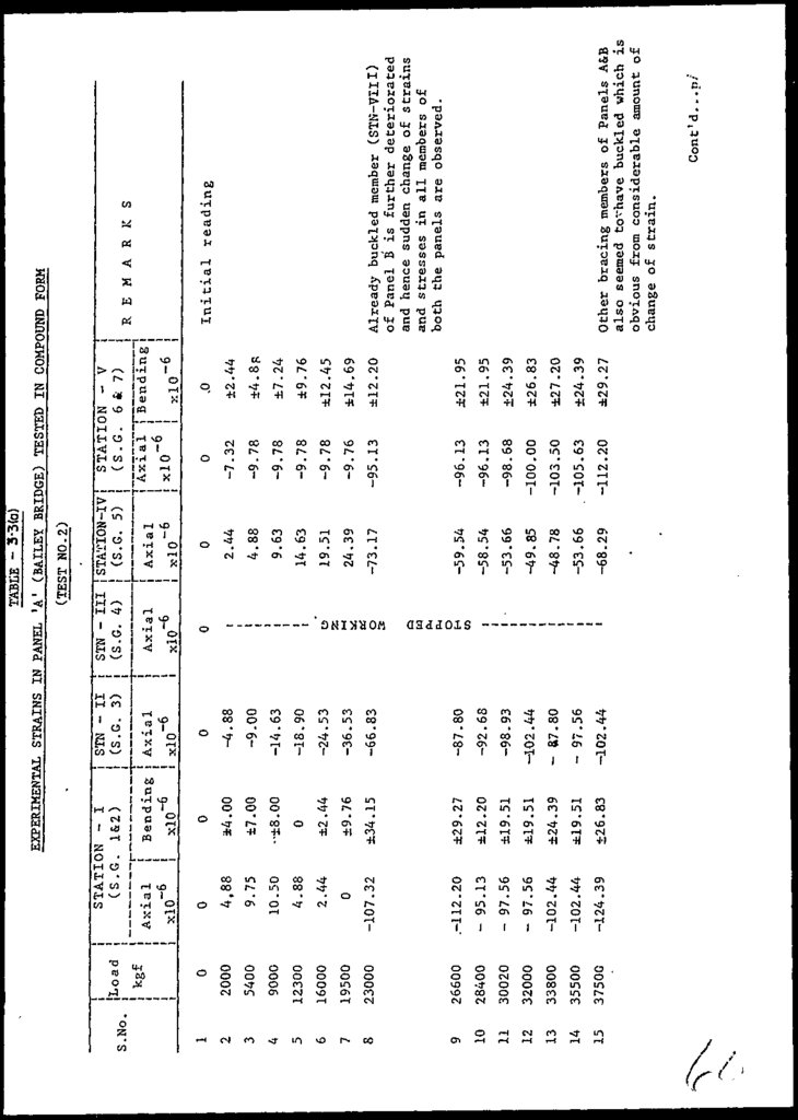
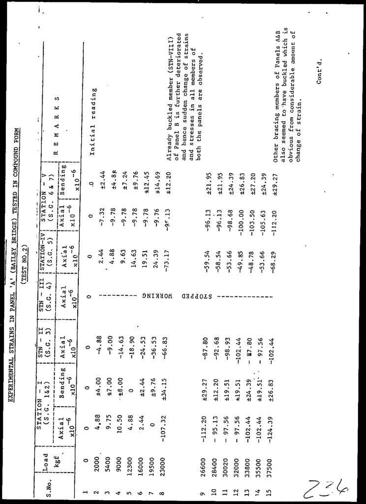
panel. The loading was applied in the increments of 400
psi, i.e. 2OO psi on each of the panels, upto 3200 psi
(26,600 kgf). At this load, initially buckled bracing
member (shown in Figure 3.11) indicated marked increase
in buckling. The study of Tables 3.4 a and 3.4 b
reveals that almost all the members of the panels had
gone through excessive strains and stresses just at or
before this load. Consequently, the onward loading
increments were decreased
to 1OO psi. The panels
stopped resisting further strains at a total pressure
of 4750 psi (40,500 kgf).
3.5.4
Strain and Deflection Measurement.
Strains and deflections were measured and determined as
explained in 3.4.4. In this test, EA type electrical
strain gauges were used instead of SR4 ones. The former
gauges are more sensitive and accurate than the latter
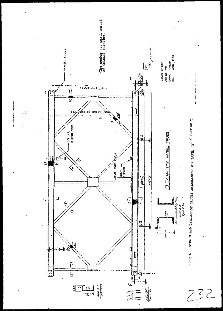
ones. Seven gauges were fixed on five different members
of each of the two panels. The gauges were installed in
such a way that strains at almost all the .important
points were recorded. Figures 3.J.O and 3.11 shows the
arrangmeent of strain arid deflection gauges of panels A
and B, respectively.
3-5
42.
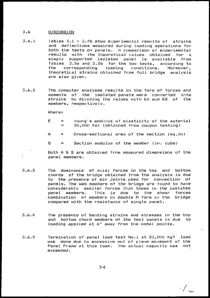
3.6DISCUSSION
3.6.1
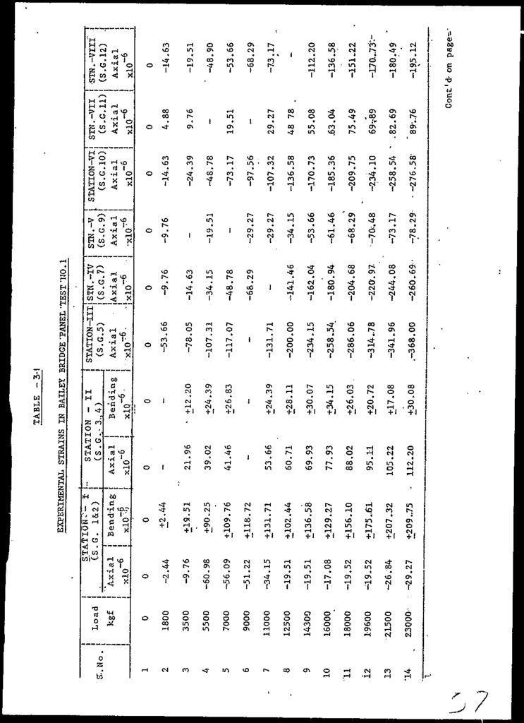
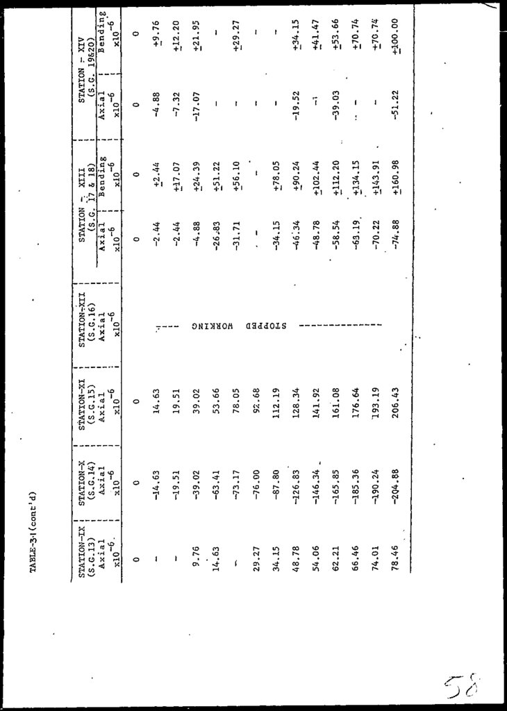
lables 3..I - 3.4b show experimental results of strains
arid deflections measured during .loading operations for
both the tests on panels. A comparison o-f experimental
results with the theoretical values obtained for a
simply supported isolated pane] is available from
Tables 3.5a and 3.5b for the two tests, according to
the
corresponding
loading
conditions.
Moreover,
theoretic.al strains obtained from full bridge analysis
are also given.
3.6.2
The computer analyses results in the form of forces and
moments of the isolated panels were converted into
strains by dividing the values with EO and ES of the
members, respectively.
Where:
E
=
~
Young's modulus of elasticity of the material
30,OOO Ksi (obtained from coupon testing)
A
=
Cross-sectional area of the section
S
=
Section modulus of the member (in. cube)
(sq.in)
Both A ft S are obtained from measured dimensions of the
panel members.
3.6.3
The dominance df axial forces in the top and bottom
chords of the bridge obtained from the analysis is due
to the presence of pin joints used for connection of
panels. "The web members of the bridge are found to have
considerably smaller forces than those in the isolated
panel members.
'[his is due to the shear forces
combination of members in double H form in the bridge
compared with the resistance of single? panel.
3.6.4
The presence of bending strains and stresses in the top
and bottom chord members of the test panels is due to
loading applied at 6" away from the nodaJ points.
3.6.5
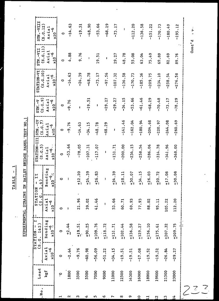
Termination of panel load test No.l at 23,000 Kgf load
was done due to excessive out of plane movement of the
Panel Frame at this load. "I he actual capacity was not
exceeded.
3-6
43.
3.6.6The applied loading gave r.is,e to considerably larger
strains in some of the panel members,, than is likely to
be produced in the panel members of the structure
(Tables 3.5a and 5b)
3.6.7
Loading pattern in lest No. 2 simulates the actual
loading conditions in a closer manner (than lest No.I).
3.6.8
Members of panels A & B (lest Wo.2) showed signs of
abrupt changes and reclistrj.buh.ion of strains at a total
load of only 19,500 Kgf i.e. 9750 Kgf for one panel
(Tables 3.3a and b and 3.5b). This is not true in case
of single panel testing (lest No.I). The behaviour of
the isolated panel was well within elastic: limit even
upto a load of 23,UOU Ky f (Tables 3.1-2 and 3.5a). It
•follows that one of the two point loads i.e. 11,500 Kgf
was transfered about directly to the supports
through
vertical members of the panel (Figure 3.8).
3.6.9
The experimental and theoretical strains generally
did not show agreement with each other for the case of
compound panel test as against a reasonable agreement
for the single panel test (Table 3.5s and 3.5b).
3.6,10
The application of bottom chord single point, loading in
case
of compound panel testing not only
caused
relatively greater bending but also aggravated the
behaviour due to bottom chord loadings local effects.
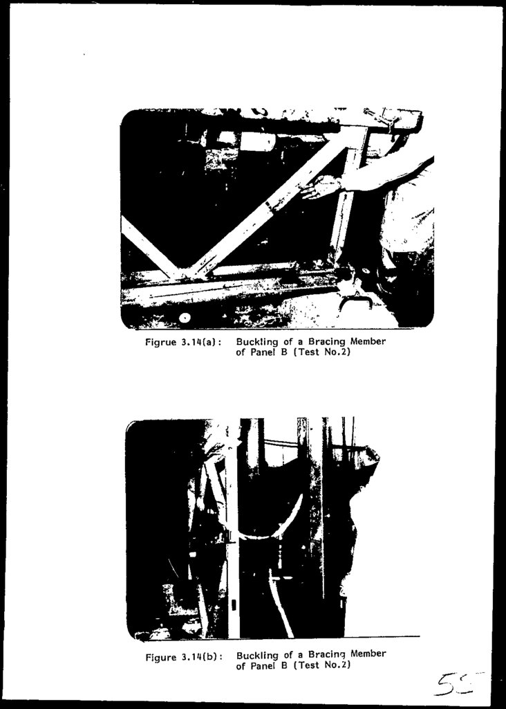
3.6.11
Figures 3.14a and b show the buckling of a bracing
member of panel B. The deflected shape of the compound
panel system is evident from Figures 3.15
and
3.16.
Figure 3.16 also displays vertical buckled member of
panel A together wath rotated hinge support.
3.6.12
Marked buckling of the above mentioned members in 'lest
No.2 contributed towards the failure of compound panel
system.
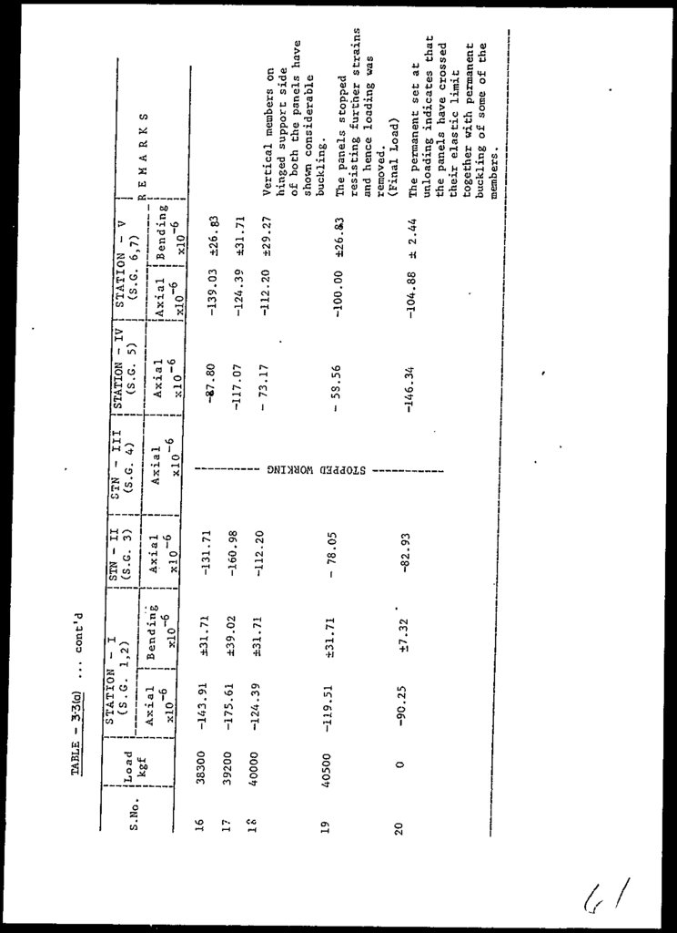
3.6.13
It
is obvious from the permanent set of
nodal
deflections and member strains observed after complete
unloading from the two panels that the panels had gone?
beyond their elastic limits (Tables 3«3a - 3.4b).
3-7
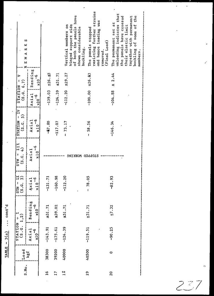
44.
3.6.14The compound panel system slopped resisting furtherloading at 40,500 Kgf indicating failure. However, the
failure was initiated at a load of 19,5000 Kg-f (Tables
3.3a and 3.3b) in probably panel B.Further,
the
behaviour was not linear elastic, since the' early
stages of loading.
3.6.15
As the panels o-f two (double) trusses on each side of
the actual Bridge structure are firmly held by the
panel Braces and turn buckles and transoms under the
wooden deck, considerable third dimension rigidity is
imparted to the actual structure. The individual panels
are held in position and restrained in X-Y plane. Hence
as explained in Section 7.2.3, the failure of panels at
a load of about 20 7 in the compound panel test - Test
No. 2, probably, is not a serious cause of alarm.
3-8
45.
Figure 3.1:Overall view of the Panel
Load Testing Arrangements
(Test No.1)
Figure 3.2: Roller Support (Test No.1)
46.
Figure 3.3:Figure
3.4:
y
Hinged Support (Test No.1)
Lateral Bracing together with Gauge
to record Lateral Movement (Test No.1)
47.
Figure 3 . 5 ( a ) :Two Point Loading {Test No.1)
Figure 3.5(b):
Loading Arrangement in Test No.1
48.
Figure 3.6: Strain Gauge and Strain Indicatorn
•*
Figure 3.7: Deflection Gauage 'C' at Mid Span
I'
49.
HtMCC'3-9.3
ELEV. OF TYP PANEL TRUSS
AND DEFLECTION GAUGES ARRANGEMENT
PANE1-, TRUSS
BAILEY BRIDGE
fiPRIU.
I?SO.
JOB NO. 295
Drawn.
Mouwr
Dole.
50.
£.^. •« in.I HINGE. SUPPORT
Fig-3-9:"Strain gauges arrangement.
"N
TRUSS
51.
MNGESUPPORT
I
~*J
I .4^.
?-7 Cm ,
«**&
ELEV. OF TYP PANEL TRUSS
PA.-JEL, TRUSS
oOlr NO. 235
Drown.
Mciflor
Dois.
tPSiL, I9SO.
52.
POSJST7OA/COLLAR,
™u n G *i BOLT
oo* T
CHORD
\
\\
\\
-2>
,N ''The member has small amountof initial bucklina.
LOAD
TEST NO
ELEV. OF TYP PANEL TRUSS
•Fig.-3-ll STRAIN AND DEFLECTION GAUGES ARRANGEMENT FOR PANEL '3' (
PANEL, TRUSS
SSIDCH
JOB NO. 223
D;own.
Ooie
t-"Rj^. |99O.
53.
Figure 3.12:Overall view of the two Panels
tested in Compund Form (Test No.2)
54.
Figure 3.13(a):Loading Arrangement
note the reading on
pressure gauage
(Test No.2)
Figure 3.13(b) :
Single Point Loading
on each Panel centre
(Test No.2). Note the
deflection in the bottom
chord
55.
(Z'ON isaj.) abupejg E jo Bujivjong
:(q)til'E
g
Bupeug e jo
56.
Figure 3.15: Deflected Panel B (Test No.2)Figure 3.16:
Buckled Vertical
Member & Rotated
Hinged Support
of Penal A
(Test No.2)
57.
\)-17.08
-19.52
3500
5500
7000
9000
11000
12500
14300
16000
18000
19600
21500
23000-
3
4
5
6
7
8
9
10
"11
12
13
•14
_
-29.27
-26.84
-19.52
-19.51
-19.51
-34.15
-51.22
-56.09
-60.98
-9.76
-2.44
1800
2
0
xlO~
6
Axial
0
kgf
+209 ..75
+207.32
+175 ..61
+156.10
+129.27
+136.58
+102.44
+131.71
+118.72
+109.76
+90.25
+19.51
+2.44
0
j Bend'ing
112.20
105.22
95.11
88.02
77.93
69.93
60.71
53.66
-
41.46
39.02
+30.08
+17.08
+20.72
+26.03 ,
+34.15
+30.07
+28.11
+24.39
-
+26.83
+24.39
• +12.20
-
-
21.96
0
xlQ"6
0
xlO~6
STATION - II
( S . G . . 3.,4)
Axial
Bending
.-368.00
-341.96
-3 14 ..78
-286.06
-258.54
-234.15
-200.00
-131.71
-
-117.07
-107.31
-78.05
-53.66
0
-260.69-
-244.08
-220.97
-204.68
-180.94
-162.04
-141.46
-
-68.29
-48.78
-34.15
-14.63
-9.76
0
" }xlO '
STATION-I IIJSTN.-IV
(S.G. 5)
j(S.G.7)
Axial
JAxial
EXPERIMENTAL STRAINS IN BAILEY BRIDGE 'PANEL 'TEST 'NO. 1
STATION-'- I
( S . G . 1&2)
1
S.No
Load
TABLE -3-1
-78.29
-73.17
-70--. 48
-68.29
-61.46
-53.66
-34.15
-29.27
-29.27
-
-19.51
-
-9.76
0
•xlOT6 1
69-/89
75.49
J63.04
55.08
48 78
29.27
-
19.51
-
9.76
4.88
0
x!0"6
-276.58-
'89V.76
-195.12
-180.49
-170...73V
-151.22
-136.58
-112.20
-
-73.17
-68.29
-53.66
-48.90
-19.51
-14.63
0
xlO~6
STN.-VIlf
(S.G. 12) .
Axial
Cont'd- on
STN . -VII
(S.G. 11)
Axial
-258.54 ' .82.69
-234.10
-209.75
-185.36
-170.73
-136.58
-107.32
-97.56
-73.17
-48.78
-24.39
-14.63
0
xlO~ 6
STN.-V [ STATION-VI
(S.G.9)j
(S.G. 10)
Axial i
Axial
58.
•""J••fcj
0
•P-
JL
&
.£
^3
t~*
00
•£*
&\
O
VO
CT*
O>
Ul
C*
M
tO
4>
-P*
to
o">
>
1
0>
co
j_j
vo
on
i>
w
CO
O»
to
*
oo
oo
00
Ul
-P»
00
u>
-P-
to
VO
1
»—
-T-
VO
<-0
*-
^
f-.
O
O
1
O1
-P»
Ul CT>
CO
U)
00
Ul
LO
~-J
^ W
Co >»3
P* • !>
x OH
H-
H
Oi
5^5?
K
^
1
1
)
1
(
1
1
t O C O - i l - i l C T l C J ^ H '
O ^ ^ J C T i C J C O V O V O - P *
O O O O O > - ' - P ' O U l O > >
L O O O ~ J t - 4 t O » - ' ( j i )
CO
^> H
X .
f>> CO f^
o
on
ck P' ^ 1
^x
1
W
0
VO
1
O
00
Cfv
•P-
I— .
O~>
M
VO
to
t O ( - ' V O
O O t O N J
^j
4
>
O
v
- J U l L O t - ' » - '
O 3 W v O v O . p -
Q\
}v4
v
C
O
^5
V
O^
J
i
o
C3
\
t
o
i
'^i
—>
c
M
M' 0 H
i p, i-< z
O^
o
"^
.
W
J^ ^*» Hj
aJ.Urrc.JJ
-*
WUKNIWO
X
•"
£ CO >
* *"3
oI u
IT'
oH
P) . O
o> M H- a
SiH
to
to
oo
oo
-il
0
•«?
i
i
«i4
|
CO
vo
|
CO
-P-
1
00
OS
1
1
,
w
1
1
f - j £ T > 4 > t O I O O
O ^ 4 >
Co
4S
CO
^
t->
Ul
to
|
CO
CO
-vl
1—
|
00
00
1+ " 1+
•£
W
4;-
O>
O
1+
t-1
to
1+
O
to
to
4>
to
o
3
'
4>
*
-
1+
>-4
00
14'vo
O
,L
A
VO
Ut
W
^t
O
1+
Ul
O"v
O
Ul
1+
to
4>
!•(
Ui
(—
M
to
!-
O
,
1+
t^**J
W
vo
vj
|
x
>
0
h-4
1
<y> (U
'
w
H
/^ >
M Co H
bo
^z
— ——-
W -J"
m
X
t-4
O
|+
to
O
«-J
*
J>
10
g »• X
«
H
O- t-- H
l v^* oo w
crv J3 ^-^
OQ
i i^
z ' • • ' b L! s °
(0
o f H:
*
*
-P4>
"
1+
o**
t-"
ui
VO
H*
VO
00
:
A
»-
to
to
t
H1 (U
O
>
X
W
00
O H
. O
z
*
1+
'-j
b
*-4
O
0
O
O
1+
1+
1+
-PM
4*
1+
'o>
1+
to
4>
<
HJ
{jl
|
1+
to
vO
.
10
^4
|
1+
(-
t-1
.
vo
Ul
|
VO '1
«?»
W to X
1+
IO
.
to
O
VO
.
vj
OV
£ 5 S<
O
°*5'
"CO
m— ^^m
59.
TABLE -3-2EXPERIMENTAL DEFLECTIONS AT VARIOUS POINTS
OF BAILEY BRIDGE PANEL TEST NO. 1
Load
Kgf
,
Horizontal
Dial Gauge
A
(in)
Deflections
Dial, Gauge
B
(in)
Vertical
Dial Gauge
C
(in)
Deflections.
Dial Gauge Dial Gauge
E
D
(in)
(in)
0
0
0
0.00025
0.005
0.006
0.004
0.00125
0.00075
'0.0075
0.007
0.00525
5500
0.002
0.001
0.013
0.013
0.0085
7000
0.00275
0.00275
0.019
0.018
0.0115
9000
0.0035
0.0035
0.023
0.022
0.013
11000
0.00425
0.00425
0.0027
0.026
0.016
12500
0.005
0.005
0.032
0.031
0.019
14300
0.006
0.006
0.036
0.0335
0.022
16000
0.0065
0.0065
0.042
0.036
0.0245
18000
0.007
0.007
0.048
0.043
0.-027
19600
0.008
0.008
0.054
0.049
o.osi
21500
0.009
0.009
0.06
0.055
0.031
23000
0.01
0.01
0.064
0.059
0.041
0.00025
0.00025
0.0005
0.0007
0.0005
oh hinge
support*
On Roller
support.
0
0
1800
0.001
3500
0
Remarks :
0
At mid span
under' bottom
chord
At quarter At quarter
span under span under
bottom chord bottom chord
on loaded
on unloaded
side.
side.
60.
02000
5400
9000
12300
16000
19500
23000
26600
28400
30020
32000
33800
35500
3750G
2
3
4
5
6
7
8
9
10
11
12
13
14
15
kgf
1
S.No.
Load
-124.39
-102.44
-102.44
- 97.56
- 97.56
- 95.13
.-112.20
-107.32
0
2.44
4.88
10.50
9.75
4,88
0
xlCf
6
Axial
I
±26.83
±19.51
±24.39
±19.51
±19.51
±12.20
±29.27
±34.15
±9.76
±2.44
0
-±8.00
±7.00
±4.00
0
xl(f
6
! Betiding
STATION - I
( S . G . 1&2)
-102.44
- 97.56
- 87.80
-102.44
-98.93
-92.68
-87.80
-66.83
-36.53
-24.53
-18.90
-14.63
-9.00
-4.88
0
xio'
Axial
6
STN - II
(S.G. 3)
r
H
CO
O
Q
W
O,
0,
o
S
2
e>'
0
xio"
6
STN - III
(S.G. 4)
. ...
Axial
]
r,
-68.29
-53.66
-48.78
-49.85
-53.66
-58.54
-59.54
-73.17
24-39
19.51
14.63
9.63
4.88
2.44
0
x-10~ 6
Axial
.j--,-!
(S.G. 5)
-98.68
-96.13
-96.13
-95.13
-9.76
-9.78
-9.78
-9.78
-9.78
-7.32
0
-103.50
-112.20
±29.27
±24.39
±27.20
±26.83
±24.39
±21.95
±21.95
±12.20
±14.69
±12.45
±9.76
±7.24
±4.8p
±2.44
.0
Axial i Bending
i ^~6 i
,
xlO
i
, . -6
i
xlO
-100.00
_j
STATION - V
( S . G . 6 ft 7)
. -105.63
STATION-IV
(TEST NO.2)
Cont'd. . .n/
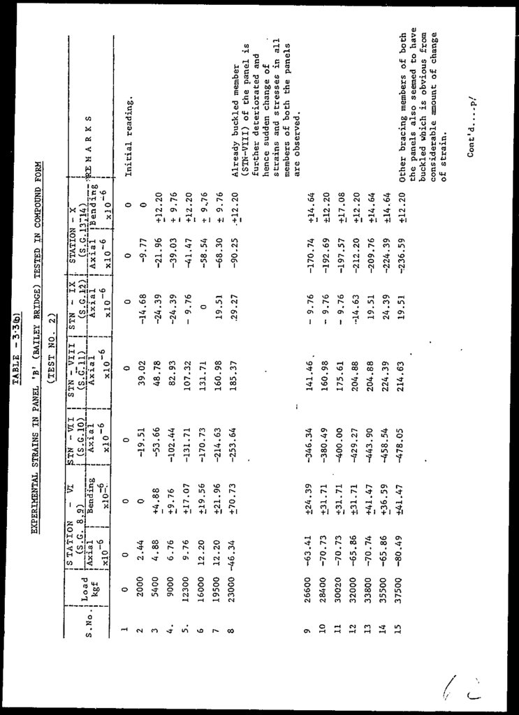
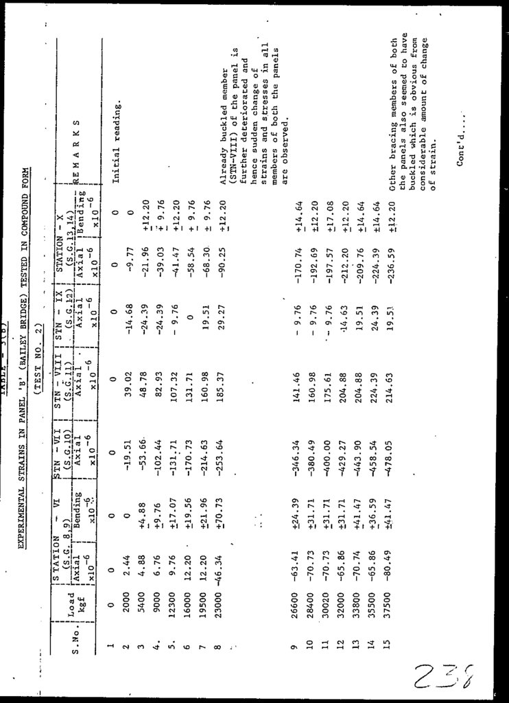
Other bracing members of Panels A&B
also seemed to "have buckled which is
obvious from considerable amount of
change of strain.
Already buckled member (STN-VIII)
of Panel B is further deteriorated
and hence sudden change of strains
and stresses in all members of
both the panels are observed.
Initial reading
R E M A R K S
EXPERIMENTAL STRAINS IN PANEL 'A' (BAILEY BRIDGE) TESTED IN COMPOUND FORM
TABEE ~ 3-3(0)
61.
4000040500
ft
1 e>
19
0
39200
17
20
38300
16
Load
-
-90.25
-119.51
-124.39
-175.61
-143.91
xlO~ 5
Axial
'
(S G
cont'd
!i
STN - II
(S.G. 3)
±7.32
±31.71
±31.71
±39.02
±31.71
xlO~ 5
!
-82.93
- 78.05
-112.20
-160.98
-131.71
xlO~6
,. ~T
Bending { Axial
i.*1
...
STATION
TABLE - 3-3(0)
CO
CM
CM
a
w
3
M
S£
C6
0
o
xlO
Axial
6
STN - in
(S.G. 4)
-146.34
- 58.56
- 73.17
-117.07
-87 . 80
xl
0 ~6
xlO
"—^—————.
Axia
A
x i a]l
I
-104.88
-100.00
-112.20
-124.39
-139.03
IxlO- 6
± 2.44
±26.8,3
±29.27
±31.71
±26.83
| xio'6
_
The permanent set at
unloading indicates that
the panels have crossed
their elastic limit
together with permanent
buckling of some of the
members.
The panels stopped
resisting further strains
and hence loading was
removed.
(Final Load)
Vertical members on
hinged support side
of both the panels have
shown considerable
buckling.
R E M A R K S
-rJAxial ! Bending
' STATION - IV ~1 STATION - V
(S.G. 5)
(S.G.
!
(S.G. 6,7)
62.
f.-5400
9000
12300
16000
19500
23000 -46.34
26600
28400
30020
32000
33800
35500
37500
3
4.
5.
6
7
8
9
10
11
12
13
14
15
-80.49
-65.86
-70.74
-65.86
-70.73
-70.73
-63.41
12.20
12.20
9.76
6.76
4.88
2.44
2000
2
0
IxlO-
6
i
TAxial T
0
kgf
Load
-
VI
±41.47
+36.59
+41.47
+31.71
+31.71
+31.71
±24.39
+70.73
+21.96
+19.56
+17.07
+ 9.76
+4.88
0
0
xlO=*
Bending
( S . G . 8,9)
1
S .No .
!
|S TATION
i
i
-478.05
-458.54
-443.90
-429.27
-400.00
-380.49
-346.34
-253.64
-214.63
-170.73
-131.71
-102.44
-53.66
-19.51
0
xlO-6
Axial
j (S.G. 10)
ISTN -vii
i
i
214.63
224.39
204.88
204.88
175.61
160.98
141.46
185.37
160.98
131.71
107.32
82.93
48.78
39.02
0
19.51
24.39
19.51
-14.63
- 9.76
- 9.76
- 9.76
.29.27
19.51
0
- 9.76
-24.39
-24.39
-14.68
0
t236.59
-224.39
-209.76
-212.20
-197.57
-192.69
-170.74
-90.25
-68.30
-58.54
-41.47
-39.03
-21.96
-9.77
0
+12.20
+14.64
+14.64
+12.20
+17.08
+12.20
+14.64
.+12.20
+ 9.76
+ 9..76
+12.20
+ 9.76
+12.20
0
0
STN - VIII STN - IX , STATION - X
L__ (S.GJ.1) _,
(S.G.12).,t
(S.G. 13214)
Axial
Axial
Axial {"Bending
xlO- 6
xlO-6
xlO~6 i x]0~6
Cont'd
p/
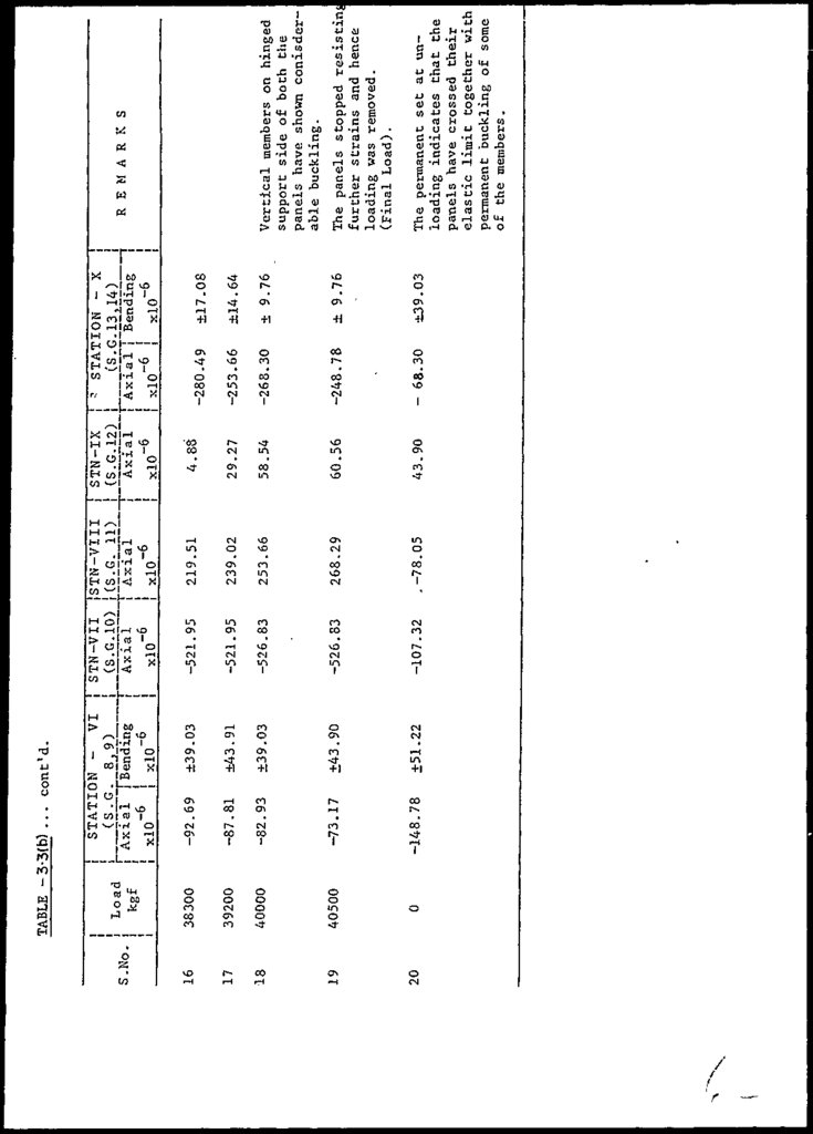
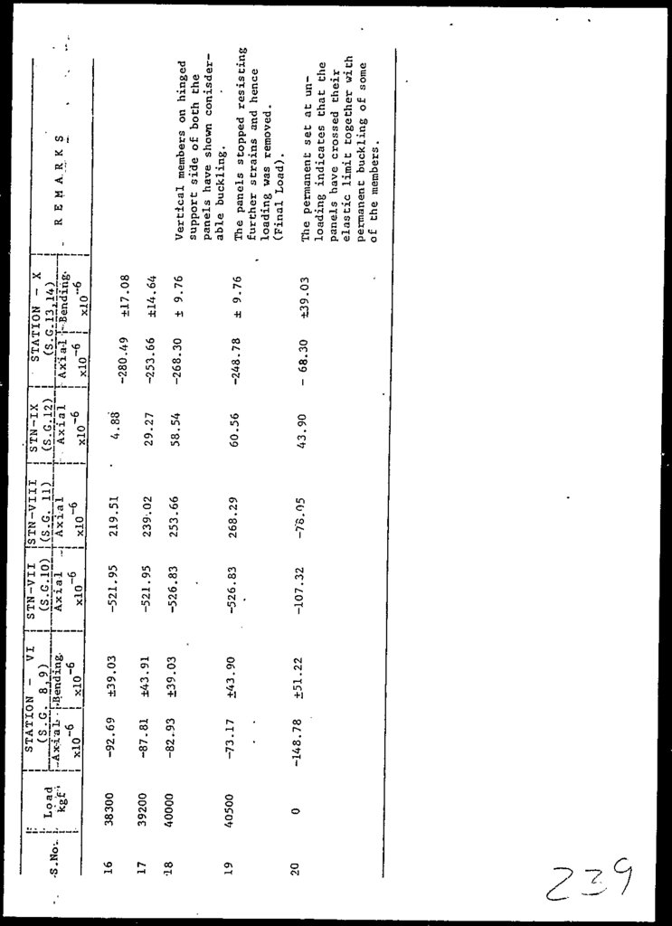
Other bracing members of both
the panels also seemed to have
buckled which is obvious from
considerable amount of change
of strain.
Already buckled member
(STN-VIII) of the panel is
further deteriorated and
hence sudden change of
strains and stresses in all
members of both the panels
are observed.
Initial reading.
!1—
!
L
'i E M A R K S
(BAILEY BRIDGE) TESTED IN COMPOUND FORM
(TEST NO. 2)
EXPERIMENTAL STRAINS IN PANEL 'B'
TABLE -3-3(b)
63.
3830039200
40000
40500
0
17
18
19
20
kgf
16
S.No.
Load
-148.78
-73.17
-82.93
-87.81
-92.69
xlO~ 6
±51.22
±43.90
±39.03
±43.91
±39.03
j xlO~ 6
STATION - VI
( S . G . 8j 9 )
A x i a l j Bending
TABLE -3-3(b) ... cont'd.
r
-107.32
-526.83
-526.83
-521.95
-521.95
xlCf 6
STN-VII
(S.G.10)
Axial
.-78.05
268.29
253.66
239.02
219.51
x!0~6
STN-VIII
(S.G. 11)
Axial
43.90
60.56
58.54
29.27
4.88
xlO~ 6
STN-IX
(S.G. 12)
Axial
- 68.30
-248.78
-268.30
-253.66
-280.49
xlO~ 6 j
±39.03
± 9.76
± 9.76
±14.64
±17.08
xlO~ 6
' STATION - X
(S.G. 13,14)
A x i a l i Bending
The permanent set at unloading indicates that the
panels have crossed their
elastic limit together with
permanent buckling of some
of the members.
Vertical members on hinged
support side of boch the
panels have shown conisderable buckling.
The panels stopped resistinj
further strains and hence
loading was removed.
(Final Load).
R E M A R K S
64.
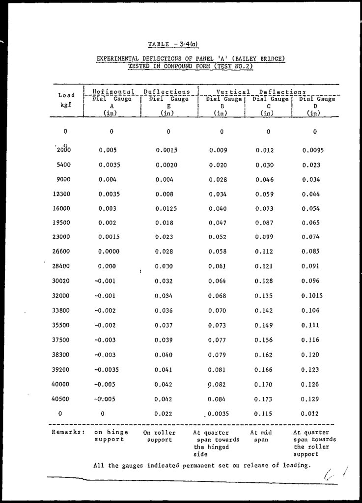
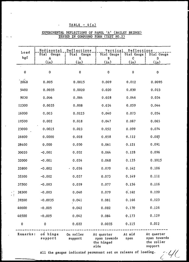
TABLE - 3-4(o)EXPERIMENTAL DEFLECTIOtiS OF PANEL ' A ' (BAILEY BRIDGE)
TESTED IN COMPOUND FORM (TEST NO. 2)
Load
i
H
o
r
i
z
o
n
t
a
l
D
e
f
l
e
c
t
ions
J
Vei t i c a l D e f l e c t ions
jDial Gauge j Dial Gauge j Dial Gauge j Dial Gauge { Dial Gauge
E
D
A
C
!
(in)
!
(in)
!
(in)
!
(in)
!
(in)
0
0
0
0
0
0
'2680
0.005
0.0015
0.009
0.012
0.0095
5400
0.0035
0.0020
0.020
0.030
0.023
9000
0.004
0.004
0.028
0.046
0.034
12300
0.0035
0.008
0.034
0.059
0.044
16000
0.003
0.0125
0.040
0.073
0.054
19500
0.002
0.018
0.047
0.087
0.065
23000
0.0015
0.023
0.052
0.099
0.074
26600
0.0000
0.028
0.058
0.112
0.085
28400
0.000
0.030
0.061
0.121
0.091
30020
-0.001
0.032
0.064
0.128
0.096
32000
-0.001
0.034
0.068
0.135
0.1015
33800
-0.002
0.036
0.070
0.142
0.106
35500
-0 . 002
0.037
0.073
0.149
0.111
37500
-0.003
0.039
0.077
0.156
0.116
38300
-0.003
0.040
0.079
0.162
0.120
39200
-0.0035
0.041
0.081
0.166
0.123
40000
-0.005
0.042
0.082
0.170
0.126
40500
-OV005
0.042
0.084
0.173
0.129
0
0
0.022
.0.0035
0.115
0.012
At quarter
span towards
the hinged
side
At mid
span
Remarks :
on h i n g e
support
On roller
support
At quarter
span towards
the roller
support
All the gauges indicated permanent set on release of loading.
65.
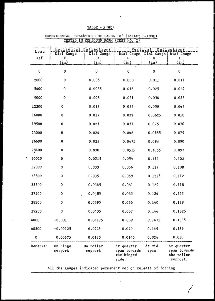
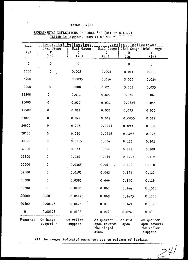
TABLE »3'4(b)EXPERIMENTAL DEFLECTIONS OF PANEL 'B 1 (BAILEY BRIDGE)
TESTED IN COMPOUND FORM (TEST NO. 2)
Horizontal
Dial Gauge
F
(in)
Load
kgf
0
0
2000
0
5400
9000
Deflections
i Dial Gauge
!
J"
I
(in)
0
Vertical
Deflections
Dial Gauge \~fiial Gauge [ D i a l Gauge
G
!
H
!
I
(in)
! (in)
!
(in)
0
0
0
0.005
0.008
0.011
0.011
0
0.0035
0.016
0.025
0.024
0
0.008
0.021
0.038
0.035
12300
0
0.013
0.027
0.050
0.047
16000
0
0.017
0.032
0.0625
0.058
19500
0
0.021
0.037
0.075
0.070
23000
0
0.024
0.042
0.0855
0.079
26600
0
0.028
0.0475
0.09R
0.090
28400
0
0.030
0.0515
0.1055
0.097
30020
0
0.0315
0.054
0.112
0.102
32000
0
0.033
0.056
0.117
0.108
33800
0
0.035
0.059
0.1225
0.112
35500
0
0.0365
0.061
0.129
0.118
37500
0
0.0385
0.063
0.134
0.123
38300
0
0.0395
0.066
0.140
0.129
39200
0
0.0405
0.067
0.144
0.1325
40000
-0.001
0.04175
0.069
0.1475
0.1365
40500
-0.00125
0.0425
0.070
0.149
0.139
0
0.00675
0.0185
0.0145
0.024
0.030
On hinge
support
On roller
support
At quarter
span towards
the hinged
side.
Remarks :
,
At mid
span
At quarter
span towards
the roller
support.
All the gauges indicated permanent set on release of loading.
/
66.
-260.69IV
XIV
XIII
-
-74.88
-
206.43
XI
XII
-204.88
78.46
-195.12
89.76
-276.58
X
IX
VIII
VII
VI
-
-368.00
III
V
112.20
-
Experimental
Strain
(X10~b)
II
I
Member
0.28
-77.22
-340.78
339.45
-223.66
104.08
-198.93
104.21
-365.67
361.99
-474.05
-486.71
98.21
1.13
-177.09
-179.80
-22.43
22.50
-25.33
45.38
-55.63
67.96
32.00
26.97
2.60
-70.86
172.36
180.86
Treoretical Strain ( X10~6)
Single
Complete
Panel
Bridge
analysis© analysis (gg
0.970
-
0.608
0.916
0.752
0.980
0.861
0.756
-
0.550
0.756
1.143
.
/Ratio\
\l/2a/
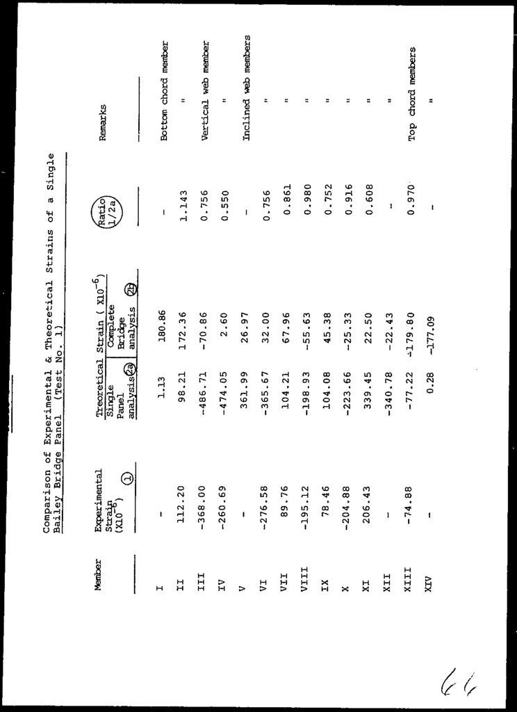
Comparison of Experimental & Theoretical Strains of a Single
Bailey Bridge Panel (Test No. 1)
n
Top chord members
it
»
n
n
»
n
M
Inclined web members
it
Vertical web member
M
Bottom chord member
Remarks
67.
c\19.51
-68.30
X
160.98
VIII
IX
-214.63
12.20
VI
VII
0.00
-9.76
V
-37.60
22.80
256.80
-197.40
27.20
169.20
224.90
-
III
24.39
-16.00
-36.53
II
IV
0.00
(isolated
panel)
Strains (X10~6) at 9750 Kgf
Experimental
Theoretical
0.00
I
Member/
Station
-236.59
19.51
224.39
-478.05
-80.49
-112.20
-68.29
-
-102.44
-124.39
-72.20
43.85
493.85
-379.50
51.80
0.00
325.30
432.40
-30.77
0.00
(isolated
panel)
Strains (X106 ) at 18750 Kgf
Experimental
Theoretical
-173.80
70.80
27.00
-32.00
172. 3Q
-177.10
90.80
203.90
70.80
178.00
Theorjical
Strain
(X10 b ) from
complete Bridge
analysis
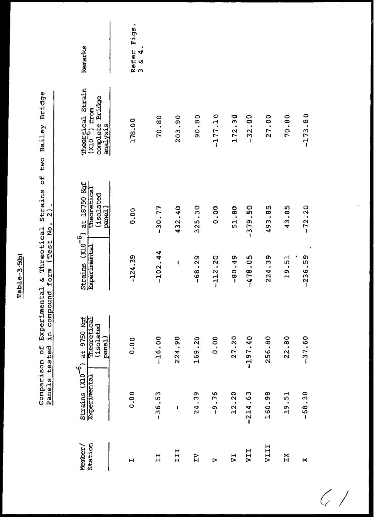
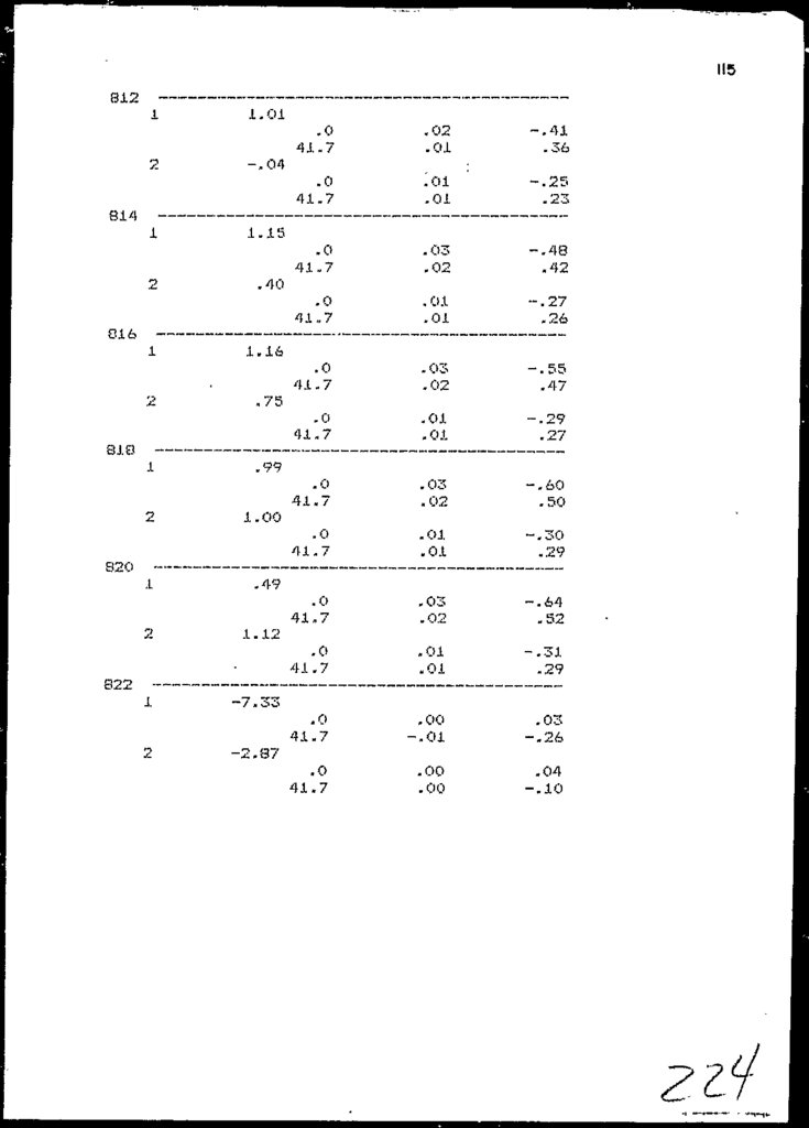
Comparison of Experimental & Threotical Strains of two Bailey Bridge
Panels tested in compound form (Test No. 2).
Table-3-5(b)
Refer Figs.
3 & 4.
Remarks
68.
CHAPTER - 4SITE
VISIT
REPORT
69.
SITE VISIT REPORT4.1
VISIT 10 THE 81 IE
MCE team comprised ot two engineers, the Project
Manager and Chief testing Engineer. I he team visited
the Bailey Bridge site to collect the coupons, conduct
the inspection survey and check the general conditions
of the structure.
Earlier the team held a meeting with the CCSC Chief of
Party in Peshawar office, to acquire GOP Clearance
regarding security and arrangements for collection of
the samples/coupons.
The ACE team conducted the inspection
and supervised
the collection and repair of coupons in the presence of
CCSC/ACLU and SOP representatives. I he team had taken
with them 16 replacement coupons obtained from the
tested panel (test No.l).
4.2
COUPON REMOVAL
The coupon removal and repair was carried out in
accordance with ASJ'M A-6 and A-37O I12J.
The selection
of
the
coupons
was
based
on
the
following
considerations.
-
Panel location w.r.t. moment & shear forces
Accessibility
Member condition
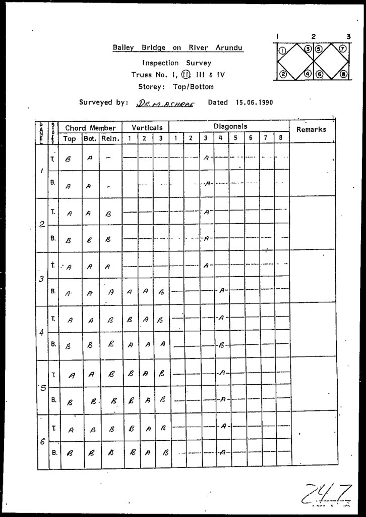
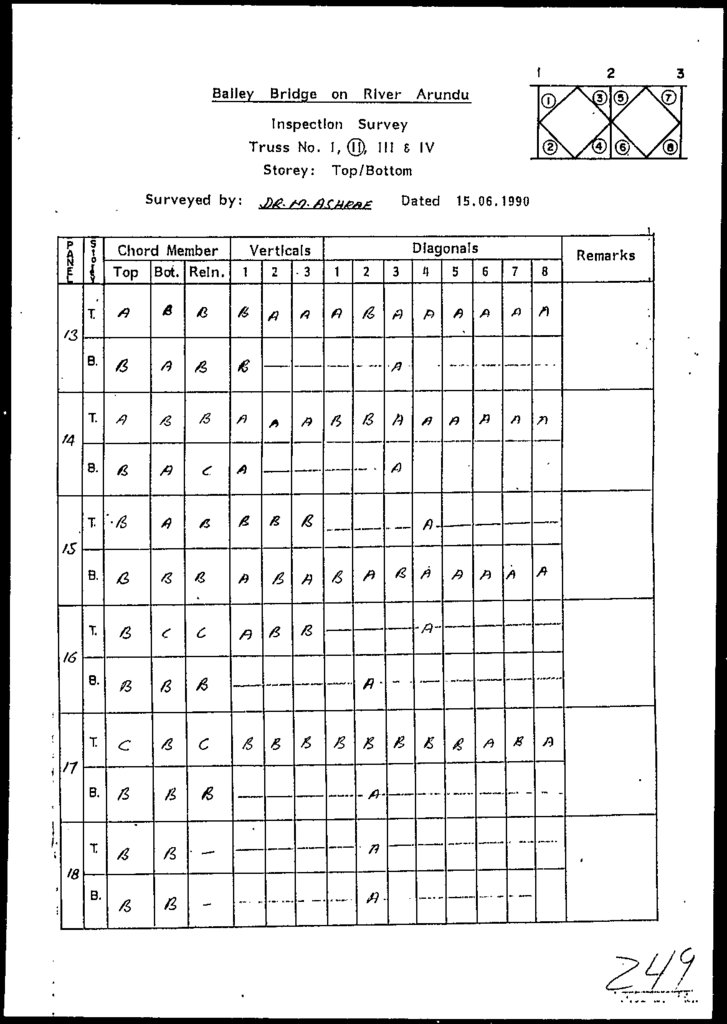
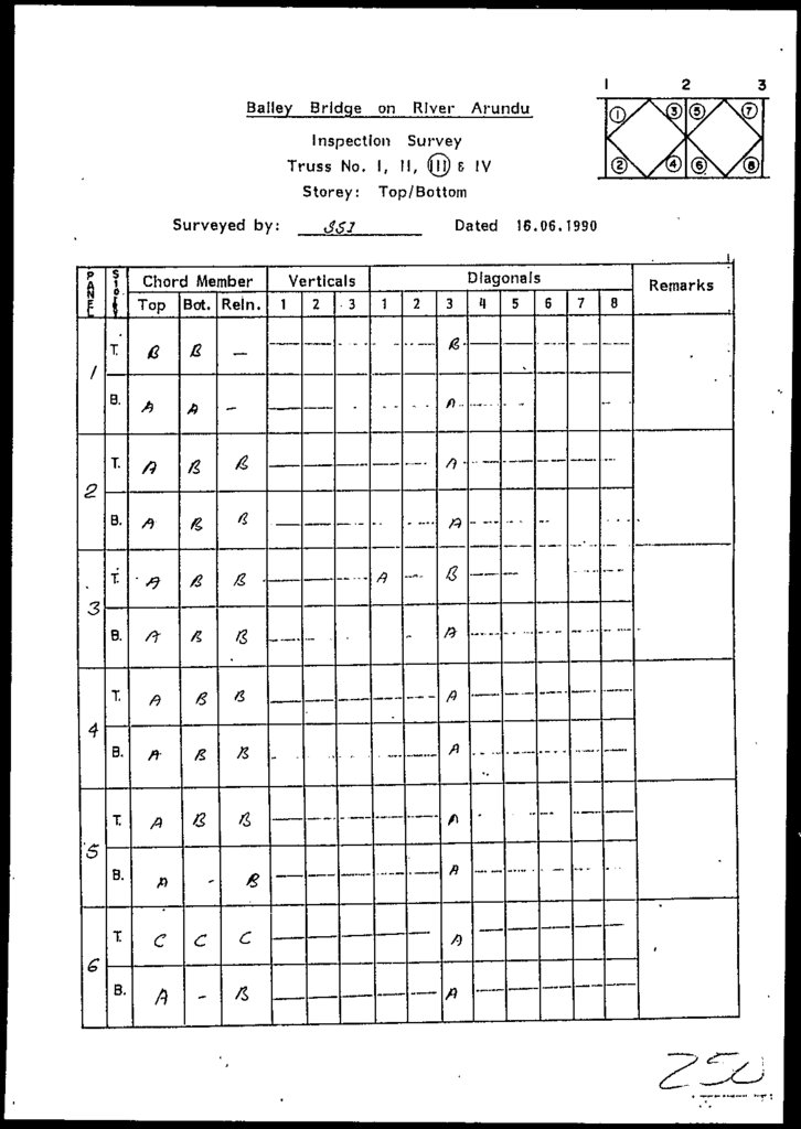
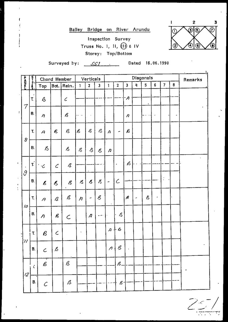
Standing on the left abutment the trusses were numbered
1,11 on left side and 111, IV on right side (ref. fig.
2.2).
Each truss has IB bays. All the bays were
assigned
serial numbers 1 to 18 from left to right
abutment.
Twenty coupons - ten each from chord and bracing
members were collected/extracted from the different
panels of the existing structures mentioned in table
4.1. Based on the tension test requirements the length
of coupon was maintained equal to .18 inches.
4-1
70.
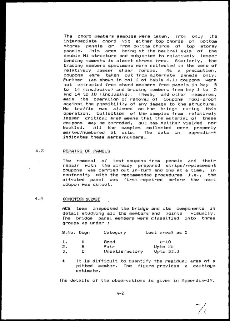
The? chord members samples were; taken, from only theintermediate chord vis either top chords of bottom
storey panels or from bottom chords of top storey
panels. This area being at the neutral a>:.ts of the
double Ml structure and subjected to relatively lesser
bending moments is almost stress free. Similarly, the
bracing members specimens were collected in the zone of
relatively l£?sse?r shear forces.
Pis. a
precaution,
coupons were taken out from alternate panels only.
Further (as shown in col 3 of table 4 . .1) coupons were
not extracted from chord members from panels in bc\y 5
to 14 (.inclusive) and bracing members from bay 1 to 5
and 14 to 18 (inclusive^ , these,, and other measures,
made the operation of removal of coupons fool-proof
against the possibility of any damage; to the structure.
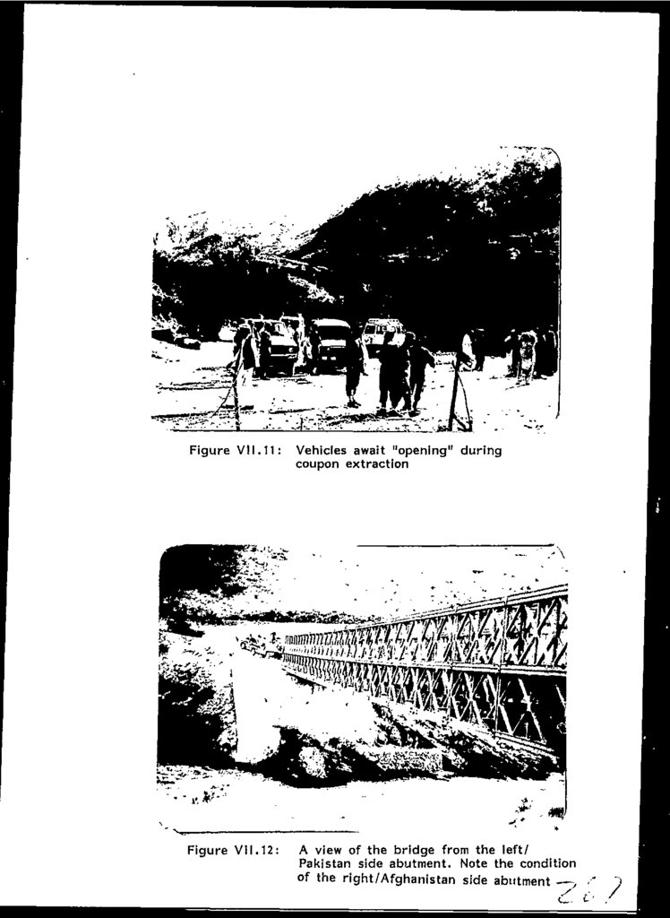
No traffic was allowed on the bridge* during this
operation. Collection of the? samples from relatively
lesjjer critical area means that, the material of these
coupons may be corroded, but has neither yielded nor
buckled.
All the samples collected were properly
marked/numbered at site.
The data in
appendix-V
indicates these marks/numbers.
4.3
REPAIRS OF PANELS
The removal of test coupons from panels and their
repair with the already prepared strips/replacement
coupons was carried out in-turn and one at a time, in
conformity with the recommended procedures i.e., the
affected panel was first repaired before the next,
coupon was cutout.
4.4
CONDITION SURVEY
ACE team inspected the bridge and its components in
detail studying all the members and joints
visually.
The bridge panel members were classified
into three
groups as under :
S.No. Dsgn
1.
2.
3.
*
A
B
C
Category
Good
Fair
Unsatisfac tory
Lost area* as
0-10
Upto 2U
Upto 33.3
It is difficult to quantify the residual area of a
pitted member. The figure provides a cautious
estimate.
The details of the observations is given in Appendix-IV.
4-2
71.
4.5OBSERVATIONS DURlNti 1NSPECI I UN
The following
inspection
important
points
were
rioted
by
the
4.5.1
No component part/member such as panels, truss, transom
raker, sway / other bracing, chord bolts etc: was found
missing.
4.5.2
Generally, transom girders and fasteners were found to
be in good conditions. However, the pins were not
properly oiled as required tor a Bailey Bridge used as
a permanent structure L.IJ-
4.5.3
Some of the cotter pins were not fanned out properly.
4.5.4
The bridge equipment other than various panels seemed
to be unused.
The criterion for this categorization
was based on the condition of transom seat and bolt.
(Ref. Chapter—5).
4.5.5
Almost all the reinforcing chords provided in bays
217 (inclusive) can only be categorized as B or C. One
of the members has a hole through the web (fig. 4.6)
which is attributed to severe corrosion attack. The
surrounding area is also found pitted there.
4.5.6
Chord members of panels were fairly corroded or damaged
(Refer figures 4-1-4,1U). Corrosion is generally severe
around the transom seat area. Figure 4.4 shows damaged
transom seat. I he crack observed .in the? welding between
the transom seat and bottom chord seems to be caused by
Fatigue.
4.5.7
Slight buckling and non alignment of some of the chord
members was also noted which may have resulted
during
handling, or probable previous use. (Refer figs. 4.9
and 4.10).
4.5.8
The bracing members are generally in good conditions.
However, a buckled bracing member shown in fig 4.9
suggests that probably the panels remained in improper
storage (since its manufacture in 1951), or improperly
handled sometimes or, probably put. to structural use.
4.5.9
Some of the panels have chord members marked C. USA and
bracing members (3. USA or John and Bethlehem Carnagie.
This raises doubt whether any original member was
replaceJ.
4-3
72.
4.5.1Uthe condition ot panel in the top storey of bay No. 18
and 9 of truss 111 is probably the worst both these
panels exist at critical locations.
4.5.11
The condition of the reinforcing chords is
unsatisfactory.
4.5.12
Cracks in the welding and/or repairs to the existing
welding noted on some panels - especially at the
transom seat, is considered as an evidence of fatigue
or use of the members previously in a Bridge structure.
4.5.13
The
sag/vertical deflection of the structure was
estimated to be about 3 inches, in the unloaded state
of the structure.
4.5.14
The abutments are in good condition.
4.6
COMMENTS ON OBSERVATIONS
especially
Even with the panels available in the present number
(including those used in the launch nose assembly) and
condition the bridge strength could be improved by
better planning/management viz. best chosen panels,
w.r.t. chord condition, used in bays 5 to 12. In fact
the condition of the two critical Panels (ref. 4.5.10)
alone warrant imposing restrictions on the use of this
structure.
4-4
73.
Figure 4.1:Pitted Top Chord of
the Top Storey Panel
in Bay 18 Truss III
Figure 4.2:
Panel repair by means of "Prepared
Replacement Coupons" in progress. The
corrosion is visible on the web member of
the next panel
74.
Figure 4.3:The Top Chord of a bottom storey panel
indicating reduced thickness of the flange,
note also the corrosion visible around the
pins
Figure H.H:
Pitted Transom seats & corroded surrounding
area at bottom chord of a top storey panel,
all such panels are considered "Used"
75.
Figure 1.5:Another damaged Transom seat of bottom
chord top storey panel. Note the condition
of the bolt head and weld with the chord,
considered an evidence of fatigue
Figure 4.6:
Pit Hole formed due to corrosion in the
top reinforcing & chord, indicated blue mark
76.
Figure 1.7:A view of damaged top chord channels
of a top storey panel
Figure 1.8:
A buckled diagonal bracing member of top
storey panel
77.
Figure 4.9:Buckled and corroded
bottom chord member of
a top storey panel
Figure U.10:
a buckled bottom chord
member of a top storey
panel
78.
CHAPTER - 5CHEMICAL
AND TENSION
TESTING
79.
L.HMP IEHJEMICAL AND_ TENS10J1. TESTING
CHEMICAL TESTING
Chemical testing of the coupon?, was entrusted to the
Metal .Industry Research and Development (..enter (MIRDLJ
Lahore. Four samples - extracted from test panel No.J.
were sent to MIRDL Laborator .IP* on 28th May and other
•four samples brought from the site on JLVth June. The
result of analyses are given in table 5..I and actual
report in Append!x-V.
The chemical testing indicates that the
material
complies with A S J M A 588. However, the year of original
adoption o1 this standard being J968 (refer table 5.2)
the material can be stated to be near to that standard
(refer also Sec. S.'l.i).
5.2
COUPON TEST 11Mb"
•3U coupons were prepared in a workshop at Lahore from
the Single panel tested (test No.i) within elastic
limit. It follows that neither the material of this
panel yielded nor members were buckled. .16 coupons were
used to repair Bridge paneJ members at site while
removing coupons.
The coupons were collected and
repaired .in accordance with the standard practice of
ASTM A-6 and A---37U. fhe selection of coupons was
carried out as explained in Chaptet—4.
Out of the 20 coupons collected, 5 were obtained by the
BOP Representative for their testing. Despite their
best efforts, the Consultants did not receive them
back. Consequently, 29 coupons i.e. J5 from the site
and 14 from tested panel were put to physical and
chemical testing. (Jut of which, 4 specimens were tested
both physically and chemically. Physical testing was
carried out in the Civil Engineering Department, U.E.T.
5-1
80.
TESTINGPhysical testing - besides other tests listed in 5.4
involved hardness and Tension testing ot 25 coupons and
3 pins. 200 Ton Shimadzu Universal Testing Machine,
with
Automatic
Load
versus
extension
testing
facility, was employed for tension test on both coupons
and pins. Six coupons were subjected to detailed
testing including plotting of load extension curves in
order
to determine Modulus of Elasticity of the
material. Due to lesser percentage of carbon in Bridge
steel, all the coupons displayed
marked and well
defined yielding plateau. 3 pins were tested by making
special holding facility arid reducing their diameters
on the same machine as per ASTM A-325 section S-4 of
[6J.
Hardness tents on 1U coupons and 3 pins were performed
on Rockwell hardness testing machine using diamond
penetrator and 150 kg of load in order to confirm the
tension and chemical testing resuls. Results of tension
tests on coupons and pins and of hardness
tests are
provided in Tables 5.3 to 5.6 inclusive. The Hardness
test results are given in Standard Hardness Numbers. H
stands for Hardness Number, R for Rockwell testing
machine and C for type of scale.
One truss panel was weighed at the UET
Laboratories
Lahore. The weight of the panel was about 261.0 Kg =
575 Ibs. No deduction is made for any coating/film of
enamal paint. This is considered to be in agreement
with LI].
5.4
OTHER TESTS
Besides the, tension and hardness tests, some other
tests were also performed-on the material and discussed
below.
5.4.1
Hagnaflux Test
This is a non-destructive type of test which is
performed for the detection of surface cracks. The
(.corroded; sample is prepared by hand-filing operation,
and current is passed through the material and fine
red-oxide powder sprinkled. The cracks of any are then
visible by microscopic examination. Mangnaflux test was
performed on four coupons and none revealed any surface
crack.
5-2
81.
5.4.2Visual examination by the- help of niaiqn.i Fying glass
was
carried out cm Ail the? eight samples sent- to the M1RDC.
This examination has shown "small" pit', ling in all
of
them. Coupon Mo.'x (from <.-, \ t.i-) vr- badly pitted.
5.4.3
Sh^ain cj_Uj3ejia,Lj..orj,
J n the process of sampJe pi epnr a hi on , 3O coupons were
"shaped" in shaping machine.
) he operation shows that
the material is high strength., and of good quality.
5.4.4
Boring operation
3 bores on each of the -(our samples was conducted which
showed that corrosion is limited to surface patting.
5.4.5
Ul traspnic___b__e5_tirig.
This test was planned but could not be performed due to
consideratal e ( corrosion > pi ttxny .
5.5
DISCUSSIONS
The
important points concerning the physical and
chemical testing of the coupons are noted hereunder.
5.5.1
Tension and hardness test results of coupon? indicate
that the steel is generally nearer to ASTM A-572 with
the exception of a couple of samples which are closer
to A-588 steel. host of the? tested samples have yield
and ultimate strength in excess of 55 Ksi and 80 Ksi
respectively, (refer table !5.3) which is the requirement of A 572 steel.. Also the Hardness value is nearer
to A 572 steel, lor most of the coupon.
5.5.2
Chemical testing confirms that the steel conforms to
ASTM A-58f-:i. However, teriBj.cn tests indicates A-572
steel due to strength obtained from present
(reduced)
X-sectional area.
5-3
82.
5,5.3The stt?cJ sliowod well defined and marl:c>d y i e J d plateau
and plastic range. Ihxs xs due to approximately 0..2X
carbon content ot the steel.
5.5.4
1 he steel is low carbon alloy and its high strength i
attributed to presence oT Magnest?, Nickel and Chromium
5.5.5
Overall, the material is o-f genuine quality.
5-4
83.
i'AULii b.lChemical Analysis E<esults
(.Percentage Composition of other Elements)
1
2
Specimen Numbers
4
5
3
6
7
6
0.22
Carbon
U .17
U. 22
U. 22
U. 13
U.16
0.22
0.17
Silicon
0.15
0. 22
0. 10
U. 12
U . 18
0.14
0.17 0.15
Chromium
U .11
0. 11
0. 11
U. 21
Manganese
1 .14
U. 74
1. 16
1. 15
Nickel
0.58
0. 64
0. 91
0. 58
Molybdenum
Traces 0.098 0.075
0.86
1.10
_
1.12
_
1.18
_
Traces -
Sulphur
O.U34
0.026
0.037
0.031
Phosphorous
0.018
0.016
0.016
0.014
Not checked
5-5
0
84.
I ABU- !>.'«;Year of Or.ig.inaJ adoption of the- various relevant
Standards*.
Sr.
No.
AS I'M
Designation
Number
1.
A -- 36
i960
2.
A - 242
1941
3.
A •- 441
1970
4.
A - 572
1966
5.
A - 588
1968
Year of
Original
adoption
ASThl
Remarks
*Re ference C2j
#As mentioned in drawing Mo. 8906U7 High Strength, low
A.liloy Steel ussed in panels, Transoms, Strength, End
posts and ramps correspond to rtSTH A-242, A-44.1, A-572
or A-58Q Grade 50.
5-6
85.
8-
3/II
15
17
-
-
10.
11.
12.
13.
14.
15.
-
6.
9.
19
5.
9/III
18
4.
8.
1.459
-
3.
6/III
1.1490
7/III
2.
7.
1.1356
5/II
1.
0.789
1.451
0.731
1.004
0.962
1.003
1.148
1.244
1.1630
0.819
0.949
0.810
Wt. Rft.
Lbs.
Merk
S.No
jwsapi
0.232
0.426
0.215
0.2S5
0.283
0.295
0.337
0.365
0.342
0.241
0.279
0.238
0.429
0.337
0.334
Area
in2
6300
10800
5800
7080
7800
8120
8720
9320
9400
7500
7600
6540
10600
8700
8300
8,300
15,400
7,740
9,600
10,500
11,600
12,500
12,660
12,120
9,000
10,100
8,800
15,380
12,400
11,200
ULtiiTHbe
Load
Kgf
59,750
55,750
59,350
52,800
60,650
60,550
56,950
56,200
60,450
68,450
59,950
60,450
54,350
56,800
54,650
Yield
Stress
Psi
78,700
79,550
79,200
71,600
81,650
86,500
81,600
76,300
77,950
82,150
79,650
81,350
78,850
80,950
73,750
Stress
Psi
ITirillbtlfct
Coupon Tension -Jest Resul ts
Yield
Load
Kgf
1.40
1.40
1.30
1.20
1.20
1.60
1.60
1.40
1.50
1.10
1.50
1.25
1.75
1.20
1.30
Elongation
in
17.50
17.50
16.25
15.00
15.00
20.00
20.00
17.50
18.75
13.75
18.75
15.62
21.87
15.00
16.25
Remarks
-
_.
_
_
_
_
28. SIX"
32.19X"
32.47X"
27.74X"
32.05X"
Bracing Matter
Chord member
n
n
n
Bracing Matter
n
ii
Chord Member
"
Bracing Matter
34.15X10⁶ Chord Member
Psi
M.O.E
Cont 'd. . . p/
Klmgaticn
Rsroen—
i^HBI^•1i^^BHi
^TaBIe^ 5^^^^^^
86.
2.6400
6600
6440
8,280
8400
8,600
ULtimate
Load
Kgf
60,950
62,050
60,550
Yield
Stress
Psi
78,800
78,950
80,850
ULtimate
Stress
Psi
1.20
1.30
1.40
Elongation
in
15.00
16.25
17.50
tage
M.O.E
Psi
Bracing Ma*
Renarks
Modulus of Elasticity of specimen at Sr. No. 1 to 6 are determined from
the graphs.
The percentage elongations have been determined on a gauge length of 8" ( 2 0 0 m m ) .
0.231
0.785
18.
1.
0.234
0.797
17.
Notes :
0.234
0.797
16.
Yield
Load
Kgf
Coupon Tension Test Result
Area
in2
Mark
... cont'd
Wt. Rft.
Lbs.
S. No
Table -5.'3
87.
3.2.
1.
S.No.
B
Mark
HR 59C
HR 57C
HR 61C
Remarks
Hardness Test Results of Pins
Table- 5,H
88.
3/III6/III
7/III
8/III
6.
7.
9.
10.
9/III
Nil
5.
8.
18
19
15/2
17
Mark
2.
3.
4.
1.
S.No.
HR-61C
HR-59C
HR-62C
HR-59C
HR-65C
HR-62C
HR-60C
HR-61C
HR-60C
HR-60C
Chord member =
Bracing member
Remarks
Hardness Value Test Results of Coupons on Steel Paltes
Table-5.5
89.
1.2301.25
Note:-
Yield
Load
78,000
87,600
67.000
ULtimate
Load
Kgf
Yield
Stress
Psi
1,39,500
1,56,700
1,19,850
ULtutatfi
Stress
Psi
-
0.47
-
Elongation
in
23.50
tage
Arrangement
failed
Arrangement
failed
Remarks
The percentage elongations have been worked on a gauge length of 2" (50 mm)
1.230
1.25
2.
•L
1.230
I.-25
1.
B
Area
in2
Mark
Dia
in-
S.No.
Tension Test Results of Pins
Table-5.6
90.
CHAPTER - 6CORROSION
AND
FATIGUE
91.
•- 6CORROSION AND FATIGUE
6.1
CORROSION
Probably
the
main
reason
of
initiating
this
study/evaluation exercise is the corrosion of the panel
members noticed be-fore the launching of the bridge in
place.
The
Consultants,
therefore; attached
due
importance to corrosion and endeavoured to verify/study
this aspect from more than one approach as discussed
below.
Examination of the 3 panels, and 15 coupons from
site, transported to Lahore by a Corrosion Expert.
Examination of B coupons at the M1RDC Laboratory.
flux and ultrasonic: testing of four i-oupons
brought from the site (2, .1.1, 14 and 16 )at MIRDC
Laboratories.
Examination
team .
of
bridge structure at site
by
ACE
Examination
ACE. office.
of
the panels ancl/or coupons in
the
6.2
OBSERVATIONS ON CURRUSjJJN
6.2.1
Views of Corrosion Ex per t
The panels and coupons were got examined from
Director
Institute
of Chemical
Engineering
Technology, Universi ty o f the? Punjab, Lahore.
comments are summarized below.
A.
the
and
His
The steel quality appears to be nearer
ho A-572
and A-588. (Refer table 5.2 for reference to the
year of original adoption) as neither of
these
standards was inforce at the time o-f manufacture
(stated J.951), the matter can only be considered
near to these standards;.
6-1
92.
6.I he mnt.er.xal is High Strength low alloy stee.1
determined by the? Chemical analysis.
Material
bridges.
is
recommended
by ttS'l N
-for
use
in
I he quality
of welding on the panels is good,
indicating that proper welding procedures have
been followed.
E.
Presence O't minimum U.7P percent Mangnese in all
the samples (refer Chemical Analysis
report)
provides the material necessary "notch toughness"
-• an important requirement for welded Bridges,
Out of the three panels inspected,
two had
undergone mild corrosion, I he? third panels has
suf1e»red moderate overall corrosion. Localised
att.cM.~l:. (pitting) is severe on transom seat, seat
bolt, near female joint groove and some members,
of this pane I .
e.
6.3
I he severe corrosion of transom seat and bolt head
suggest that a transom has, remained in-place
(over the seat) in a previous bridge structure,
and water •- probably mixed with de-icing salts,
ingressed into the small interface gap, between
the transom and the seat. Water was held there due
to capillary tension, and could not drain-out or
readily
evaporate,
and
caused
considerable
corrosion there. By this criterion all such panels
may be considered to have been subjected to use in
previous structures.
FATIGUE
Failure of a component - at a stress .level, well below
the material strength, which is subjected to a number
of
varying stress cycles,
ds known as Fatigue,
^specially when, magnitude of the upper and lower
limits of (stress) i_ycle?s vary considerably. A great
deal of research has been devoted to the study of the
mechanism of fatigue, yet there is not a complete
understanding of the phenomenon. Hence it is not an
easy problem to handle theoretically or experimentally
L5J.
6-2
93.
6.'IMECHANISM OF- F A I 1tiUE
I he
fatigue
cm ha?
two tlisl'mr. I. phases,
initiation of a crack, and propagation of this crack to
final rupture of the material. An increase in the
tensile mean stress (in the stress cycle) reduces the
allowable range of stress for a particular endurance.
"I his applies similarly to direct stress or shear stress
(torsional) fatigue L S J 6.5
CORROSION AMD f-AT:ngyg_II
Corrosion is essentially a process of oxidation and
under static conditions a protective oxide f j 1m is
formed which tends to retard further corrosion attack.
In the presence of cyclic stress the situation is very
different, since the partly protective Oxide film is
ruptured in every cycle allowing further attack. A
rather simplified explanation of the corrosion fatigue
mechanism is that the micros tructure at the sue face of
the metal is attacked by the corrosive., causing easier
and more rapid initiation of cracks.
I he stress
concentration at the tips of fissures breaks the oxides
film and the corrosive in the crack ads a* a Torm of
electrolyte with the tip of the crack becoming an anode
from which material is removed, thus assisting the
propagation under fatigue action. The separate effects;
of corrosion and fatigue when added do not cause as
serious a reduction in strength as the two conditions
acting simultaneously, and fractures can be obtained at
very low stress after hundreds of millions of cycles
6.6
PROTECTIVE FILM/COAT 11MB
While the existing corrcsion on Hi& Bridge is a cause
of concern, the protective coating by enamel paint and
absence
of
corrosive environment at the
Bridge
location, however, are two factors, which limit corrosion fatigue effects on the existinq Bailey Bridge
structure.
6-3
94.
Strength ot the structural membersUn the basis ot physical and chemical testing and other
test results the fatigue limit of
the member is
calculated on the assumption of 5UU,UUO to 750,000
stress cycles completed by the structure.
As mentioned in Section 4.5.10, the condition of panel
in the top storey of bay No. 18 and 9 of truss 111 is
probably the worst. Both these panels are situated at
critical location H.r.t. shear and BH respectively.
"The two main girders of a bridge are independent of
each other and each must be capable of taking
atleast
half the total bridge loads. If one girder is damaged
it cannot be replaced by any reserve capacity of the
other" L 1 J - Besides "only chords of central bays and
vertical and diagonal members of the end bays are fully
stressed. Any damage to these members decrease the
bridge class in direct proportion" (.1J- In view of the
critical position of top storey panel in Bay 9, of
truss III, the Existing Bridge Capacity is based on the
residual capacity of this panel and reinforcing chords.
It is difficult to quantify the residual area of a
pitted member. However for the purpose of evaluation of
this structure the net/effective/residual X-section
area is considered as 0.75 x a, where a = actual Xsection area.
The fatigue strength of the chord member is worked out
to be about 70 K (32 T). Details of calculations is
given in Appendix-VI.
6.8
STRESS REDISTRIBUTIONS
In a double storey Bailey Bridge structure, only one
chord of a particular member is stressed at a time. Viz
either the top chord of top storey or the bottom chord
of the bottom storey panels. Besides either the bracing
members are stressed (bays near to the abutments) or
the chord members (in middle of the structure). In this,
state of stress some redistribution of the stresses may
occur, resulting in release of stress in the more
stressed member. However in the absence of references
providing
definite
procedures to
quantify
thig
reduction, for a Bailey Bridge, likely advantage of
this aspect is ignored.
6-4
95.
to. fUjjgLUtablUN Up H-il. I UH Ul:
bitf-k I V
I he Hanual L / J pi ov.id(?E ai sa'lD w o r k i n g b t i i - s s iKjctins'l a
range of stress cycles undergone by the structure.
In
calculating
the strength ot sl-ruc. tur al
me-mboi s
vref.
Section
6 . / ) the working
stress have been
considered
corresponding
to
Sou,<.)'.,)«.>
l:o
/JnU.UUU
stress
rye I es
completed by the structure?.
I he panels
a r e supposed to have benn designed
tor
a
maximum
allowable stress of <.».5& •: yield strengthIt
follows
that I-US of 1/U.55 - 1.82 was used.
Howevcsr,
due to fatigue of the member,
the allowable stress as
specific! in the Manual L/J ~ O.I/ fy. Hence as per this
procedure:
—
l-atigue Ljrnit
O.17 x 1..25 x l-y
-
Reduced capac.ity D'l
chord member due to
corrosion i<.>.62i:" (U.
=-• 6/.B9
#
Kip
. ?."ci)
'fotal force j.n the member
due to H .Lt» true. I:
(from table
Hence PUS
67.89/73.6;
,lo.62t> Ksi
KJLP*
1. .82
the actual lorce is however = /-3.6/ K as shown
on P--6/6 of- calculations in Appendix VI.
from the nbovo presents we infer that the I-US in the
real
terms has somewhat reduced (from
i.82
in
immaculate r.cjnda tion to .1 .68 .in l.ht? pr(;'.-;en t condition.,
after allowing for the corrosion and fat.i.gue effects).
$
In the calculations for Dead Load Page 1/6 to 6/6,
provided in Appendix-VI f it would be observed that the
available margin/cushion in the Dead Load is used up
later when 81.S K (or minxmum 73.6/! K) force is allowed
in lieu of 67.89 K "l-atigue Strength" as calculated on
Page 3/3 in the same Appendix. I his available cushion
has not, there-fora, affected any of the Consultants
finding and hence not further considered in the report.
6-5
96.
CHAPTERCONSULTANTS REPORT
97.
-;CONSULTANTS FINDINGS
7.1
FINDINGS OF (HE HHIillNBS
in order to fulfil the requiremen ts o1 the assignment
all
the available data and information of the bridge
were procured through CUSC and their allied offices.
For
better
understandings of the
problem,,
the
Consultant had three meetings with CCSC personnel - one
at ACE Office Lahore, two in the CCSC Office Peshawar
and
third with GOP personnel at the site. I he data
received were also thoroughly processed and studied. As
a result of the above efforts, the following points
have emerged for consideration.
The original invoice indicate the ve>ar of manufacture of the panel trusses, as 1951.
-
Pre-shipment inspection of the consignment or "an
adequate
evaluation of the Bridge" was
not
accomplished prior to the procurement.
Bailey Bridge delivered on ,U> and IJLth July (1989)
is probably "a non-standard design utilising both
Mi and M'<> Bailey Bridqe parts".
-
It
probably tool'. time> to convince the
BOP
personnel that the? Bridge •- delivered (in that
condition) is "buildable", as they pointed out
"numerous faults" in the consignment delivered.
-
"Despite the above, it was decided by CLSC- that in
the absence of hard evidence that the bridge was
unsafe, the erection was carried out, based on the
supplier's warranties", probably to avoid "further
delay".
7.2
SUMMARY Of- THE STUDIES AND
7.2.1
From the computer analyses we infer that the deflection
of this (moderately corroded) structure remain within
permissible limits (refer table 2..1. ) and that the
"l-orces" on members do not increase an magnitude - as
compared to an immaculate structure (refer Fig. 2.S)
7-1
98.
7.2.2The first panel load test conducted, ( Fest No..I)
shown that the behaviour of a single panel tested
that conditions, was okay, tip to about 23 tons load.
has
in
7.2.3
The failure of panels at a load of about ,;<.> lions in the
compound panel t«?st - lest No.2, is not a serious cause
of alarm, in view of the load applied at the center.
The application of load at a point near to the female
end - instead at the center, would have resulted in
less than half the stresses (in the components) than
otherwise caused (refer Fig. /.I). I he absence of the
linear elastic behaviour of panels since the initial
stages of loading test however suggest, that the panels
have, probably been used earlier.
7.2.4
In their vis.it to the site,
the following.
the-* Lonsul tan l:s have noted
ft.
Except, for the corrosion noted on various panels
and
reinforcing chords,
and other
problems
discussed in Chapter 4 and 6 and eJ sewher e.-, the
other components of the structure are alright.
B.
CCSC seems to be maintaining a proper
staff and equipments at the site.
C.
I he Bridge structure is fairly well maintained.
P.
I he passing traffic is :
-
maintenance
Llpto .too vehicles/day during summer.
Upto 4OO vehicles/day during winter
and comprise mostly of loaded pick-ups. However
ttpto about IS percent of the traffic - especially
in winter comprise o'f heavily loaded trucks/oil
tankers
E.
The traffic generally
Bridge) slowly.
7-2
passes
(from
over
the
99.
7.2.5The chemical and tension tout results
that the material properties are :
E =
Fy =
Modulus of: Elasticity
Yield stress
also the material is low alloy,
necessary notch toughness.
has
indicated
= 30,000 Ksi
=
50 Ksi
high strength,
having
7.2.6
Various
reports/views
obtained,
suggest
probable
previous use of the panels, arid the "fatigue limit" of
the material has reduced, due to the corrosion fatigue
effects.
7.2.7
One
representative panel was weighed at the UET
Laboratories, Lahore. The weight was about 261 Kg = 575
Ibs. - in agreement with that given in L 1 J -
7.3
CONCLUSIONS
The conclusions arrived by these
examinations
and discussions are
answers to the following questions.
7.3.1
Is
the
design configuration
the claimed load standards?
Ans.
studies,
provided
capable
of
tests,
in the
meeting
The
design configuration could meet the
claimed load standards only in the original
condition of the M2 panels and reinforcing
chords. Refer table 14.2 [1J. The table
"gives the maximum safe class of Bridge reinforced with supplementary chords", based on:
the span of structure; and
no. of bays reinforced
the table enlists the permissible wheel load
class and track load class on the structure.
For a 180 feet span, Double-Double M2, Chord
Reinforced
Model, the table mentions the
allowable wheel load class as follows:
8 T for no reinforcing of chords;
35 T (IIS 20) for 12 bays reinforced
(1 T = 2,000 Ibs.;
7-3
100.
The existing structure hasreinforcement
chords in 16 bays. However, as the critical
design factor in most fixed panel bridges is
Bending Moment - which varies from a maximum
at the centre of the span to zero at the
support,
the
reinforcing in
the
four
additional panel does riot help in increasing
the moment capacity of central bays (9&10).
The existing structure is a "Mi Reinforced
Chord" model. Considering the H2 t'anels (for
which
table
14-2 provides
information,)
equivalent to Ml Panels, the existing Bridge
Configuration
(Doubel-Double,
Ml
Chord
Reinforced) cannot be considered "capable of
meeting the claimed load standards" (HS 20),
in view of the following:
known deficinencies/corrosion problem
permanent use of the structure
7.3.2
Does the steel used to fabricate the
meet the standards'?
Ans.
7.3.3
component
parts
The materials comply with ASTil A-572 and A588
as
mentioned in
the
construction
drawings, and established by the chemical and
physical tssts. However as neither of these
standards was in force in 1951 (.refer table
5.2)
the materials are in fact only near to
the above standards.
Is there measurable corrosion on the structure? If so,
does this corrosion weaken the Bridge below claimed
design load capacity?
Ans.
This is the most important question. Discussions
on this aspect is
provided /
available in different chapters - especially
Chapter Ho.6. It is inferred that
considerable corrosion is present on various panels
and reinforcing chords. In view of their
conditions, all the reinforcing chord have
been rated in category B (Refer Appendix-4).
Evidence of fatigue, was also noted, as
7-4
101.
mentioned in Section 4.5.12 and elsewhere.This inter-alia other reasons, has resulted
in reduced fatigue strength of the members.
The structure is inadequate to withstand
AASHTO US 20 or equivalent loading (Refer
Appendix-Vl and Sections 4.4 and 7.3.4.).
7.3.4
If it is determined that the Bridge is substandard what
is the load capacity of the structure in its present
condition.
Ans.
The computer analyses results provide
forces in members in 2 conditions :
1.
2.
the
Dead loads only
Live loads corresponding to HS 20 & H 15
The discussions in Section 6.7 (.strength of
the structural members) has concluded that
the "fatigue strength" of chord members in
the present conditions is about 70 K (32 T) as per the safe stress allowed by the Manual
[7]. However, the total force produced in the
chord member of central bay panels is about
80 K, which is allowed due to the "cushion"
available in the dead load from transom
(refer calculations in Appendix-Vl).
The Dead load forces on the members forms a
major component of the total and cannot be
reduced. Hence to limit the total force on
the chord member to about 80 K, the loading
on the Bridge should be restricted to AASHTO
H 15, as shown in Figure 2.9. With caution,
the allowable loading class can be increased
by 25% [1]. It follows that a maximum of 18 T
loading may be recommended with caution, viz.
maintaining near zero speed.
7.4
DISCUSSIONS
The following points are wortli considering.
7.4.1
The Bridge is in service since about last one year and
have catered for the winter traffic during the closure
of the Lowari Top.
7-5
102.
7.4.3As mentioned in Section 6.6 the existing film of enamel
and absence of corrosive environment at the Bridge
location,
limits
corrosion fatigue effects,
and
probably
further
deterioration
- with
proper
maintenance.
7.4.4
The traffic intensity or the AADT (Average Annual Daily
Traffic) on the structure is low - especially
the
loaded trucks.
7.4.5
The material of the structure is high strength, low
alloy having necessary notch toughness, and recommended
for use in the given conditions.
7.4.6
The apparent condition of abutments and all
components (except the main panels) is okay.
7.4.7
It
implies from the above that with live
load
restrictions
(mentioned in 7.3.4)
observed,
the
structure can remain in service. It is difficult to
answer
at this stage the period of satisfactory
service. This definitely requires periodic inspection
from competent personnel.
7.4.8
Regarding
the replacement of
panels,
the
site
inspection
survey tables provided in Appendix iv
clearly indicates the conditions of various panels and
their components
Method of replacing unsatisfactory/
damaged panels is explained in maintenance
schedule
(VIII.9b).
7.4.9
Nothing is mentioned in the Bailey Bridge Manual
•regarding Ml type Bailey Bridge. However, memorandum
for the Director, office of AID Rep. dated 16.07.1989,
mentioned that the bridge is neither exclusively an Ml
or M2. This bridge is a combination of the two types
with some specialized pieces. Hence the values given in
the table for M2 type had been taken as a guide.
7-6
other
103.
(Note: The values In parentheses correspond toLoad applied near the female end)
BAILEY BRIDGE
SINGLE PANEL
FILE: STRUCTM/N
DSGN:SMW
DATE: JULY 1990.
FIG.7-1
(V
V
104.
PART - IIAPPENDICES
105.
APPENDIX - 1LIST
OF
REFERENCES
106.
MI-'PhMD I. X! .1 SI
This Suction
Uhapter - .1,
I'I- I.'KI-LR.,
r elf:.fonce
for
Various sl.andards/ bool-.s and otlit;' 1 documr-iiLs )).;<v'o
bt?en
consull:c?d
in
the? cornpj 1 c a t ) on r.n'
this; document
and
listed in this fippeindix. Ht ("er f?)ic.e> i tj any sut. li doctuiienL
in
this ri7f?fjr 1./documc-en I;
i.c
mun I. i.oncd 1,11 a
bo;:
CJ
breickp'l.,
w i t.li c-nJy (-.!)(:. r>c-?i.iril riuniL'or iiiprd ii/ric-d
there
agaxnsi
that
doci.im£?nt ( J i s l t e c J in i;.aU.l(.s
>'. .1,'
w
ropeatding the f u l J name.
107.
TABLE - J.1List of References used in the Report
__—.
H ' \
Compiling Agency/Writer
Description
1.
Headquarters Department of the
Army - Washington
Bailey Bridge Field Manual
5-277 Edition 1986
2.
American Society for Testing and
Materials
ASTM Standards Volume 4
3.
American Association of State
Highway and Transportation
Officials (AASHTO)
Standard Specifications for
Highway Bridges 1983
1.
American Concrete Institute
ACI 318-83
5.
Warnock F.V. & Benham P.P.
Mechanics of Solids and
Strength of Materials
6.
AASHTO
Manual for Maintenance
- Inspection of Bridges 1983
American Institute of Steel
Construction
AISC Manual
8th Edition
Heins C.P & Firmage O.A
Design of Modern Steel Highway
Bridges
108.
APPENDIX - IICOMPUTER
ANALYSES
RESULTS
109.
UC.UI'IPIJIKR ANAl YSEB KB J3UL I S
This
section
Chapter-2.
provide1?!
supporting
relpience
A cornp.1 et-.e
print-out
o f V.he fa.llow.Lny two
fiJes
presented in this Appendix,
for A n a l y s a = » - f t r e p o r t e d
Section 2 . 2 . 4 .
1
SOL
Ue-f l e c t i o n s
(Pages .1-.16)
2
F3F
Member
(Pages 17-115)
forces
for
is
in
110.
STRUCTIBAILEY BRIDGE TRUSS ANALYSIS (CASE
SAP80 VS5.02
1)
# * * # * * # # * # * * * * * # # # # * # # * * * # # # j|c * * #
* * * *
J O I N T
D I S P L A C E M E N T S
* * * *
.DAD CONDITION 1 - DISPLACEMENTS "U" AND
i
ROTATIONS "R"
JOINT
U(X)
U(Y)
R(Z)
1
.000000
. OOOOOO -.004793
2
.000014
-.129228
-.004112
3
. 003383 -.233679
-.003433
4
. 006768 -.341534
-.004197
5
.011886
-.439272
-.000526
.012041
6
-.439854
. OOOOOO
7
.012203
-.441317
-.001263
8
-.518093
.014748
- . 003424
-.619453
-.003536
9
.017741
10
.020747
-.719440
- . 003359
11
.024355
-.794601
-.001191
12
.024573
-.795901
. OOOOOO
13
. 024803 -.797245
-.001165
14
. 028403 -.867593
-.003140
15
.032361
-.960362
-.003218
16
. 036335 -1.050803
- . 003033
17
.040852 -1.118779
-.001078
18
.041125 -1.119955
. OOOOOO
19
.041413 -1.121144
-.001030
20
.045922 -1.183275
- . 002777
21
.050687 -1.265254
-.002827
22
.0554-74 -1.344223
-.002646
23
. 060736 -1 . 403648 -.000943
24
.061054 -1.404677
. OOOOOO
25
.061390 -1.405688
- . 000376
26
.066645 -1.458402
-.002360
27
. 072062 -1.527975
-.002381
28
.077503 --1 . 593979 -.002208
29
.083355 •-1. 643734
-.000792
30
. 083709 -1.644598
. OOOOOO
31
.084082 -1.645414
-.000707
32
. 089929 -1.687769
-.001899
33
.095850 -1.743657
-.001893
34
.101798 -1.795528
-.001732
35
.108094 -1.834749
- . 000626
36
.108475 -1.835433
. OOOOOO
37
.108877 -J .836042
-.000527
38
.115169 -1 . 367327 -.001406
39
.121459 -1.908560
-.001371
40
.127775 -1.945430
-.001227
41
.134381 -1.973476
-.000451
42
. 134781 -1.973968
. OOOOOO
43
.135202 -1.974361
- . 000339
44
. 141806 -1.994075
- . 000889
45
.148335 -2.019965
-.000828
46
.154893 -2.041243
- . 000704
47
.161681 -2,057674
-.000268
48
162092 -2.057967
.000000
49
.162525 -2.058138
-.000146
111.
5051
52
53
54
55
56
57
58
59
60
61
62
63
64
65
66
67
68
69
70
7.1
72
73
74
75
76
77
78
79
80
81
82
83
84
85
86
87
88
39
90
91
92
93
94
95
96'
97
98
99
100
101
102
103
104
105
106
107
108
109
,169312
-2.065976
-.OW358
-.000271
.175960 -2.076101
-.000169
.182636 -2,081455
. 189485 -2 . 086024 -.000082
. 000000
. 189899 -2.086114
. 000048
. 190337 -2.086062
.000179
.197185 -2.081903
.000291
.203833 -2.076093
. 000368
.210508 -2.065444
.000106
.217296 -2,058088
.
000000
-2.057974
.217707
.000241
.218140 -2.057699
.000713
.224929 -2.041608
. 000848
.231458 -2.019942
. 000899
.238013 -1.993461
.000291
.244618 -1.974298
. 000000
.245018 -1 . 973982
. OOO430
.245439 -1.973489
.001237
.252047 -1,945715
.001391
.258335 -1.903522
.001415
.264648 -1 . 866633
.000473
.270942 -1.835969
. 000000
,271323 -1.835455
.OOO612
.271725 -1,834753
.001742
.278024 -1.795737
,001913
. 283943 -1.743608
.001908
.239886 -1.687001
.000646
.295735 -1.645334
. 000000
.296089 -1.644630
. 000784
.296463 -1 . 643730
. 002218
.302318 -1.594119
. 0024O1
.307731 -1.527917
. 002369
.313167 -1.457567
. 000809
.318426 -1.405604
. 000000
.318744 -1.404723
.000941
.319080 -1.403641
. 002655
.324346 -1,344304
.002847
.329107 -1.265192
. 002786
. 333887 -1.182383
.000958
, 338400 -1 . 121060
.
000000
-1
.
120017
.338673
.001080
.338961 -1.118775
.003043
. 343482 -1.050836
.003238
-.960301
.347434
.003148
-.866657
.351402
.001088
-.797168
.355006
.
000000
-.795982
.355225
.001197
-.794605
.355455
. 003369
-.719442
.359068
.003556
-.619402
.362055
.003433
-.517130
.365053
.001188
-.441246
.367604
. 000000
-.439952
.367758
.000502
-.439367
.367921
.004222
. 373050 -.342478
,003482
. 376429 -.238920
.004198
-.127364
. 37982 J
.004481
. 000000
.379833
- . 030637 - . 003592
.192196
- . 003629
-.134911
.192199
112.
Ill112
113
114
115
116
117
118
119
120
121
122
123
124
125
126
127
128
129
130
131
132
133
134
135
136
137
138
139
140
141
142
143
144
145
146
147
148
149
150
151
152
153
154
155
156
157
158
159
160
161
162
163
164
165
166
167
168
169
-.347577
.191677
-.436488
.191365
-.438090
.191346
- . 439902
.191326
-.528451
.191015
-.619837
.190316
. 190616 -.710033
. 190502 -.793674
. 190496 -.795225
. 190488 -.796875
-.877817
.190375
. 190299 -.961078
. 190222 -1.042S26
. 190179 -1.117994
.190176 -1.119383
. J.9O174 -1 . 120848
. 190130 -1.192717
. 19O098 -1.266205
.190065 -1,337826
. 190047 -1.402980
. 190046 -1.404178
.190045 -1.405431
. 19O027 -1.466836
. 19O010 -1 . 529102
. 189994 -1 . 589204
. 189985 -1.643161
. 189985 -1.644149
. 189984 -1.645169
.189975 -1.695012
. 189964 -1.744916
. 189953 -1,792411
. 189948 -1.834258
.189948 -1.835020
.189948 -1 . 835790
.139942 -1.873232
. 189933 -1.909913
.189925 -1.943991
. 189920 -1.973055
. 189920 -1.973579
. 189920 -1.974087
.189916 -1.998525
.189908 -2.021381
.189900 -2.041483
. 189896 -2.057314
.189896 -2.057592
.189896 -2.057830
. 189892 -2.068883
.189884 -2.077549
. 189876 -2 . 083353
.189873 -2.085715
.189872 -2.085743
.189872 -2.085709
. 189869 -2.083203
.189861 -2.077543
.189853 -2 . 068960
.189849 -2 . 057820
.189849 -2.057598
. 189849 -2 . 057291
.189845 -2.041259
-.003808
-.001462
. 000000
-.001566
-.003536
- . 002983
-.003405
-.001419
.000000
-.001429
-.003229
-.002712
-.003071
- . 001272
. 000000
-.001270
-.002861
- . 002387
-.002674
-.001098
. 000000
-.001086
-.002437
-.002014
-.002227
- . 000906
.000000
-.000884
-.O01968
-.0016O4
-,OO 1740
- . O00699
.OOOOOO
- . 000667
-.001466
-.001166
-.00 122 5
-.000480
.000000
-.000440
-.000941
- . 000708
-.00069.1
-.000255
.000000
-.000206
-.000400
-.000240
-.000145
- . 000026
. OOOOOO
. 000031
.000147
. 000233
.000402
. 000203
.000000
. 000267
.000691
113.
171
172
173
174
175
176
177
178
179
180
131
182
183
184
135
186
187
188
139
190
I
191
I
I
I
I
I
192
193
194
195
196
197
1
198
199
200
201
202
203
204
205
206
207
208
209
210
211
212
213
214
215
216
217
218
219
220
221
222
223
224
225
226
227
228
229
.189829
.189825
.189825
.189824
.189820
.189811
.189803
.189797
.139797
.189797
.139791
.189780
. 139769
.189761
.189760
.189760
.189751
.189734
.189718
.189700
,189699
. 189697
. 189680
.189647
.189614
. 139571
.139568
. 139565
.189522
.189445
. 189368
.139255
. 189248
.189241
.189127
.188927
.138726
.183413
. 133394
.183374
,183060
. 187309
.187557
.187560
.376056
. 376054
.373763
.371459
.366964
. 366828
.366685
.3644 52
.361620
.358774
. 355279
.355068
.354345
.351353
.347443
-1.998530
-1.974060
-1.973591
-1.973016
-1.943697
-1.909888
-1.873168
-1 . 835749
-1.335041
-1.834205
-1 . 792049
-1.744882
-1.694885
-1,645117
-1.644180
-1.643097
-1 . 588730
-1 . 529064
-.1 . 466653
-1 . 405372
-1.404221
-1 . 402908
-1.337349
-1.266167
-1 . 192437
-1 . 120787
-1,119442
-1.117922
-1.042306
-.961045
-.877553
-.796813
--79 5304
- . 793607
-.709479
-.619814
-.528170
-.439879
-.438218
-.436453
-.346710
-.240348
-.135418
-.030510
-.039559
-.144435
- . 240209
-.338695
-.437531
-.438124
-.439573
-.516874
-.613868
-.718614
-.793370
-.794660
-.795980
-.866599
-.959955
.000943
. 000429
. 000000
. 000500
.001225
.001159
.001470
. 000649
. 000000
. 000726
.001740
.001596
.001972
. 000853
. 000000
. 000940
.002225
. 002006
.002441
.001054
. 000000
.001139
. 002672
. 002379
.002865
.001231
. 000000
.001318
. 003069
. 002705
.003234
.001385
. 000000
.001471
. 003402
.002975
.003540
.001517
, 000000
.001525
.003805
. 003632
. 003627
.003625
-.003679
-.003513
-.003120
-.004188
-.000536
. 000000
-.001256
-.003460
-.003541
- . 003343
-.001182
. 000000
-.001145
-.003169
- . 003224
.
// ^
// J^
114.
231232
233
234
235
236
237
238
239
240
241
242
243
244
245
246
247
248
249
250
251
252
253
254
255
256
257
258
259
260
261
262
263
264
265
266
267
263
269
270
271
272
273
274
275
276
277
278
279
280
231
282
283
284
285
286
287
288
289
-.001066
. 339036 -1.117637
. OOOOOO
. 338766 -1.118799
-.001009
, 33848.1 -1.119962
- . 002806
.334015 -1.1B2317
.329248 -1 . 264903 -.002835
- . 002627
. 324461 -1.343677
-.000931
.319216 -1.402539
. OOOOOO
.318899 -1.403553
-.000854
.318564 -1.404538
- . 002389
.313327 -1.457458
-.002390
-1.527644
. 307892
-.002189
-1.593460
. 302435
-.000779
.296591 -1.642638
. OOOOOO
.296238 -1.643486
-.OOO685
-1.644275
.295865
-.001923
. 290027 -1.686830
-.001901
. 284033 -1,743333
-.001713
.278113 -1,795019
-.000613
.271822 -1 ,333657
. OOOOOO
.271441 -1.834325
-.000505
.271040 -1.834907
-.001435
.264753 -1.866390
-.001380
.253438 -1.908239
-.001209
. 252O97 -1.944925
-.000437
.245495 -1.972385
. OOOOOO
-1.972861
.245096
-.000317
-1.973227
.244674
-.000918
. 238075 -1.993133
- . 000337
-2.019645
.231520
-.000685
-2
.
0
4
0
7
3
9
.224937
-.000255
.218152 -2.056584
. OOOOOO
-2.056861
.217742
-,000124
-2.057006
.217308
.210525 -2 . 065039 -.000337
-.000280
. 203851 -2.075731
-.000150
.197150 -2.080952
- . 000069
. 190304 -2.084934
. OOOOOO
. 189890 -2 . 085009
. 000070
.189453 -.2.084929
.000150
. 182608 -2 . 030966
. 000282
. .175935 -2.075773
.
000337
. 169234 -2.064941
.000119
. 162449 -2.056993
. OOOOOO
.162039 -2.056868
.000263
. 161606 -2.056566
.
000685
.154820 -2 . 040671
.
000339
.148266 -2.0196.21
.
0
00918
-1.992957
.141685
,000305
-1,973208
.135084
. OOOOOO
.134685 -1.972875
.000452
-1.972355
. 134263
.001209
. 127660 -1.944777
.001382
.121347 -1.908201
.001434
.115009 -1.866129
. 000486
,108720 -1.334877
. OOOOOO
. 108339 -1.834347
.000634
,107938 -1.833618
.001713
.101644 -1.794795
.001904
.095703 -1.743284
1
///y
//
115.
1K
1
1
1
[
291
292
293
294
295
296
297
298
299
300
301
302
303
304
305
306
307
308
309
310
311
312
313
314
315
316
317
318
319
320
321
322
323
324
325
326
327
328
329
330
331
332
333
334
335
336
337
338
339
340
341
342
343
344
345
346
347
348
349
. 083896
. 083543
.083170
. 077323
.071893
.066441
.061199
. 060882
.060547
.055299
.050537
.045756
.041286
.041015
.040730
.036253
.032342
.028417
. 024926
.024714
.024491
, 020992
.018165
.015328
.013091
.012955
.012812
. 008309
.006013
.003710
. 003708
. 093249
.097578
.102308
.097533
.109403
.100843
.104107
,116052
.109181
.113144
.124504
.119488
.123972
.134468
.131305
.136200
.145602
.144289
.149492
.157610
.158129
.163546
.170224
,172541
. 178083
.183195
. 187257
.192836
-1.644238
-1.643518
-1.642591
-1 . 593167
-1.527586
-1.457057
-1.404497
-1 . 403599
-1,402490
-1 . 343324
-1.264840
-1.181859
-1.119922
-1.118861
-1.117590
-1.049779
-.959893
- . 866096
-.795947
-.794743
- . 793332
-.718181
-.618813
-.516328
-.439522
- . 438200
-.437545
- . 339080
-.240490
-.143740
-.039423
-.021831
-.239582
-.436756
-.439984
-.619948
-.794825
-.796400
-.961068
-1.119107
-1.120314
-1.266134
-1.404028
-1.404906
-1 . 528994
-1.644101
-.1.. 6447 16
-1.744783
-1.835046
-1.835463
-1.909764
-1.973655
-1.973925
-2.021221
-2.057704
-2.057861
-2 . 077382
-2 . 085883
-2.035945
.000660
. 000000
.000806
. 002189
.002392
. 002388
. 000823
. 000000
. 000964
. 002627
. 002837
.002805
.000972
. 000000
.001104
.003O16
. 003227
.003168
.001103
. 000000
,001224
. 003344
.003544
.003460
.00121.1
. 000000
.000561
.004177
.003151
.003513
.003650
- . 002984
-.003054
-.003425
-.003315
-.002831
-.003062
- . 003066
-.002584
-.002756
-.002753
- . 002282
- . 002390
- . 002380
-.001932
-.001974
-.001959
-.001542
-.001517
-.001499
-.0011.22
-.001030
-.001010
- . 000682
-.000524
-.000504
-.000228
-.000008
; 0000 12
____
//^
// ,^
'
116.
m
I
I
I
I
1
351
352
353
354
355
356
357
358
359
360
361
362
363
364
365
366
367
368
369
370
371
372
373
374
375
376
377
373
379
380
381
382
383
384
385
386
387
388
389
390
391
392
393
394
395
396
397
398
399
400
401
402
403
404
405
406
407
408
409
.202015 -2.057767
.207547 -2.057733
,?09255 -2.021201
.216556 -1 . 973800
.221954 -1.973655
.221868 -1 , 909733
.230614 -1.835309
.235790 -1.835017
.233874 -1.744743
.243911 -1.644537
.248769 -1.644048
.245006 -1 . 528947
.256143 -1 . 404706
.260582 -1.403956
.254966 -1 . 266086
.266974 -1.120101
.270836 -1.119022
-.961023
.263414
-.796180
.276015
. 279223 -.794736
-.619914
.270055
- . 439772
.282591
-.436799
.278405
-.239788
.281134
-.021639
.287781
- . 039442
.279227
-.241017
.287614
. 277022 -.435065
-.439554
.283710
. 270990 -.619446
- . 794040
.279109
-.795934
.276661
-.960738
.264052
. 270644 -1.118528
.267448 -1.119796
.255454 -1. 265839
. 260264 -1.403525
.256527 -1.404369
.245409 -1 . 528739
.248391 -1.643625
. 244237 -1.644173
.234217 -1.744535
.235360 -1.834580
. 230893 -1.834917
.222160 -1.909519
.221473 -1.973193
.216792 -1.973379
.209499 -2 . 020977
,207015 -2.057242
.202210 -2.057314
.196482 -2.077139
. 192255 -2.085422
.187412 -2.085398
.183347 -2.077132
.177451 -2.057306
. 172656 -2.057186
.170331 -2.020957
.162864 -1.973340
.158203 -1.973106
.000509
.000526
,000682
.001017
.001031
.001123
.001507
.001516
.001542
.001969
.001971
.001932
. 002392
. 002387
.002283
. 002765
.002751
.002585
. 003079
. 003056
.002831
. 003329
.003418
. 003051
.003O13
- . 002938
-.002944
- . 003337
-.003241
- . 002789
-.003032
-.003041
-.002570
-.002747
-.002745
-.002278
- . 002389
-.002379
-.001931
-.001975
-.001959
-.001542
-.001519
-.001500
-.001123
-.001033
-.001012
- . 000682
-.000527
-.000505
-.000229
-.000010
.000010
. 000228
.000506
.000524
.000681
.001014
.001029
y j J
/ /(/ / Y*
, ,
„..
117.
I8
411
412
413
414
415
416
417
418
419
420
421
422
423
424
425
426
427
428
429
.148759
. 144321
.145615
.135411
.131293
.134426
.123116
.119424
.124384
.112192
.109047
.115790
. 102975
. 100583
. 108862
.095914
.102085
.092776
.099912
-1.834850
-1.834464
-1.744495
-1.644080
-1.643486
-1 . 528693
-1.404256
-1.403366
-1.265811
-1.119669
-1.118357
- . 960693
-.795801
-.793864
-.619409
-.439420
-.434988
-.241293
-.039321
.00.1504
.001513
.001541
.001965
.001968
.001930
.002385
. 002380
. 002277
.002753
.002737
. 002569
.003050
.003021
.002788
.003251
.003327
. 002944
. 002938
IL
1
118.
I1
1
I
I
1
I
I
1
1
1
1
1
I
1
I
1
I
I
1
1
1
1
1
J l KOffl
9
LOAD CONDITION 2 - DISPLACEMENTS "LI" AND ROTATIONS "R"
JOINT
R(2)
U(X)
U(Y)
1
. OOOOOO - . 002376
. OOOOOO
-.002236
-.067599
.000005
^
-.001888
.001467
-.127216
3
- . 002302
. 002937 -.183932
^
5
- . 000281
-.237181
.005057
. OOOOOO
-.237491
.005121
^
7
- . 000698
-.238293
.005188
S
-.001944
-.281546
.006240
-.002017
.007474
-.339213
9
-.001912
-.396.280
.008713
-^
ii
-.000671
-.438890
.010193
j_2
. OOOOOO
.010282
-.439621
- . 000668
13
.010377
-.440391
-.481717
-.001857
.011852
"^
-.001913
.
013533
—
.
536663
^^'
-.001805
.015222
-.590567
16
-.630872
. 000636
.017190
^
1 8
-.631566
.
OOOOOO
.
0
1
7
3
0
9
--.632284
.
0
00623
.017435
-^
20
- . 670770 -.001730
.019398
.021587
-.721800
-.001770
21
-.001663
-.771536
22
.023785
23
. 026303 - . 808778 -.000590
. OOOOOO
.026455
- . 809422
24
-.000564
-.810072
.026616
25
-.001567
-.844885
.029130
26
-.001587
.031890
-.891041
27
-.001482
-.935.282
.034662
28
-.000530
.
9
6
8
6
0
3
.
0
3
7
8
0
1
29
. OOOOOO
-.969182
.037991
30
- . 000490
-.969748
.038191
31
-.999957
-.001361
.041327
32
-.001358
. 044733 -1.039904
33
-.001256
34
.048.1.53 -1.077405
-.000455
.051996 -1.105836
35
. OOOOOO
.052228 -1,106334
36
.052474 -1 . 106793 - . 000397
37
-.001109
.056314 -1.131280
38
.060451 -1 . 163802 -.001092
39
-.001009
40
.064607 -1.193699
-.000381
.069277 -1.216921
41
. OOOOOO
42
.069560 -1.217341
-.000307
.069858 -1.217702
43
-.000676
44
.074527 -1.233430
-.000649
—
1
.253233
45
. 07932.2
-.000607
.084138 -1.270742
46
-.000248
. 089377 -1.285307
47
. OOOOOO
.089694 -1.285583
48
-.000155
49
. 090029 -1.285769
.095268 -1 . 290687 -.000178
50
-.000149
51
. 100395 -1.296041
-.000146
.105544 -1.299546
52
- . 000093
.110944 -1.304015
53
.000000
.111271 -1.304123
54
. 000003
.111616 -1.304128
55
.000445
.117017 -1.296150
56
. 000501
.121896 -1.282986
57
.000490
.1.26795 -1.267878
58
11
r
Hi
119.
1059
60
61
62
63
64
65
66
67
68
69
70
71
72
73
74
75
76
77
78
79
SO
81
82
83
34
85
86
87
88
89
90
91
92
73
94
95
96
97
98
99
100
101
102
103
104
105
106
107
108
109
110
111
112
113
114
115
116
117
118
.131491
.131775
. 132075
.136772
.141007
.145258
. 149262
.149504
. 149760
.153764
.157329
. 160907
.164219
.164419
. 164631
.167946
.170884
.173833
.176545
.176709
. 176882
.179597
.181985
.184381
.186565
. 186697
.186837
,189024
. 190926
.192835
. 194553
.194657
.194766
.196488
.197961
.199439
.200745
.200824
. 200907
.202217
.203314
.204415
.205366
.205424
.205485
.207405
.208738
.210076
.210081
.108480
.108482
.108379
.108275
. 108146
.108139
.108130
. 108002
.107923
.107843
.107798
-1.257830
-1.257665
-1.257369
-1.240958
-1.219499
-1.195028
-1.176875
-1.176564
-1.176135
-1.152932
-1.122462
-1.089293
-1.064549
-1.064123
-1 . 063584
-1.035155
-.997919
-.958268
- . 928636
-.928127
-.927511
-.894838
-.851809
- . 806767
-.773178
- . 772603
-.771925
-.735835
-.638131
- . 638768
- . 602009
-.601381
-.600655
-.561880
-.510486
-.457754
-.418528
-.417858
-.417096
- . 376280
-.322113
-.266962
- . 226039
-.225342
-.225016
-.174445
-.120651
-.063813
. 000000
-.012978
- . 070200
-.127913
-.187103
-.236139
-.237017
-,238023
- . 287652
-.339453
- . 390977
-.430825
.000150
. 000000
.000256
.000722
. 000804
.000833
. 000284
,000000
.000371
,001025
.001116
.001125
. 000389
. 000000
.000468
.001252
.001349
.001343
. 000465
. 000000
. 000535
.001447
.001546
.001520
.000527
.000000
.000588
.001604
.001705
.001662
.000577
. 000000
. 000630
,001728
.001830
.001773
.000615
.000000
. 000662
.001822
.001922
.001850
. 000640
.000000
. 000280
.002185
.001799
.002116
.002241
-.001972
-.001990
-.002015
-.002100
-.000804
. 000000
- . 000872
-.001991
-.001700
-.001948
-.000811
t > /
// y
/ ' f
- . A*»***«4M<H- «
AM)
120.
11
1
119
120
121
122
123
124
125
126
127
128
129
130
131
132
133
134
135
136
137
138
139
140
141
142
143
144
145
146
147
148
149
150
151
152
153
154
155
156
157
158
159
160
161
162
163
164
165
166
167
168
169
170
171
172
173
174
175
176
177
178
. 107795 -.439710
-.440668
.107792
. 107746 -.487968
. 107718 -.537050
. 107690 -.585722
-.630868
.107674
. 107673 -.631704
. 107672 -.632606
. 107656 -.676890
. 107647 - . 722407
-.767306
.107637
. 107633 -.808838
. 107633 -.809609
. 107632 -.810436
-.850795
.107628
. 107627 -.891717
-.931787
.107626
. 107629 -.963732
. 107629 -.969420
. 107629 -.970154
. 107632 -1.005571
. 107639 -1.040748
.107646 -1.074806
.107659 -1.106O68
. 107659 -1.106654
. 107660 -1.107274
. 107673 -1.136659
. 107673 -1.164733
. 107672 -1.191293
.107653 -1.215407
.107652 -1.215860
. 107651 -1.216285
. 107633 -1.236012
. 107605 -1.254013
.107578 -1.269910
.107555 -1.283054
.107554 -1.283295
.107552 -1.283467
.107530 -1.291065
. 107477 -1.296670
.107424 -1.299773
. 107359 -1.299957
.107355 -1.299942
.107351 -1.299788
.107285 -1.292193
.107238 -1.283502
.107192 -1.272278
.107216 -1.257783
.107218 -1.257483
.107219 -1.257122
.107244 -1.239704
.107255 -1.220447
.107266 -1.199405
.107273 -1 . 176868
.107273 -1.176426
.107274 -1.175909
.107281 -1.150666
.107285 -1.123291
.107289 -1.094395
.107297 -1,064957
. 000000
-.000831
-.001894
-.001607
-.001839
-.000766
. 000000
-.000781
- . 001766
-.001484
-.001693
-.000705
. 000000
-.000716
-.001600
-.001327
-.001507
- . 000629
. 000000
-.000633
-.001392
-.001132
- . 001277
-.000534
. 000000
-.000533
-.001137
- . 000888
- . 000988
-.000412
. 000000
- . 000364
-.000750
-.000553
-.000560
-.000219
. 000000
-.000147
- . 000269
-.000146
-.000052
.000012
. 000000
.000132
.000313
. 000308
. 000522
. 000270
. 000000
. 000308
.000712
.000652
. 000866
,000401
. 000000
.000445
. 001026
.000917
.001154
.000515
1 .-, ,
/
/
' <-*
121.
12179
ISO
181
182
183
184
185
186
187
188
189
190
191
192
193
194
195
196
197
198
199
200
201
202
203
204
205
206
207
208
209
210
211
212
213
214
215
216
217
218
219
220
221
222
223
224
225
226
227
228
229
230
231
232
233
234
235
236
237
238
. 000000
.107298 -1 . 064392
.000549
.107298 -1.063756
.001272
.107307 -1,032455
.001127
-. 998657
.107311
-.963610
.001374
.107315
.000599
. 107316 -.923987
. OOOOOO
- . 928332
.107316
.000634
-.927599
.107316
.001471
. 107317 -.891374
-.852406
.001296
.107316
-.812374
.001554
.107314
. 000668
- . 773494
.107310
. OOOOOO
-.772764
.107310
. 000702
. 107309 -.771953
-.731739
.001631
.107305
.001432
-.683603
.107296
-.644568
.001698
.107287
. 000723
. 107273 - . 602289
. OOOOOO
. 107272 -.601500
.000757
. 107271 - . 600627
-.557253
.001758
.107256
-.510840
.001539
.1OV230
.001810
-.463673
.107204
.000765
-.418763
.107163
. OOOOOO
. 107161 -.417933
.000797
-.417014
.107158
.001854
-.371256
.107116
.001621
. 107044 -.322341
.001897
-.272766
.106971
. 000800
-.225801
.106355
. OOOOOO
. 106848 -.224928
. 000790
. 106840 -.224017
.001993
. 106723 -.177220
.001912
. 106629 -.121291
-.066253
.001892
.106535
.001876
-.011823
.106536
-.002018
-.016804
.213453
-.001945
-.074514
.213452
-.001753
-.127934
.212462
- . 002308
-.182909
.211466
- . OOO289
. 209602 -.236922
. OOOOOO
-.237241
.209546
- . 000702
-.238048
.209487
-.001947
-.281433
.208563
-.002016
. 207406 -.339104
-.001913
-.396146
.206245
- . 438831 -.000674
.204810
. OOOOOO
-.439565
.204724
. 204632 - . 440336 - . OOO669
-.001857
. 203203 -.481693
- . 536627 -.001912
.201549
-.001306
-.590518
.199888
- . 630851 - . 000637
.197936
. OOOOOO
-.631546
.197818
- . 632264 - . 000623
. 197694
- . 670763 -.001731
.195746
-.001770
. 193567 -.721868
-.001663
. 191378 -.771518
-.000590
. 138864 -.808772
. OOOOOO
-.809416
.188712
122.
13I
I
I
1
1
1
1
239
240
241
242
243
244
245
246
247
243
249
250
251
252
253
254
255
256
257
253
259
260
261
262
263
264
265
266
267
268
269
270
271
272
273
274
275
276
277
278
279
280
281
282
283
284
285
286
287
288
289
290
291
292
293
294
295
296
297
298
.188551
.186041
.183282
.180511
.177370
.177180
.176979
.173841
.170429
.167001
.163146
.162913
.162666
.158314
.154651
.150471
.145819
.145538
.145241
.140590
.135740
.130369
.125651
. 125336
.125003
.119786
.114581
,109354
.104017
.103695
. 103354
.098018
.093065
.088092
.083371
.083085
. 082783
.078062
.073795
.069511
.065500
.065257
.065001
.060989
.057410
.053816
.050496
.050295
. 050083
.046760
.043818
.040365
.038152
. 037983
.037814
.035098
.032713
.030317
.028138
.028006
-.810067
-.844887
-.891040
-.935277
- . 968606
-.969185
-.969751
-.999969
-1.039916
-1.077425
-1.105879
-1 . 106378
-1.106840
-1 . 131388
-1.163596
-1 . 192521
-1.214609
-1.214999
-1.215306
-1.231505
-1.252450
-1.269104
-1.281903
-1.282132
-1.282237
-1.287829
-1.294794
-1 . 296733
-1.298192
-1.298219
-1.298080
-1.291036
-1.281752
-1.267765
-1.257120
-1.256935
-1.256616
-1.240279
-1.219305
-1 , 194807
-1.176319
-1.175999
-1.175555
-1.152429
-1 . 122358
-1.089341
-1.064572
-1.064145
-1.063605
-1.035164
-.997926
-.958276
-.928637
-.928128
-.927512
-.894334
-.851807
-.306767
-.773173
-.772597
-.000564
-.001567
-.001587
-.001432
-.000530
. 000000
-.000490
-.001362
-.001358
-.001257
-.000456
.000000
- . 000399
-.001108
-.001070
-.000966
- . 000357
. 000000
-.000264
-.000735
-.000657
-.000547
- . 000209
. 000000
- . 000089
-.000265
-.000155
- . 000043
- . 000026
.000000
.000120
. 000292
. 000407
.000495
.000167
.000000
.000275
.000702
.000795
.000343
.000291
. 000000
. 000384
.001010
.001105
.001124
000390
.000000
. 000468
.001253
.001349
.001343
.000466
. 000000
.000535
.001447
.001546
.001520
. 000527
.000000
/ "J 7
/f / I*,,**
f
( *-"
f
123.
14299
300
301
302
303
304
305
306
307
308
309
310
311
312
313
314
315
316
317
313
319
320
321
322
323
324
325
326
327
328
329
330
331
332
333
334
335
336
337
338
339
340
341
342
343
344
345
346
347
348
349
350
351
352
353
354
355
356
357
358
. 027867
.025684
. 023790
.021890
.020187
.O200S4
.019975
.018263
.016821
.015368
.014104
.014027
.013947
.012678
.011652
.010622
. 009787
.009736
. 009682
. 007996
. 007092
.006185
.006184
.052929
.054780
.057222
.053970
.060656
.055548
.056572
. 063503
.053964
. 060366
.067302
. 063538
.065325
. 072200
.069352
.071575
. 078320
.076571
. 079209
. 086086
.084915
. 089734
.094356
.095448
.101187
.103984
.106624
.114173
.112410
.119277
,122641
.122679
.128531
. 131679
.130404
. 136739
.139009
-.771919
-.735819
-.688120
-.633761
-.601992
-.601362
- . 600636
-.561834
-.510454
-.457733
-.418478
-.417807
-.417043
-.376157
-.322013
-.266853
-.225816
-.225115
- . 224780
-.173514
-.121303
-.070129
-.015306
-.009241
-.127680
-.236565
-.237445
-.339459
-.439555
-.440006
-.537005
-.631375
-.632127
- . 722330
-.809091
-.810182
-.891611
- . 968680
-.970179
-1.040610
-1 . 105636
-1.107623
-1 . 164649
-1.215375
-1.217473
-1.254129
-1 . 283487
-1.234712
-1.296953
-1.301600
-1.301117
-1.233793
-1.258572
-1.256518
-1 . 220352
-1.177421
-1 . 175530
-1 . 123137
-1 . 065089
-1 . 063499
.000588
.001604
.001705
.001663
.000577
. 000000
. 000631
.001729
.001829
.O01773
.000616
. 000000
. 000664
.001324
.001921
.001353
. 000644
.OOOOOO
. 000288
.002190
.001675
.001351
.001916
-.001715
-.001738
-.001 98 5
-.001901
-.001647
-.001817
-.001795
-.001542
-.001684
-.001657
-.001407
-.001512
-.001480
-.001235
-.001297
-.001258
-.001022
-.001032
-.000986
- . 000761
-.000706
- . 000662
-.000455
- . 000339
-.000295
-.000114
.000054
. 000088
. 000227
.000413
.000459
.000542
.000746
. 000735
.000810
.001028
.001061
Rl
124.
15359
360
361
362
363
364
365
366
367
368
369
370
371
372
373
374
375
376
377
378
379
380
381
382
383
384
385
386
387 .
383
389
390
391
392
393
394
395
396
397
398
399
400
401
402
403
404
405
406
407
408
409
410
411
412
413
414
415
416
417
418
. 137019
. 143336
.145235
. 142304
.148745
.150270
.146551
.153057
.154253
.149865
.156380
.157254
.152376
.158688
.155652
.157772
.159539
.158747
.162622
.157728
.161492
.154712
.159705
.158714
.151763
.156256
.154866
.147924
.151672
.149888
.143015
.145859
.143634
.136898
. 138662
.135972
.129471
.129692
.126448
. 120705
.118793
.115341
.110968
. 106807
. 103262
.101012
.095301
. 092370
.091857
.086005
. 083238
.084107
. 077937
.075647
.077643
.071331
. 069432
.072359
.065919
.064397
-.998535
-.928826
-.927664
-.852310
- . 773084
- , 772279
- . 688530
-.601679
-.601171
-.510795
-.417994
-.417753
-.322340
-.225094
-.224480
-.121086
-.008416
-.016758
-.128377
-.236051
- . 237498
-.339352
- . 439420
-.440041
-.536970
-.631326
-.632141
-.722318
- . 809072
-.810192
-.891610
- . 968670
-.970195
-1.040621
-1.105637
-1 . 107684
-1.164481
-1.214338
-1.216358
-1.253524
-1.282005
-1.283038
-1.295985
-1.299104
-1.298159
-1.282875
-1.258364
-1.256106
-1.220211
-1.177220
-1.175225
-1.123114
-1.065123
-1.063496
-.998541
-.928836
-.927656
-.852308
-.773091
-.772262
.001035
.001264
.001290
.001220
.001456
.001476
.001369
.001610
.001624
.001487
.001732
.001742
.001579
.001827
.001896
.001661
.001641
-.001685
-.001693
-.001948
-.001870
-.O01629
-.001804
-.001783
-.001536
-.001679
-.001652
-.001404
-.001510
-.001478
-.001234
-.001295
-.001256
-.001020
-.001028
- . 000982
-.000758
-.000705
- . 000660
-.000452
- . 000342
-.000297
-.000115
.000041
. 000077
.000220
. 000402
.000449
. 000537
. 000740
. 000780
.0003O8
.001025
.001058
.001034
.001263
.001288
.001219
.001454
.001474
125.
16419
420
421
422
423
424
425
426
427
428
429
.068101
.061590
.060405
.064750
.058217
.057374
.062146
.055747
.059251
.054895
.058354
-.688519
-.601691
-.601126
-.510763
-.418026
-.417630
-.322243
-.225142
-.224011
-.121719
-.015265
.001366
.001606
.001620
.001481
.001721
.001729
.001563
.001798
.001862
.001620
.001614
126.
17BAILEY BRIDGE TRUSS ANALYSIS (CASE
SAPSO VS5.02
*
(!
if.
&
i%
O"
<T'
a'T-
a*
'!
# # * * *
*
tl*
<T*
ti*
iL<
if.
if
a.'
«f.
a.
*!
aT*
a*
T-
o-
n-
^
a<!>
HI'
J>
F R A M E
»!
if.
tip
if.
iir
<J.
ii*1
(X
«L*
<f.
«l*
*T.
a-
'*
a-
'r*
*
a>
')
4*p
i)
j>1
"T
a-
'?
ii-
'*
M E M B E R
*l'
if.
l
t*
q.
4*
<f,
4*
if.
4*
if.
4*
if.
4*
if.
4*
if.
a*^
*V
<!
4*
'r*
*V
*
4*
*)
»fr
*n
4'
*n
F O R C E S
4*
if.
4*
17.
4*
iy.
4*
ip
4"
iy.
4*
^T"
4*
'f-
»V
'*
4*
'*
4*
*!'
4'
'r*
4*
'T*
* # * * #
4*
T*
4*
'f*
4*
*(
4*
'!
4*
<
r>
*4'
'T*
LOAD COMBINATION MULTIPLIERS
NEW LOAD
COMB.
1
2
OLD LOAD CONDITION
i
2
1.000
.000
.000 i.000
MEMBERS WITH NUMBERS BETWEEN
MEM LOAD
#
#
1
1
AXIAL
FORCE
DIST
I
1-2 PLANE
SHEAR
MOMENT
1-3 PLANE
SHEAR
MOMENT
.06
.0
6. 0
2
1 ft 32000
-1.28
8.98
28.9
1.71
1.71
-.14
-.17
.0
28.9
.12
.12
-.46
3.13
.00
5.39
.02
103
1
22.67
28.9
-2.24
-2.25
-4 . 10
-4.13
-22.95
.0
28.9
-2 . 04
-2 . 04
47 , 63
-11.34
.0
28.8
.12
.08
4.91
7.81
.0
23.8
.03
.03
2.87
3.78
.0
28.8
1.04
1 . 00
-21.86
7.54
.0
28.8
.49
.49
-10.81
3.42
.0
28.9
-1.01
-1.05
7.61
-22.23
.0
6.0
2
1
2
1
2
1
2
84 . 83
71.35
.00
8.48
14.95
6.49
14.99
5.92
14.96
6.49
.0
28.9
- . 53
-.53
3.71
-11.59
127.
// 7 /
'1 /
06 "SET
£T"8TT
63 " £
09 "£
2' 2
0'
WSS
2*2
0'
£8" 66
90"6ST
0'
0/."TS
OS'STT
Tfr'TTT
82 "£
02 "£
6S"68T
90"QLT
8SV.2T
c, c,
0"
2"2
0"
63 "£
0"
2Z"9T2
i?2" £02
S3 "9
2"2
0"
68 "6£
ZT
82" £
2"2
0*
TO" L
TO" /.
2" 2
0'
90'£T
SS'6£2
T<7'
98 ' T£
TT
66 "ZS
69'TS
Zb'Z
2" 2
0"
22*6
ZO'OTT
2t-"6L'Z
2" 2
0"
TT"TT'-
6"82
0'
SO
60" TT£"9
0'
SO'
90 T
tr9"OS
9T"2T~
6 "83
O"
Z£"6
SO" £6
TO'fr
6" 82
0"
29 "
£0"£0"-
6 "82
0'
60"SO" -
6 "82
0*
T6"S
66'
SOT
81
128.
1953.96
1
2
.0
2.2
3.11
3.11
85.36
92 . OS
.0
2.2
2.69
2.68
84.92
90 . 72
.0
2.2
4.34
4 . 34
69 . 50
78.88
.0
2.2
1.77
1.76
50 . 37
54.18
.0
2.2
3.95
3.95
44.14
52.68«
.0
2.2
.84
.83
15.06
16.86
.0
2.2
3.74
3.74
14.08
22.16
.0
2.2
- . 09
-.09
58.38
41.28
47
1
2
60 . 00
46.32
5,5
1
2
60 . 54
47.74
59
1
2
60.01
-20.48
-20.67
41.52
-27 . 7O
-30 . 87
.0
2.2
-1.47
-1.47
.0
2.2
-.97
-.98
-55.72
-57.83
.0
2.2
-2 . 23
-2 . 23
-52.84
-57.66
.0
2.2
-1.82
-1,82
-90.12
-94.06
.0
2.2
-2 . 87
-2.87
-72.63
-78.83
.0
2.2
-2.75
-2 . 76
-122.96
-128.91
.0
2.2
-2 . 95
-2.95
.0
2.2
-3 . 60
— 3« 61
-153.78
-161.57
.0
2.2
-3.01
-3.01
-99.46
-105-97
65
1
2
58.40
35.40
71
1
2
55.66
29.29
77
1
2
51.73
23.98
-87.51
-93 . 88
8
1
2
89
46 . 52
19.32
129.
2039.93
2
.0
2.2
-4.53
-4.54
-181.72
-191.51
.0
2.2
-3 . 02
-3 . 02
-109.08
-115.61
.0
2.2
-5.26
-5.27
-206.27
-217.64
.0
2.2
-3 . 02
-3.02
-116.58
-123.10
.0
2.2
-5.33
-5.33
-225.72
-237 . 23
.0
2.2
-2.68
-2.68
-121.86
-127.66
15.20
95
1
2
31 , 90
11.56
101
1
22.58
8.44
2
1
22.54
2
.0
2.3
7.04
7 . 03
-242.17
-226.13
.0
2.3
2.92
2.92
-132.11
-125.46
.0
2.3
7 . 00
7 . 00
-223 . 00
-207 . 04
.0
2.3
3.29
3.29
-127.10
-119.59
.0
2.3
6.21
6 . 20
-197.20
-183.05
.0
2.3
3.30
3 . 30
-118.69
-111.16
.0
2.3
5,38
5.38
-167.83
-155.56
.0
2.3
3.27
3.27
-107.76
-100.31
.0
2.3
4.52
4.52
-135.67
-125.36
.0
2.3
3.23
3 . 23
.0
2.3
3 . 60
3.59
9.32
12
1
2
31.86
13.06
.
18
1
2
39 . 89
17.38
24
1
2
46.49
22.24
30
1
2
51.70
27.73
-94 . 06
-86 . 70
36
1
55.64
33.96
-101.38
-93.18
130.
421
2
.0
2.3
3.14
3.14
.0
2.3
2.67
2.66
.0
2.3
4.31
4.31
-61.67
-51.84
.0
2.3
1.80
1.79
-29,08
-25.00
.0
2.3
3.89
3.89
—33. 13
-24.25
.0
2.3
.91
.90
7.80
9.87
.0
2.3
3.73
3. 73
-3.76
4.74
.0
2.3
-.03
-.04
44.54
44.46
.0
2.3
-1 . 56
-1.56
49.02
45.47
.0
2.3
-.93
-.94
80.47
78.34
.0
2.3
-2.22
-2.22
71.08
66.03
.0
2.3
-1.92
-1.93
115.18
110.80
.0
2.3
-2.88
-2.88
89.62
83.05
.0
2.3
-2 . 80
-2.81
147.84
141.44
.0
2.3
-2.95
-2.95
102.03
95.31
.0
2.3
"™v> v cbto
-3.67
177.87
169.51
.0
2.3
-3.00
-3.00
112.00
105.17
-76.82
-69.66
58.33
— O u* m Ov>
-59.56
41.28
48
1
2
1
2
60.00
46 . 32
60 . 54
47.74
60
1
2
60.01
41.52
66
1
2
58.40
35.39
72
1
2
55.66
29.29
78
1
2
51.73
23 . 98
84
1
2
46.52
19.32
90
39.93
131.
222
.0
2.3
-4 . 50
-4.51
204.51
194.24
.0
2.3
-3 . 02
-3 . 02
119.79
112.91
.0
2.3
-5.30
-5 . 30
227 . 03
214.94
.0
2.3
-3.02
-3 . 02
125.68
118.79
.0
2.3
-5.34
-5.35
98.80
86.61
.0
2.3
-2.69
-2.69
54.76
48.62
15.20
96
1
2
31.90
11.56
102
1
2
1
22.59
8.44
22.49
.0
6.0
2
8.64
8.62
6.77
6 . 72
-225.08
-173.28
3.94
3.94
-124.83
-10.79
-206.05
-158.06
28.9
8.01
7.99
6.14
6 . 09
.0
28.9
3.76
3.76
-119.00
-10.33
.0
6.0
-182.11
-138.92
28.9
7.21
7.19
5.34
5.29
.0
28.9
3.48
3.48
-110.63
-9.91
-154.74
-116.96
28.9
6 . 30
6.29
4.44
4.38
.0
28.9
3.13
3.13
.0
6.0
5 . 3.2
5.31
3.46
28.9
9 . 30
.0
28.9
.00
-18.64
13
1
31.82
.0
6.0
2
,00
-17.94
13.04
19
1
2
1
39.85
17,36
46.45
.0
6.0
2
,00
-17.12
,00
-15.84
22.22
-99.82
—9 . 33
31
1
51.67
-1.24.68
-92 . 79
.00
132.
2328.9
3.40
-14.18
.0
28.9
2.69
2.69
-86.29
.0
6.0
-92 . 59
-66.95
28.9
4.28
4.27
2.42
2.36
.0
28.9
2.11
2.11
-69 . 33
-8.19
.0
28.8
.93
.86
-19.10
6.58
.0
28.8
.49
-49
-11.06
3.07
.0
28.8
1.00
.93
-18.37
9.52
.0
28.8
.52
.52
-10.58
4.45
.0
28.8
1.05
.98
-17.48
11.72
.0
28.8
.55
.55
-10.15
5.82
.0
28.8
1.06
.99
-16.14
13.47
.0
28.8
.59
.59
-9.56
7.36
27.71
37
1
2
~~Q « So
55.61
,00
-12.19
33.94
8
1
2
26.56
10.95
14
1
2
35.12
14.92
20
1
2
42.29
19.42
26
1
2
48.08
24.49
1
52.56
2
.0
28.8
30 . 23
.0
28.8
1 . 05
.98
-14.41
14.81
.62
.62
-8.76
9.10
1.01
.94
-12.34
15.79
38
1
55.82
2
.0
28.8
36 . 72
.0
28.8
.64
.64
-8 . 36
10.20
44
1
57.95
.0
28.8
42.56
.95
.88
-10.01
16.42
Jx
133.
24.0
28.8
.58
.58
-6.82
9.74
.0
28.8
.88
.81
-7.48
16.73
.0
28.8
.51
.51
-5.74
8.85
.78
.71
-4 . 80
16.72
.36
. 36
-2.14
8.21
.68
.61
-2 . 04
16.40
.41
.41
-1.46
10.41
.0
28.3
.56
.49
.76
15.76
.0
28.8
.28
.28
.87
9.01
i
52.53
.42
.35
3.56
14.77
2
.0
28.8
26 . 07
.0
28.8
.17
.17
2.76
7.79
.0
28.8
.28
.21
6.29
13.41
.0
28.8
.06
.06
4.53
6.32
.0
28.8
.13
.06
11.65
.0
28.8
- . 03
-.03
6.02
5.02
.0
28.8
- . 04
-.10
11.45
9.43
.0
28.8
-.12
-.12
i
2
59.00
45.50
56
i
59 . 00
2
.0
28.8
43 . 30
.0
28.8
62
i
57.94
2
.0
28.8
37 . 58
.0
28.8
68
i
2
55.80
31 .63
74
80
i
2
48.05
21.19
86
1
2
i
2
42.25
8.92
16.88
35 . 08
13.07
26.51
7.28
3.86
134.
10(VI
f-'j O
*H N
-0 T
-! -H
O CN
CD CM
*-t 0
CM f^
in CD
CM -<
o O
CM *
«*• N
t-'i t
o w
CN m
CN O
N CN
CN "Q
CN CO
-H
~Q CM
.H ^
*-j -H
o CN
i>
CO
CM
NO
O w
«3-
O CN
» »
CO
CM
o
m
CM
CM
m
O
H
•H
CM
CN CN
-i-<
v) CN
CM CN
II
O CN
"cd
CN O
II
O CO
" co
-0
CM
CN
1
O CO
" CO
CN
•H CD
" CO
CN
CN
-i
If j
*•H
CM
k
14
0
i
r-J
o
O
CO
m co
-i N
•H
6 -H
r i"
O CN
' CO
CM
n
CN
-H
*
^
CM
<3-
T-)
k
K;
•H
CO CO
>o CN
mm
o o
O CN
' CO
CN
^
r. 1
CN CM
r-i CM
•H
t -H
CN n
^ in
CM CM
O O
*-i *H
* CO
CN
o CN
r r rr
O CN
' CO
CM
0
in
CO
in
k
o
N •&
DO CM
in co
r-i CM
k
o CN
•
CO
W
I I
*
r-0 tf)
«r CM
•H
CN O
«
t-'f ^
k
I I
O CN
*
CO
CM
^_
«
CM
o i
O CN
m "=}
-H
CN m
m i
O M
•H
CO CO
f.o ro
CM CN
in m
•a
t-o
•JD
-i
^j -H
^- co
~o o
CN m
i
CD
-H
w
i
.3- -i
LI m
. >
1
^ CO
N CN
-i r
\.'}
CD
u1 CN
o
N CO
<|
r i* r
!
!
ON
• *
1
r i' r r
O CN
CM
m
O
o CN
CN
o
in
<3-
" CD
CN
O CN
CM
CN
in
0
o CN
0
O CN
k
<s-
CN
~Q
in
'co
CM
N
in
* co
k
in
CN
*.T
" co
IS J
'co
*
t-'j
N
<i
w
k
r-4
CM
CO
in
u"j
0
KP
CN
r,
in
^
r-)
CM
^
-s-
-i
o
-i
CO
.
LJ
t- ?
135.
2657
28.9
-.60
.0
28.9
-.84
-.91
.0
28.9
-.62
-.62
1
57.94
-.92
-.99
2
.0
28.9
37 . 58
.0
28.9
1
2
-8.45
59.00
• 16.75
m
"~"O « D 7
43.30
8.32
-9 . 53
63
-.62
-.62
16.46
-11.25
10.54
-7 . 38
69
1
55.80
2
.0
28.9
31 . 63
.0
28.9
-.98
-1.05
15.86
-13.61
-.60
-.60
9.15
-8.08
-1.02
-1,09
14.91
-15.70
-.57
-.57
7.92
-8.58
.0
28.9
-1.04
-1.11
13.59
-17.47
.0
28,9
-.54
-.54
6.45
-9.29
.0
28.9
-1.03
-1.10
11.87
-18.83
.0
28.9
-.52
-.52
5.15
-9.83
.0
28.9
-.98
-1.05
9.69
-19.75
.0
28.9
-.49
3.99
-10.23
.0
28.9
-.91
-.98
6.76
-20.48
.0
28.9
-.47
-.47
2.83
-10.67
.0
7.35
12.07
75
1
52.53
2
.0
28.9
26 . 07
.0
28.9
81
1
2
48 . 04
21.18
87
1
2
42.25
16.87
93
1
2
35.07
13.07
- . 49
99
1
2
26 . 50
9,.73
10
31.89
136.
2723,9
7.28
223.56
.0
28.9
4.10
4.10
8.23
126.75
.0
28.9
6.69
6.62
9.95
202 . 50
.0
28.9
3.90
3.90
7.16
119.99
.0
28.9
5.91
5.84
7.46
177.39
.0
28.9
3.64
3.64
5.72
111.02
.0
28.9
5 . 02
4.95
4.87
148 . 90
.0
28.9
3 . 3O
3 . 30
4 . 00
99.52
.0
28.9
4 . 03
3 . 96
.0
28.9
2.88
2.88
1.96
85.15
.0
28.9
2.98
2.9.1
-.57
84.74
.0
28,9
2.44
2.44
-1 . 17
69.49
.0
28.9
1.89
1.82
— •^r
o .r"™)
ox:
.0
28.9
1.71
1.71
-5,26
44.27
13.08
16
1
2
39.92
17.40
22
1
2
1
2
1
2'
46.51
22.26
51.72
27.74
55.65
2.18
117.79
33.96
40
1
2
58 . 39
41.28
46
1
2
60 . 00
50 . 34
46.31
52
1
60 . 53
.0
28.9
.77
.70
-6 . 04
15.18
.0
28.9
.79
.79
-8.57
14.33
1
59.99
— .36
-.43
-B.67
-20.20
2
.0
28.9
41 . 51
.0
28.9
-.62
-.62
-9.47
-27.44
2
47.73
58
/-*<-
137.
2864
1
58 . 37
.0
28.9
-1.49
-1.56
-11.16
-55.26
.0
28.9
-1.57
-1 . 57
-7.26
-52.54
.0
28.9
-2.59
-2.66
-13.44
-89.45
.0
28.9
-2 . 22
-2 . 22
-7.91
-72.25
.0
28.9
-3 . 66
-3.73
-15.46
-122.18
.0
28.9
-2.72
-2.72
1
46.48
-4.66
-4.73
2
.0
28.9
19 . 30
.0
28.9
2
35.38
70
1
2
55.63
29.27
76
1
2
1
2
1
2
51 . 70
23.97
-3,11
-3.11
-8 . 39
-87 . 06
-17.16
-152.86
-9 . 08
-98.98
39.88
.0
28.9
-5 . 58
-5.65
-18.45
-180.79
.0
28.9
-3 . 42
-3.42
-9 . 60
-108.54
.0
28.9
-6 . 39
-6.46
-19.31
-205.21
.0
28.9
-3.67
-3.67
-9 . 98
-116.00
.0
28-9
-7 . 04
-7.11
-2O . 00
-224.61
.0
28.9
-3 . 83
-3.83
-10.42
-121.24
.0
6.0
3 . 20
3.19
1 . 34
1.28
-59.09
-39.92
4.59
4.59
.75
.75
-51.56
-24.01
15.18
31 . 86
11.54
100
1
2
22.54
8.41
43
1
58.36
28.9
2
.00
-9 . 93
41.27
.0
6.0
28.9
.00
-6.77
A
138.
4929
1
59 . 99
.0
6-0
2
28-9
46 . 30
.0
6.0
28.9
2.10
2 „ OS
.23
.18
-24.72
-12.13
5 . 20
5 . 20
-.56
-.56
-24 . 03
7.14
.99
.97
- . 88
-.93
9.95
15.84
.00
-7.48
.00
-5.81
55
1
60 . 53
.0
6.0
28.9
2
.00
-4.88
47.73
.0
6.0
28 . 9
7 . 36
7.36
-2.24
-2 . 24
4.86
49.01
.00
-2.38
61
1
60.01
.0
6.0
-.11
-.12
-1.97
-2 . 03
44.42
43.71
-.49
-.49
-1 . 93
-1.93
45.52
42.59
-1.18
-1 . 20
-3.05
-3.10
78.12
70.99
-1 . 50
-1 . 50
-2.46
-2 . 46
65.91
56.94
110.51
97.22
28.9
-2.21
-2 . 22
-4 . 07
-4.13
.0
28.9
-2.78
-2.78
28.9
2
.00
-2.19
41.51
.0
6.0
28 . 9
.00
-1.63
67
1
58.40
.0
6.0
28.9
2
.00
.54
35.40
.0
6.0
28.9
.00
.66
73
1
55.67
.0
6.0
2
.00
3.26
29 , 30
82 . 83
2.54
79
1
51.75
.0
6. 0
28.9
24.00
-3.17
-3.18
-5.03
-5.09
140.99
121.93
.00
5.93
139.
12
.0
28 . 9
-3.14
-3.14
.0
6.0
168.90
144.59
28.9
-4.05
-4 . 06
-5.91
-5.97
.0
28.9
-3.42
-3 . 42
104.77
5.78
.0
6.0
193.50
164.59
28.9
-4.81
-4 . 82
-6.67
-6.73
.0
28.9
-3.65
-3.65
112.44
7.02
214.11
181.36
28.9
-5.45
-5.46
-7.31
-7.37
.0
28.9
-3.81
-3.81
118.28
7.95
.0
28.9
-.07
-.14
-.67
-3.69
.0
28.9
-.05
-.05
-.28
-1.76
.0
28.9
-9.86
-9.93
266.88
-19.18
.0
28.9
-5.12
-5.12
139.49
-8.56
.0
28.8
.15
.08
-3 . 82
-.58
.0
28.8
.03
.03
-1.81
.0
28.8
.60
.54
-17.84
-1.43
.0
28.8
.24
.24
-7.89
-.96
.0
-.4;
-1.23
94.99
4 . 30
46.54
.00
8 . 50
19.34
91
1
2
39.95
. 00
10.97
15.22
97
1
31 . 93
.0
6,0
2
.00
13.09
11.58
107
1
2
.03
.01
209
1
2
-2.77
-1.03
108
1
2
-2.31
-.92
"*** • Q Ji
210
1
2
-2.24
-.84
109
-2.31
140.
3128.9
-.50
-14.58
.0
28.9
-.24
-.24
-1.13
-8.21
-.92
211
1
2
-2.23
.0
25.0
29. 9
- . 83
.0
23.9
.06
. 00
-.01
-.76
-.01
-.03
- . 03
-.03
- . 70
-1 . 50
110
1
2
-2.76
.0
28.9
9.95
9.88
-15.93
270.83
.O
28.9
5 . 5O
5 . 50
-8 . 93
150.00
.0
3.6
28.9
.01
. 00
-.06
.11
.12
-.66
.0
28.9
.04
. 04
-1.46
-.25
-1.13
212
1
.03
2
.01
111
1
2
-2.75
1
2
11.27
11.26
272.74
297.07
.0
2.2
5.09
5.09
151.14
162.13
.0
2.2
8.94
8.93
266.91
286 . 20
.0
2.2
4.60
4 . 60
153.04
162.97
.0
2.2
7.61
7.60
239 . 56
255.99
.0
2.2
4.69
4.69
144.15
154.23
2.:'
6 . 30
6 . 30
207 . 20
220 . 80
.0
2.2
4.77
4.77
132.27
142.57
.0
2.2
5 . 02
5.01
171.08
181.92
-1.13
.
117
.0
2.2
-1.00
-.40
123
1
2
-.38
-.14
129
1
-.16
.0
2
-.04
135
1
-.08
.02
141.
32.0
2.2
4.87
4.87
117.22
127.74
.0
2.2
3.74
3 . 73
132.08
140.15
.0
2.2
5.06
5.06
98.54
109.46
.0
2.2
2 . 53
2.53
90 . 89
96.35
.0
2.2
4.35
4.35
75 . 56
84.95
.0
2.2
1.32
1 „ 31
48 . 31
51.15
.0
2.2
2 . 22
2.22
40.19
44.98
141
1
2
-. 05
.11
147
1
2
— .03
-.16
15
1
2
-.03
-.20
159
1
-.03
.0
2. 2
2
. 01
.01
5.10
5.12
-.57
-.94
-3 . 66
.0
2.2
-1.26
-1 . 26
.0
2.2
-1.24
-1.25
-38.21
-40.90
.0
2.2
-4 . 02
-4 . 02
-48.28
-56.97
.0
2.2
-2.48
-2 . 49
-80.95
-86.32
.0
2.2
-4 . 39
-4.39
-73.37
-82.85
.0
2.2
-3.71
-3.72
-122.43
-130.46
.0
2.2
-4 . 52
-4.52
-95 . 40
-105.16
.0
2.2
-4.99
-5.00
-161.89
-172.68
.0
2.2
-4.39
-4 . 39
-111.89
-121.37
165
1
2
-.03
.22
171
1
2
~ . 03
.07
177
1
2
-.05
.07
183
1
2
- . 08
.01
189
,16
/ V'7'
142.
2.0
2.2
-6. . 28
-6.29
-198.60
-212.17
.0
2.2
-4 . 29
-4.29
-125.48
-134.74
.0
2.2
-7 . 62
-7.63
-231 . 69
-248.15
.0
2.2
-4 . 20
-4 . 20
-136.32
-145.39
.0
2.2
-8.93
-8.93
-260 . 29
-279 . 58
.0
2.2
-4.16
-4.16
-144.66
-153.63
.0
2..2
-11.19
-11.20
-.04
195
1
2
-.38
-.13
201
1
2
-1 . 00
-.37
207
1
2
-2.77
-283 . 61
-307 . 79
-1.03
.0
2.2
-4 . 57
-4.57
-150.96
-160.83
.0
2.3
11.27
11,26
-302.00
-276.32
112
1
2
-2.75
-1.13
.0
2.3
5 . 09
5 . 09
-166.74
-155.14
.0
2.3
8.95
8.94
-273.99
-253,59
.0
2.3
4.61
4.61
-158.73
-148.22
.0
2.3
7.62
7.62
-243.06
-225.68
.0
2.3
4.67
4.67
-149.55
-138.89
.0
2.3
6.29
6.29
-207.71
-193.37
.0
2.3
4.75
4.75
-137.55
-126.72
.0
2,3
D . 00
4.99
-168.91
-157.51
4.87
-122.45
118
1
2
-i.OO
-.40
124
1
2
-.33
-.14
130
1
2
-.16
-.04
136
1
-.07
.02
.0
33
143.
1421
2
2.3
4.87
-111.35
.0
2.3
3.79
3-78
-127 . 52
-118.90
.0
2.3
4.99
4.99
-104.06
-92.68
.O
2.3
2.47
2.47
-84 . 09
-78.46
.0
2.3
4.35
4.35
-72.12
-62.21
.O
2.3
1.22
1.21
-39 . 50
-36.72
.O
2.3
2.25
2.25
-29 . 68
-24 . 5fo
.0
2.3
.03
.02
5.62
5.67
.0
2.3
-1.29
-1.29
25.92
22.98
.0
2.3
-1.22
-1 . 23
50 . 74
47 . 94
.0
2.3
-4 . 02
-4 . 02
61 . 51
52 . 34
.0
2.3
-2.45
-2.45
95.12
89 . 53
.0
2.3
-4.41
-4.41
87.11
77.05
.0
2.3
-3.71
-3.71
133.18
129.72
.0
2.3
-4.49
-4.49
106.48
96 . 24
.0
2.3
-5.02
-5.03
179.23
167.78
.0
2.3
-4 . 38
-4 . 38
121.95
111.96
-6.29
217.41
-.05
.11
148
1
2
-.04
-.16
154
1
2
-.03
-.20
160
1
2
-.03
-.57
166
1
2
-.03
.22
172
1
2
-.04
.06
178
1
2
-.05
.07
184
1
2
-.07
.01
190
-.16
.0
34
144.
352
2.3
-6.29
203 . O7
.0
2.3
-4.30
-4.30
134.51
124.72
.0
2.3
-7.56
-7.56
251.95
234.71
.0
2.3
-4.21
-4.21
144.46
134.86
.0
2.3
-8.93
-8.94
281.74
261.36
.0
2.3
-4.15
-4.15
151.94
142.48
.0
2.3
-11.19
-11.20
294.29
268.77
.0
2.3
-4.57
-4.57
150.98
140.56
.0
11.57
11.50
-274 . 04
59.46
6.42
6.42
-153.76
31.96
10.64
10.57
-251.46
55.28
6.16
6.16
-146.92
31 .36
9 . 51
9.44
-223.78
50 . 33
5.82
5.82
-137.70
30.60
S. 20
8.13
-191.72
44.48
5.36
5.36
-125.67
29 . 48
6.75
6.69
-156.18
37.89
4.79
4.79
-110.50
27.96
-.04
196
1
2
"— • oQ
-.13
202
1
2
-1.00
-.37
208
1
2
1
-2.77
-1 . 03
-2.75
28.9
2
-1.13
.0
28.9
119
1
-1.00
.0
28.9
2
-.40
.0
28.9
125
1
-.38
.0
28.9
2
-.14
.0
28.9
131
1
-.16
.0
28.9
2
-.04
.0
28.9
137
1
-.08
.0
28.9
2
. 02
.0
28 . 9
145.
j.«-fO1
-.05
2
.0
28.9
5.18
5.11
-117.97
30.71
.0
28.9
4 . 09
4.09
-92 . 03
26.35
.0
28.9
3.52
3.45
-77 . 84
23.06
.0
28.9
2.82
2.82
-61.86
19.83
.0
28.9
1.82
1.75
-36.47
15.06
.0
28.9
1 . 23
1.23
-24 . 49
11.18
.0
28.9
.08
.01
.0
28.9
- . 90
-.90
.11
1 AQ
—
—
l
-.04
2
-.16
1 ^^
1
-.03
2
-.20
1 /. 1
—
1
-.03
2
1 A~7
5.49
6.81
-.58
22.85
-3.22
—
i
- . 03
2
.0
28.9
-1.66
-1 . 73
47 . 39
-1.59
.0
28.9
-2 . 07
-2 . 07
51.98
-8.01
.0
28.9
-3.38
-3,44
88.59
-10.03
.0
28.9
-3.10
-3.10 -
76.49
-13.21
.0
28.9
-5 . 04
-5.11
128.43
-18.43
.0
28.9
-3 . 88
-3.88
95.43
-16.80
.0
28.9
""O * Ov>
~6 . 70
166.21
-26.68
.0
28.9
-4 . 53
-4 . 53
110.99
-19.93
.0
28.9
-8.12
-8.19
201 . 19
-34 . 71
.22
1 ~7~£
1
-.04
2
.06
1 TO
l
-.05
2
1 £3=
_
1
2
.07
_
-.08
.01
1 O1
1
-.16
146.
-.04.0
23.9
-5.05
-5.05
123,61
-22 . 53
.0
28. 9
-9.47
-9.54
232 . 53
-42.39
.0
28.9
-5.47
-5 . 47
1 33 . 63
-24.66
37
197
1
2
-.38
-.13
203
.1
-1.01
.0
28.9
2
-10.63
-10.70
-.37
.0
28.9
-5 . 79
-5.79
.0
28.8
-: ,92
.0
23.8
-1 . 07
-1.07
31 . 30
.55
.0
28.8
-1 . 78
-1.85
54.15
1.99
.0
28.8
-1.05
-1.05
30 . 72
.60
-1 . 60
49 . 33
2.14
114
1
2
259.04
-49.25
141.17
-26.19
-1.77
-1.99
58 . 20
1.89
-.71
120
1
2
-.68
-.25
126
i
-.29
2
.0
28.8
- . 08
.0
28.8
-1.67
-i . 02
-1.02
29.99
.73
.0
28.8
-1 . 40
-1.47
43.61
2.25
.0
28.3
-.97
-.97
28.90
.86
.0
28.8
-1 . 18
-1.24
132
1
2
-.15
-.01
138
1
2
-.10
37.18
2 . 33
.06
.0
28.8
- . 92
- . 92
27 . 43
1 . 02
.0
28.8
-,93
-i . 00
30 . 1 5
2.36
.0
28.8
"*" 0 c3 u*
144
i
2
150
-.08
.00
-.85
25.87
1.29
/'A
147.
-.07.0
2
28.8
-.67
-.74
22.67
2.37
.0
28.8
-.61
-.61
19.47
2.05
.0
28.8
- . 40
-.47
14.84
2.34
.0
28.3
-.30
- . 30
11.01
2.44
.0
28.8
-.12
-.19
38
-.24
1 SA
-
-.07
1
2.
-.47
16?
-.07
1
2
J 6B
-.42
.0
23,8
. 20
.20
-3. 13
2 . 63
.0
28.3
.16
. 09
-1.45
2.21
.0
23.8
.31
. 31
-7.75
1.15
.0
28.8
.44
.38
-9.72
2.09
.0
23.8
.48
.48
-12.85
.87
.0
28.8
.73
.66
-17.95
1.95
.0
28.3
.59
.59
-16.37
.55
.0
28.3
1 . 00
.93
-26 . 04
1.77
.0
28,8
.69
.69
-19.46
.41
.0
28.8
1.27
1 . 20
-33 . 90
1.56
.0
28.8
.77
.77
-22.01
.29
1.52
1.45
-41.44
1.30
-
1
- . 07
2
1 74
.10
.. _ .
1
- . 03
2
. 04
.
180
1
2
-.10
.04
I "16
1
2
-.15
-.01
-
19?
6.77
2.29
-.29
2
log
- . 08
_ —
1
-.68
.0
23 . 8
2
— _ '">
t . ..V%
////
148.
.028.8
1
.84
.84
-24.10
.18
1.75
1.63
-48.17
l.ii
-1.77
.0
28.8
-.64
2
.0
28.8
.89
.89
.0
-1.66
1 1 "i
i
-1.77
-1 . 73
1.34
-47.67
28.9
-.95
-.95
.29
-27 . 30
.0
-1.43
1.51
-40 . 92
28.9
2
-.71
.0
—
171
1
2
-25.61
. 13
-.68
28.9
-1 . 50
.0
-.90
- . 90
-.25
28.9
.34
-25.55
177
i
-.29
.0
-1.18
-1.25
1.74
-33.35
28.9
-.82
-.82
.46
-23.12
28.9
2
-.08
.0
•1 "•"".'
1
2
-.15
.0
-.91
1.93
28.9
-.98
-25.44
.0
28 . 9
- . 72
-.72
.59
-20.13
.0
28.9
- . 63
-.70
2 . 07
-17.28
.0
28.9
-.60
- . 60
.74
-16.52
-.01
•f "Trj
1
2
-.10
.06
•1 /I C
1
2
- . 08
.0
28.9
- . 35
-.42
.0
28.9
-.45
-.45
2.19
-9 . 00
-.01
1 . 00
-11.92
I =11
1
2
- . 07
.0
28.9
- . 07
-.14
.0
28.9
-.15
-.15
2.26
-.66
-.24
-. 07
1.86
-2 . 58
39
149.
2.0
20. 9
.22
.15
2.31
7.62
.0
28.9
.19
.19
2 . 40
7.86
.0
28.9
.50
.43
"•;•'
2 •"?OO>
15.77
.0
28.9
.61
.61
2.84
20 . 38
.0
28.9
.77
.70
2.31
23 . 67
.0
28 . 9
.71
.71
1 . 38
21.90
-.47
163
i
2
- - 07
-.41
169
.1
2
JL
-.07
.10
- . 03
.0
28.9
1 . 04
.97
2.27
31.22
.0
28.9
.82
.82
1.12
24 . 70
.0
28.9
1 . 28
1.21
2.20
33.31
.0
28.9
.87
.87
.81
26 . 09
i
-.15
1.51
1.44
2.10
44.82
2
.0
28.9
- . 01
.0
20.9
.92
.92
.66
27.41
,-l
.t.
.04
18 J
i
2
-.10
.04
187
193
.1
2
-.29
.0
28.9
1.72
1.65
1.96
50 . 59
.0
28.9
.96
.96
5*-r
c>
28 . 40
.0
28.9
1.89
i . 82
1.78
55.46
.0
28.9
.99
.99
.42
29 . 08
2 . 04
1.97
1.66
59 . 54
-.08
199
i
2
-.68
-.23
205
i
-1.78
.0
28 . 9
•-.64
.0
1.01
.37
150.
i.OJ.29.63
10.87
10.80
-48.77
264.51
6.21
6.21
-27.92
151.64
.0
28.9
9.69
9.62
-41.89
237.36
.0
28.9
5.84
5.84
-26.15
142.86
.0
28 . 9
8.31
8.24
-34.16
205.26
.0
28.9
5.35
5.35
-23.67
131.11
6 . 8O
6.73
-26 . 09
169.45
4 . 73
4.73
-20 . 64
116.22
.0
28.9
5.17
5.10
-17.77
130.73
.0
28.9
3.97
3.97
-16.97
97.79
28.9
116
1
2
41
-1 . 00
.0
2S.9
- . 40
.0
2S.9
12:
1
2
-.33
-.14
128
1
2
-.16
-.04
134
1
2
-.08
.0
28.9
. 02
.0
28,9
140
1
2
-.05
.11
146
1
2
- . 04
.0
28.9
3.47
3 . 4O
.0
28.9
3 . 02
3 . 02
-12.27
75.00
.0
28.9
1. 72
1.65
-.80
47.83
.0
28,9
1.47
1,47
-2.75
39.88
-9 . 31
90 . 00
-.16
152
1
2
-.03
-.20
158
1
- . 03
2
.0
28.9
— . 58
.0
28.9
- . 06
-.13
7.67
4.96
-.31
- . 31
7.92
-1.00
164
-. 03
.0
-1.83
15.99
'O"6
151.
23.9-1.90
-37.98
.0
28.9
-2 . 38
-2 . 38
20 . 70
-48.07
.0
28,9
-3 . 57
-3 . 64
24 . 06
-80 . 33
.0
28 . 9
-3 . 29
-3.29
22 . 30
-72,9.1
.0
28.9
-5.26
-5.33
31.79
-121.41
.0
23.9
-4.15
-4.15
25.16
-94.72
.0
28.9
-6.37
-6 . 94
39 . 04
-160.52
.0
28.9
-4.76
-4.76
26 . 61
-111.00
1
-.16
-8.35
-8.42
45.70
-196.90
2
.0
28.9
- . 04
.0
28.9
-5.27
-5.27
27.96
-124.42
.0
28.9
-9.69
-9.76
51 . 61
-229.73
.0
23 .,9
-5.67
-5.67
23.98
-135.11
.0
28.9
-10 . 85
-10.92
56.62
-253.07
.0
23.9
-5.98
-5.93
29.69
-143.36
1
-2.77
-11.79
-11.36
60.82
-281.24
2
.0
28.9
-1 . 03
.0
28.9
.22
170
1
2
-.04
.06
176
1
2
-.05
.07
132
1
2
-.03
.01
138
194
1
2
-.38
-.13
200
1
2
-1 . 00
-.37
206
-6 . 22
-6 . 22
30 . 26
-149.59
21;
1
2
-.01
.0
28 . 9
. 00
.0
28.9
.14
.10
-.24
.06
.06
-.10
1 . 51
T
'TTT
i> . ..so
42
152.
43SI 5
1
-19.90
.0
28.9
2
-4 . 08
-4.11
93.55
-24 . 84
-2.11
-2.11
48 . 62
-12.38
-•7.45
.0
23 -9
214
1
-10.17
.0
28.8
2
.05
.02
3.16
4.18
.02
. 02
1.48
2.19
-4.39
.0
23.8
316
1
-10.19
.0
28 . 3
2
.98
,94
-23.70
3.91
.48
.48
-11.80
1.96
- . 96
-1.00
3.95
-24.46
-.51
-.51
2.11
-12.63
-4 . 01
.0
28.8
215
1
2
-10.13
.0
28 . •=)
-4 . 40
.O
28.9
517
1
2
-10.18
.0
23.9
-4 . 01
.0
28.9
- . 04
- . 07
4.13
2.61
- . 03
2 . 03
1.30
- . 03
216
1
2
-19.87
.O
28.9
-3 . 24
.0
28.9
4.19
4.15
-25.62
95.00
2.25
2.25
-13.29
51.74
-.08
-.12
2.67
-.24
-.05
-.05
1 . 33
- . 09
313
1
2
-.01
.0
28.9
. 00
.O
28.9
217
1
2
1
-19.73
.O
2.2
7.13
7.13
.0
2.2
3.31
3.31
.0
2.2
6.40
6.40
96.80
112.20
-8.19
52.79
59 . 93
-30 . 86
223.44
237.26
153.
-12.66.0
2.2
3.41
3.41
127.56
134.93
.0
2.2
5.50
5.50
201 . 81
213.69
.• '
2.2
3 . 32
3.32
120.59
127.76
.0
2.2
4.58
4.57
176.43
186.31
.0
2.2
3.26
3.26
111.50
118,54
.0
2.2
3.70
3.69
147.71
155.69
.0
2.2
3.22
3.22
99 . 86
106.82
.0
2.2
2.79
2 . 78
116.43
122.45
.0
2.2
3.13
3 . 13
85.46
92.22
.0
2.2
1.85
1.85
83.24
87 . 24
.0
2.2
2.64
2.64
66 . 66
72.36
.0
2.2
.94
.94
48.68
50 . 70
.0
2.2
1.34
1.34
39.35
42.24
.0
2.2
.02
.01
13.36
13.39
.0
2.2
-.73
-.73
5.93
4.36
.0
2.2
- . 90
-.91
729
-39.51
1
2
-17.24
-
235
1
—46 . 33
2
-22.21
—
241
J.
-51 . 63
2
-27.75
„
1
-55.59
2
-34.07
-B^r
1
-58.35
2
-41.12
. „_
9=10
-59.97
1
2
-46.12
1
-60.51
2
-47.17
—
971
1
2
-59.98
-41.74
.0
2.2
277
-22.18
-24.14
-2 . 30
-2.30
-30. IP
-35.08
44
154.
-58.362
1
2
.0
2.2
-1 . 78
-1 . 79
-57.44
-61.30
.0
2.,2
-2.71
-2.71
-53.84
-59 . 70
.0
2.2
-2 . 73
-2 . 74
-91 . 73
-97.64
.0
2.2
-2.91
-2.91
-72.79
-79 . 07
.0
2.2
—3. 63
.0
2.2
-2.94
-2.94
.0
2.2
-4 . 55
-4.55
-155.41
-165.24
.O
2.2
-3.01
-3.01
-99 . 50
-106.00
.0
2,,2
-5.41
-5.41
-183.53
-195.22
.0
2.2
-3 . 07
-3 . 07
-109.10
-115.73
.0
2.2
-6 . 39
-6.40
-208.11
-221.92
.0
2.2
-3.12
-3.12
-116.65
-123.39
.0
2.2
-7.16
-7.16
-228.18
-243.64
.0
2.2
-3.04
-3.04
-122.14
-128.71
.0
2.3
7.12
7.1.2
-240 . 01
-223.77
.0
2.3
3 . 30
3.30
-133.28
-125.75
.0
2.3
6.41
6.41
-218.74
-204.13
45
-35.46
-55.61
-29 . 36
289
1
2
-51.65
-3 . 63
-124.62
-132.46
-23.99
-87 . 55
-93.91
295
1
2
1
2
1
2
-46 . 36
-19.28
-39.54
-15.07
-30 . 90
-11.19
313
1
2
-19.82
-7.41
218
1
2
1
o
-19.78
-8.19
-30 . 86
i *-i
A /
. _ .* /
1 *—
r
I +••) *-/
155.
.02.3
3.41
3.41
-127.42
-119.66
.0
2.3
5,46
5.45
-192.46
-180.02
.0
2.3
3.35
3.35
-113.83
-111.18
.0
2.3
4.57
4.56
-162.90
-152.49
.0
2.3
3.29
3.29
-107.82
-100.33
.0
2.3
3.61
3.60
-130.59
-122.37
.0
2.3
3 . 23
3.23
-94.11
-86.75
.0
2,3
2. 73
2 . 72
-96 , 33
-90.12
.0
2.3
3.19
3.19
-77.31
-70.03
.0
2.3
.0
2.3
1.31
1.30
-60 . 60
-56.43
2 . 63
2.63
-51.71
-45.71
.0
2.3
.99
.93
-24.11
-21.36
.0
2.3
1.33
1 .33
-18.01
-14.99
.0
2.3
. 01
.00
12. B9
12.90
)
1
2
1
2
-39.51
-17.24
.
-46.33
.
-22.21
242
1
2
1
2
1
2
1
2
1
2
-51 .63
-27.75
-55.60
-34 . 07
-53.35
-41.12
-59.97
-46.12
-60.51
-47.17
.0
2.3
-.75
-.75
23 . 03
21.37
.0
2.3
- . 93
- . 93
49.62
47 . 50
272
1
2
-59.93
-41.74
.0
2.3
273
-58.36
-2 . 34
-2 . 34
53.46
48.12
/
/* }
156.
2.0
2.3
-1.87
-1 . 88
85.61
81.33
.0
2.3
-2 . 74
73.95
67 . 70
.0
2.3
-2 . 73
-2.73
.0
2.3
-2.91
-2.91
.0
2.3
-3 . 63
-3.64
152.89
144.60
.0
2.3
-2.97
-2.97
102.09
95.32
.0
2.3
-4 . 53
-4.54
183.05
172.71
.0
2.3
-3.01
-3.01
112.07
105.21
.0
2.3
-5.48
-5.49
210.04
197.54
.0
2.3
-3 . 07
-3 . 07
119.98
112.99
.0
2.3
-6.42
-6.43
233 . 32
218.66
.0
2.3
-3.13
-3. 13
126.16
119.03
.0
2.3
-7.16
-7.17
11 1.64
95.31
.0
2.3
-3 . 04
-3 . 04
.0
78. '7
7.14
7 . U7
-222.77
-17.38
.0
28.9
3.97
3.97
-125.15
-10.37
.0
28.9
6.46
6.39
-203.15
-17.38
.0
.77
-119.08
-35.46
-2 . 74
284
1
2
-55.61
120.18
1.1.3.95
-29.36
89.72
83.09
290
i
2
-51.65
-23.99
296
1
2
-46.36
-19.28
502
1
2
-39 . 54
-15.07
508
1
*"•>
-30.90
-11.19
314
1
2
-19-82
-7.41
56 . 54
49 . 62
219
i
-19.74
U. 17
225
1
-30 . 82
-12.63
47
157.
i2
i
2
1
2
28.9
3.77
-10.18
.0
28.9
5.65
5.58
-179.10
-16.77
.0
28.9
3 . 49
3.49
-110.66
-9.85
.0
28 . 9
4.74
4.67
-151.68
-15.58
.0
28.9
3.13
3.13
.0
28.9
3. 76
3 . 69
.0
28 ,,9
2.69
2.69
-86 . 32
-8.52
.0
28.9
2.72
2.65
-89.51
-11.96
.0
28-9
2.15
2.15
-69 . 70
-7 . 40
.0
28.9
1.64
1.57
-56.01
-9 . 71
.0
28 . 9
1.37
i .37
-45.43
-5.85
-39-47
-17.21
-46.29
-22.18
-99 . 84
-9 . 30
-51.60
-121.61
-13.94
-27.74
249
1
2
i
2
1
2
-55.57
-34.05
-58.33
-41.10
-59.96
.0
28.9
. 53
.46
-21 . 64
-7.26
.0
28,9
. 36
.36
-14.79
-4.35
.0
28.9
- . 58
-.65
13.03
-4.66
.0
28.9
-.84
-.84
21 . 50
-2 . 80
-46.11
267
1
2
1
2
-60.50
-47.16
-59.98
.0
28 . 9
-1.68
-1.75
47.49
-1.96
.0
28,9
-1 .72
-1.72
48.14
-1.69
.0
-2.75
81.20
-41.73
-59.37
/
.,
158.
28.9-2.82
.0
28.9
-2 . 32
-2.32
.76
-35.46
285
1
-55.62
2
.0
28.9
-29 . 37
.0
28.9
-3.77
-3.84
-2 .,78
-2.78
67.62
.54
113.60
3,47
82 . 86
2.51
291
i
-51.67
.0
28.9
-4 . 74
-4.81
.0
28.9
-3.14
-3.14
95.01
.4.27
I
-46.38
-5.62
-5.69
172.07
8.59
2
.0
28.9
-19 . 30
.0
28.9
-3 . 43
-3.43
104.81
5.73
.0
28.9
-6.40
-6.47
196.83
10.84
.0
28.9
—3. 65
—3 . 65
112.54
6.89
.0
28.9
-7 . 07
-7.14
217.83
12,42
.0
28.9
-3.84
-3.84
118.53
7.61
.0
28,8
.96
.89
-17.90
8.73
.0
28.8
.48
.48
-10.64
3.15
.0
28.8
i . 05
.98
-17.85
11.50
.0
28.8
.52
,52
-10.44
4.45
.0
28.8
1.11
1.04
-17.17
13.69
.0
28.8
.55
.55
-10.10
5.83
2
144.10
6.10
-24.01
297
so:
1
2
-39 . 57
-15.09
309
i
2
-30 . 93
-11.21
220
i
2
-25.13
-.1.0.26
226
i
.2
-34.75
-14.67
23;
i
2
-42 . 30
-.19.34
49
159.
2381
2
50 '
-48 . 23
.0
28.8
1.12
1.05
-15.91
15.43
.0
28.3
.59
.59
-9.52
7.36
-24.49
1
-52.76
2
.0
23.8
-30 . 29
.0
23.8
1.11
1 . 04
.62
.62
-14.20
16.77
-8.72
9 . 08
25O
1
2
-56.04
.0
28.8
1 . 07
1 . 00
.0
28.8
.67
.67
.0
28.3
1.01
.94
-9.82
18.38
.71
.7.1.
-5.97
14.55
.94
.87
-7 . 29
18.69
.72
. 72
-4 . 39
16.47
.84
.77
-4.61
13.63
. 63
.63
-2.72
15.29
.0
28.3
.74
.67
-1.35
18.36
.0
23.8
.46
.46
-1 . 54
11.69
.0
.28 . 8
.62
.55
.95
17.71
.0
28.8
.31
.31
.73
9.65
.0
28.8
.49
,42
3 . 73
16 . 73
-12.15
17.74
-36.94
-7 . 57
11.66
256
1
2
-58.18
-43.04
.0
23 . 8
1
-59.23
2
.0
23.8
-46 . 20
.0
23.8
i
-59.22
2
.0
28.8
-43 . 96
.0
23.3
1
2
1
2
i
-58.16
-37.37
-56.02
-31.76
-52,73
160.
51-26,11
.0
23.8
.18
.18
2.72
7.78
.0
28. S
.35
.28
6.43
15.37
.0
28.8
.06
.06
4.51
6.31
.0
28.8
.20
.13
8.98
13.61
.0
28.8
- . 03
- . 03
5.97
5.02
.0
.1.6.0
28.8
.04
.00
- . 03
11.29
11.60
11.40
.0
28.8
-.11
-.11
7.14
3.86
.0
28.8
-.11
-.18
12.92
8.62
.0
28,8
-.18
-.18
7.87
2.76
.0
28.9
.19
.12
8.41
12.77
.0
28.9
.18
.18
2.99
8.14
.0
13.1
28.9
.03
. 00
- . 04
11.23
11.44
11.14
.0
28.9
.10
.10
.0
.23.9
-.13
- . 20
.0
28.9
.01
.01
5.68
5.92
.0
28 . 9
-.28
15.25
6.23
.0
-.10
292
1
2
-48.19
-21.17
298
1
2
-42.26
-16.80
304
1
2
-34 . 70
-12.85
310
J.
2
-25.03
-9.11
221
1
2
-25.15
-10.27
227
1
2
-34.76
-14.68
4 . 30
7.29
23
1
2
-42.31
13.46
8.81
-19.35
239
1
-48 . 23
""* m ^>D
-24.49
7.21
161.
52245
28.9
-.10
4.21
1
-52.76
-.42
-.49
16.63
3.51
2
.0
28.9
-30 . 29
.0
23.9
-.24
-.24
8.93
2.12
.0
28.9,
-.55
17.64
-.62
.70
.0
28.9
-.40
-.40
11.51
-.14
.0
28 . 9
-.67
-.74
18.32
-2.13
.0
28.9
-.59
-.59
14.45
.0
28.9
-.78
-.85
18.67
-4.92
.0
28.9
-.72
-.72
16.44
-4.27
.0
28.9
— . S3
-.95
18.70
—7 . 63
.0
28.9
-.73
-.73
15.38
-5.85
.0
28.9
-.95
-1 . 02
18.42
-10.19
-.64
-.64
11.82
-6.59
-1.01
17.81
-12,55
251
1
2
-56.04
-36.94
257
1
2
-58.18
-43.05
-2 . 53
26:
1
2
-59.23
-46,20
269
1
2
-59.22
-43.95
275
1
2
-58.16
-37.86
.0
28 . 9
281
1
-56.02
.0
28.9
2
-1 . OS
-31,76
.0
28. 9
- . 60
-.60
9.79
-7 . 70
287
1
2
-52 . 73
.0
28.9
-1.05
-1 . 12
16.87
-14.63
.0
28.9
-.57
-.57
7.92
-8.55
.0
-1.07
15.55
-26.10
29;
-48.19
-
162.
532
28.9
-i.il
-.16.37
.0
28.9
-.54
-.54
6.45
-9.27
.0
28.9
-1.05
-1 . 12
.0
28 . 9
-.52
-.52
5.16
-9.78
.0
28.9
-i.OO
-1.07
11.67
-18.36
.0
28.9
-.49
-.49
4 . 00
-10.10
.0
28.9
-.91
-.98
8.94
-18.41
.0
.28.9
- . 46
-.46
2.90
-10.29
.0
28 . 9
7.31
7.24
12.26
222.55
.0
28.9
4.12
4.12
7.86
127.03
.0
28.9
6.62
6.55
10.68
201.08
.0
28.9
3.91
3.91
7.01
.1.20.10
.0
28.9
5.82
5.75
8.41
175.80
.0
28.9
3.64
3.64
5.66
111.07
.0
28.9
4.92
4.85
5.90
147.25
.O
28,9
3 . 30
3 . 30
.0
28.9
3.94
3.87
3.24
116.12
.0
28.9
2.88
2.38
1.90
85.22
-21.17
299
1
2
-42 . 26
13. 83
-17.66
-16.80
305
1
2
-34 . 69
-12.84
311
1
2
-25.07
-9.10
222
1
2
J.
2
-30 . 8<?
-12.68
-39 . 54
-17.26
234
J.
2
-46.35
-22.22
240
J.
2
-51.65
-27.77
3.97
99 . 54
246
1
2
-55.60
-34 . 07
t—
163.
54252
1
-58.35
.0
28.9
2.89
2.82
.51
83.06
.0
28.9
2.31
2.31
— .33
66.58
.0
28.9
1 . 80
1.73
'
-2.24
48.66
.0
28.9
1.45
1.45
•72.64
39.39
.0
28.9
.67
.60
-4.96
13.50
.0
28.9
.36
.36
-4.28
6.06
.0
28.9
-.46
-.53
-7.59
-21.88
.0
28-9
-.83
-5.76
-29.89
.0
28.9
-1 . 59
-1.66
-10.07
-56.94
.0
28.9
~i . 63
-1 . 63
-6.46
-53.55
1
-55.59
-2.69
-2 . 76
-12.36
-91.13
2
.0
28.9
-29 . 34
.0
23.9
-2 . 24
-2.24
-7 . 53
-72.42
2
-41.12
258
1
2
-59.97
-46.12
264
1
2
-60 . 50
-47.16
270
1
2
-59.96
-41.73
"™ • 8c>
276
1
2
-58.34
-35,45
282
288
1
-51.62
2
.0
28.9
-23 . 98
.0
28.9
-3.75
-3.82
-2 . 72
-2.72
-14.37
-123.88
-8 . 36
-87 . 09
294
1
2
-46.32
.0
28.9
-4.76
-4 . 83
.0
28.9
-3.11
-3.11
-16.03
-154.57
-19.26
-9.05
-99 . 00
300
1
-39 . 50
.0
28.9
-53.68
-5.75
-17.25
-182.54
164.
55-15.05
2
1
.___-_.
1
2
.0
28.9
-6.51
-6 . 58
-17.89
-207 . 09
.0
28.9
-3 . 67
—3 . 67
-9.85
-116,07
.0
28,9
-7 , 38
.0
28,9
-7 . 20
-7.27
-17.88
-227.15
-3 . 86
~o . 86
-10.03
-121,54
.0
30 , 0
-.06
- . O6
1.28
-.57
.0
30 . 0
-.02
- . 02
.46
-.20
.0
30.0
-.01
-.01
. 20
-.05
-19.78
2
2
-9.55
-108.57
-11.17
1
i
-3.42
-3.42
-30.86
2
~r
1o
•_>J«V
.0
28.9
_.
_
_
_
-26 . 48
-11,18
-1.09
-,56
.0
30 . 0
1
2
325
.0
30 . 0
.08
.08
-1 . 80
.66
.0
30 . 0
.05
.05
-1 . 05
.38
. 04
.04
-1.06
.25
.75
1.61
2
.0
30.0
1 . 03
.0
30 . 0
i
- . 60
2
.0
30 , 0
- . 30
.0
30 . 0
2
.07
-.01
3 . 04
1
1
. 00
.00
.03
. 03
-.01
-.01
-.62
.15
.29
-.01
.00
. 00
.14
.00
.0
30 . 0
.03
. 03
-.87
.13
.0
30 . 0
. 02
,02
-.54
.09
-.27
-,81
165.
u>10
N
O
O u"5
O N
oo
oo
o
K'
H
ifi
w
o
oo
o
KI
N
03
I
NO
*H -J
O O
. .
1 I
oo
• *
o
KJ
Q
O
O O
o O
K-
oo
• «
o
-0 O
CO
O
NN
o O
N
oo
U"J *f
\fj -H
I
NN
O O
0 0
O O
oo
* o
Kl
K
O O
Kl
O O
'O
0
-H
o
Kl
0
O
f-i
o
KI
CO
N
t's
r-j
K'
N O
NO
O 0
-0
O
*
<3u~j
irt O
-i O
O0
KJ
oo
"o
r i" r r
a
'
oo
o
t
N
KJ
•H
KJ
<i o
«r o
«s- «*
-H
o <
tfl
i'
03 N
r
!
w w
oo
!
^^
oo
*
OO
^ -H
O O
• «
O v
*
N N
O '-
• *
oo
•o
Kl
oo
•o
Kl
N
l"
-H
t-'j
KJ
ITJ
O
'O
r
KJ
r
N
-l
" 0
03
KJ
-i
"Q
«f
•r-i
KJ
N
KI
K'
-H
u"j -)
-^ O
^
-H
«
O N
•C O
• *
1
-j
'o
KJ
0O
v
• ' •f
GO O
-1 O
5
r
0 0
oo
. 1
! 1
<
1
0O
>
!
KJ
N
'
oo
o
KJ
7*
N
oo
o
Kl
-i
-H
oo
KJ
KJ
KJ
•v.
N
166.
57.0
30 . 0
.01
.01
-.31
.01
.0
30 . 0
. 03
.03
-.72
.23
.0
30 . 0
.02
.02
-.43
. 13
.0
30 . 0
. 00
. 00
.14
.00
•fT/l
O<_> J r
1
2
.84
-.52
_ _ _
i
2
-1.36
-.85
.0
30.0
-.01
-.01
.0
30.0
.01
.01
- . 33
-.02
.0
30.0
.01
.01
-.20
-.02
.0
30.0
.03
.03
-.59
.21
.0
30.0
.02
.02
-.35
.12
.0
30 . 0
.00
. 00
.15
-.02
"^XA
ooo
1
2
-.36
.24
-z~t~7
o-_* /
1
2
.70
-1.00
~*"^CJ
OOD
i
2
-1.46
.10
.00
-1 . 02
.0
30.0
-.01
-.01
.15
-.02
.0
30.0
.00
.00
-.17
-.05
.0
30 . 0
.00
.00
-.04
-.09
.0
30 . 0
.02
.02
-.45
.19
.0
30 . 0
.01
.01
-.28
.14
.0
30.0
. 00
.00
.06
.00
.0
30 . 0
.00
, 00
.10
- . 02
"•TT'C)
OOv
1
2
-.22
1.87
"?/l f"l
o*H.i
i
2
.53
.28
-'/I 1
o41
i
2
-1 . 52
-1.08
•^AD
-.04
167.
58.0
30 . 0
2
1
2
. 00
. 00
-.01
- . 09
2.20
.0
30 . 0
-.01
-.01
.0
30 . 0
.02
.02
- . 30
.16
.0
30 . 0
.01
.01
~ . 20
.15
.0
30 . 0
. 00
.00
.0
30 . 0
.00
. 00
.09
-.13
.34
1.28
344
1
2
-1.55
-1,10
345
1
2
.02
. 00
.02
-.01
.17
.0
30 . 0
-.01
-.01
.16
-.13
.0
30 . 0
-.01
-.01
.22
-.16
2.92
346
1
2
.14
.0
30.0
.01
.01
-.14
. 13
.0
30 . 0
,01
.01
-.14
.17
.0
30 . 0
.00
.00
-.02
.00
.0
30.0
. 00
. 00
-.11
,OO
.0
30 . 0
- . 02
-.02
.32
-.16
.0
30 . 0
-.01
-.01
.20
-.10
3.64
547
1
2
-1.55
-.98
348
1
2
1
2
1
2
.39
-.90
-.04
.0
30 . 0
.00
. 00
.0
30 . 0
. 00
.00
-.01
.09
.0
30 . 0
. 00
. 00
-.06
. 00
.02
.09
1.03
-1.52
-1 „ 03
.0
. 00
1
168.
X• ~*^\ y
/ /
sT * ~
TO"
SZ'T-
0' 0£
0(5'
zo
o'
ZO ' ZO " -
8<7'
6T"~
0'0£
0"
1 0 "~
TO " -
ZT"0£ '
0 " 0£
0"
00 "
00 "
90"
8T"
0"0£
0"
00 "
00"
SO'
TT"
0 " OS
0*
00"
00"
00 "
OT"-
O'OS
0'
TO"
TO"
ZO"
i/T"-
O'OS
0"
£0 " £0 ' -
ZZ " Z9"
O'OS
0"
ZO"ZO'-
ZT"££"
O'OS
0"
TO"T0"~
ZO"
1/£"
0 " OS
0"
TO"TO"-
TO"
ZZ"
o
0 " 0£
00"
00 "
00 "
trT'-
0"0£
0"
00 "
00"
TO"
trT"-
0"0£
0"
£0"£0 " -
•bZ*9/1"
O'OS
0"
ZO " ZO " -
trlr'
£T"-
0 " 0£
0'
ZO"ZO'-
ZO"8i7'
0"0£
0"
TO"T0"~
Z0"~
Z£"
6T"-
B£ " -
£Z " -
96 "
sz'JLZ " T—
—
T
Z
T
Z
T
z
m
T
——_
OT "
Vtri-
Z
Z£ " -
T
Z
S9'-
08 "
T
88 " -
Z
9i7"T-
M
T
sz. "
z
m
T
OZ""
~
99 " -
f-* Va i.
^
Z
0 " 02
T
09"
169.
6030.0
.01
.0
30 . 0
. 00
.00
-.14
.01
.0
30.0
- . 04
--04
.87
-.25
.0
30.0
-- . 02
-.02
.50
-. 13
.0
30 . 0
-.02
-.02
.62
-.05
.0
3O „ 0
-.01
-.01
.40
-.05
.0
30 . 0
.01
.01
-.22
.00
.0
30 . 0
.00
.00
-. 13
.00
- . 04
- . 04
.97
--.26
-.02
- . 02
.55
-.14
.0
30 . 0
- . 03
-.03
.75
- . 09
.0
30 „ 0
-.02
-.02
.46
-.07
.01
.01
-.26
.00
.00
.00
— . 13
.00
.0
30 . 0
-.04
-.04
1 . 04
-.26
.0
30 - 0
-.02
-.02
.58
-.14
.0
30 . 0
- . 03
- . 03
.86
-.12
.0
30 . 0
-.02
- . 02
. 51
-.09
. 00
-.61
i
i . 09
2
.11
1
-.38
2
~'i."t
-.43
.,_.. _
I
-1 . 08
2
-.48
i
1.16
.0
30 . 0
. 40
.0
30 . 0
2
i
-.30
2
"tA^.
-.62
«,_
_«-_
i
-.87
2
.0
30 „ 0
- . 37
.0
30 , 0
™« fc__ „ _
"TAA
1
j^
1
2
«
1.20
M
cj t?
- . 16
-.79
170.
u>CO
CM
«Q
*
1
H
Kl H
H O
O H
»
«
O -Q
«
u-j m
o o
CM
H lrt
. E
K, KI
oQ
1
ri
»
1
i :
ri
oo
H
i
oo
.
oo
»
OO
oo
%
0 O
H H
O O
sr
H
'9
CD
N
H
H
"9
o
KJ
CM
•H
o
KI
CM O
03
CM
i
1
0
5
s
tj
/
^
J
*
r-
H
H
1
KI
H
co co
oo
*
i t
*
H i
CO *$"
ps *0
m ITJ
oo
*
*
i i
• *
H i
O ""G
O^
KJ
oo
o
KJ
oo
o
m
<!
CM
:
T>•i
-.
f
t-
O CM
H O
<i H
OO
OH
O &
. «
1
H
. .
I
0
in
*
*
in
*
<| <3O O
t'j r^
u*j o
1
oo
o
KI
!
HH
oo
•r
OH
•r
H KJ
oo
oo
r-i w
oo
.'
CD
CM
r-i
I
H
CM
s3
!
oo
o
KI
f-
I
oo
o
KJ
r r r i*
KJ H
•H H
oo
oo
t
r-<
oo
o
KJ
H
=:
:
f-
s
[:'l
r-')
CM 00
C H
c-,1 N
o •-•
oo
l'
"
OO
*
t
c
:
oo
I*
H H
*
oo
:?
CM
'9
in ir?
o ^
«
*
NJ
0
CD
H
H
"9
oo
CO
H
oo
»
oo
0
ITJ
KI
O
*
1
rJ
e
H
1
H
t- 5
f •i
^
11
"i
'i
r•-
Kj H
t-'j O
« «
"•O
r\!
I
K<
H
I
m&
oo
* *
* *
! H
CM r-i
o• o*
«
—i
C;
H
=*• 5
o« oI
CM
oo
o
CM
«
o• o«
o
KI
*
CM
o* o"
o
KI
H
sa
rrs
i- j
171.
CMU>
o
o* o
NN
*
i
KJ M
oo
k *
*
0 0
o
Kl
!
O O
(N N
N <N
oo
I
X
O KI
^i -H
^ -i
oo
f !* r r
o 0
. 1
O
O 0
. >
KJ
—i
0
*
*w-'
K!
*1
w
KI
-H
CO
O
KJ
•H
%Q -H
in N
-o "0
0 0
1
k
oo
0
CO
CO
-H O
K> N
N h*
<^- o
mm
CO O
M -0
KI KJ
o0
KI K<
O O
. <
0
k
0 0
• «
oo
oo
t
o
KJ
O
co
oo
*
o
Kl
N
in
CO KI
«H N
» k
1
-1 -H
oo
v-; KI
^-i -H
k
!
ft
oo
^i -i
r i' r r
•H
0
m
•H
oo
O
T
o o
i'
o
Kl
k
»-<
o
KJ
!
r-j
•£
*
i-i
k
I
r-j
CO
ro
•H
o
CO
CM o
in ••""
k »
KJ KI
oo
o m
c'-i "*o
.1
h~ u"j
KJ« £>k
i
m o
r-4. -ak
i
«
Kl
0
o ot
,
oo
co
ft
oo
k
o• ot
k
oo
in
!
K
1
»
0
Kl
'0
KI
in m
o o
o o
KJ
' 0*
-i
rj
CO
CO
0-
o
r
___!
mo
r
~i N
•H -H
oo
o KJ
*r
^ -l
oo
^ -H
r r rr
KJ
00
Kl
00
k oi > ok
O
o
r
L"» 1
M
CO
N
r-i
k
•H
*3 fx
*
px f>
i
a
»
r^ m
KI KJ
o o
I
<- *>
in in
Oo
KI
* 0
oo
KI
' 0
oo
-H
M
k
CO
f-'J
172.
^L //
bO"
bO'
T8"
OS ' -
20'
20'
2S"
22'-
0 " 02
0"
T0'~
TO'-
9T'£T"
0 " 0£
0"
TO"TO'-
bT"OT"
0'02
0'
bO"
bO"
28'
Ob'-
0 " 0£
0'
20"
20'
OS'
bZ'~
0 " 02
0'
£0"
£0'
S9"
£2"~
0 " 0£
0"
20"
20"
£b"
8T--
0"0£
0'
TO"T0'~
2T"OT"
o-
0 " 02
TO"TO'-
bT"-OT"
0 " 0£
0'
£0"
£0"
0 " 0£
0"
SOSO'
Ob"
02 '-
0"0£
0"
20"
SO'
8b"
ST'-
0 " 02
0'
TO"
TO'
T£'
2T'-
0 " 02
0"
TO"TO'-
60 '£0*
0 " 02
0"
TO'TO'-
ST'OT-
0'02
0"
20 "
SO'
SS'-
*>£/„"
OT " -
8T'-
2
T
2
T
O O --
2b"
Ob'-
2
T
T6-.
SS'S9"
OO *
M
S6"
L1m-
2
T
2
9T'T
£0 "
6V
h^
2
SS"T
90"-
frT'T
£T'-
2
T
/P-
2
£T"T
0 ' 02
0"
T£ " —
0 ' 02
0'
98^
2
173.
64394
1
.0
30 . 0
.02
.02
-.18
.29
.0
30.0
. 01
.01
-.07
.29
.0
30 . 0
.Oi
.01
-.04
.16
.0
30 . 0
.00
. 00
.04
-.05
.0
30 . 0
.00
. 00
.05
-.09
.0
30 . 0
.01
.01
-.17
.28
.0
30.0
.01
.01
-.12
.17
.0
30 . 0
.00
. 00
.01
. 10
.0
30 . 0
.00
. oo
.04
.02
.0
30 . 0
. 00
.00
.01
-.02
.0
30 . 0
.00
,00
.01
-.02
.0
30 . 0
.01
.01
-.09
.08
.0
30 . 0
. 00
. 00
-.08
.06
-.19
i.44
2
95
1
-.19
.14
2
596
.47
.!.
2
.52
597
.04
1
1.51
2
598
i
2
- . 20
1
.34
599
i
2
.20
1.99
400
i
2
.29
.0
30 . 0
-.01
-.01
.10
-.09
.0
30 . 0
-.01
.15
-.13
1.61
-.01
401
.1.
2
-.20
.0
30 . 0
. 00
.00
-.02
. 02
.0
30 » 0
.01
.01
-.10
.13
,35
402
-. 06
174.
mto
i
co CM
o -i
i*
<* O
m -o
oo
i
O0
ON
1
-H H
O 0
CN CO
-H -H
, k
1
O O
OO
k k
CO 00
T-J CN
k
k
1
O '-'
k »
Q -H
k V
1
ok ok
^ -H
oo
*
i i
O -H
k
«
ok o«
rM CM
oo
»
*
i i
CM
' 0
K«
p
«
1
"
1
" 0
KI
oo
t k
0
KI
oo
k
k «
0
KI
CM
N
oo
0
KI
in
r
oo
oo
0
K'
k
HI
oo
in
CM
U'J
O
CO HI
O t't
O KI
O IN
*xi r^
r^ o
1
, 1
1
k
k
I
CO C^
O O
\
C^ f'^
OH;
h~ o
H; in
u'j sn
^ to
r
r
i*
r
CN W
_i ^5
TJ 04
,-, -rJ,
^i -H
*
1 1
-H
r* i
CM
oo
..
o
tt
1 1
NW
oo
*
M N
oo
o• o«
<
oo
o•> o*
»
oo
1 !
o. o
k
k
oo
oo
I I
o• ck
«
oo
r i' r r
o. o
>
k
oo
1
;
-O
ok ok
KI
in
t
•H ~i
-H
r-4
oo
. .
o
KI
&
•H
I
r-.l
r
0
K!
0
s
«J
1
0
KI
<!
1
(M
'
-H
*
9
N
co
o
9
-0
0
W
x
CM
X
1
-1
-O
o
CO
K
*
ho ^*
to ^o
»
»
o O
c** 5^*
l>
CM N
oo
oo
" 9
i* i r i'
ro KI
oo
oo
" J?
-Ht
*
1
i"
HI
-H tO
HI HI
o
O
1
*
1
—:
o.
k
•H -H
ok ok
o.
o
K>
o« ok
r
HI
r-i
175.
7
f/
'' - X
6T'-
TO"
0'
£0" -
f
T9 -_
LZm
0"0£
0'
SO'SO"-
0 " 0£
0"
£0 " £0'-
99"
80 " T3S'
I
££ " T
3
T
STLr
66'6£'
09"S3'
0"0£
0'
SO"SO'-
0 " 0£
0"
£0"£0 ' -
•bZ."-
1
£8"-
03'
9T'-
3T'
OT'-
1
0'0£
0'
TO'
TO'
0 ' 0£
0"
60 " -
TO"
TO'
OT'-
1
3
T
3
T
9Ttr
I
1
0"0£
0"
S0'~
QO'-
96'-
0'0£
0'
£0'£0 ' -
9S"S3'
6£'
LZ-1
1
3
T
STI/
1
1
1
I
1
£S'33'
£0 ' £0 ' -
0'0£
0"
OS ' -
.
S8'3£'
IrO'1/0 ' -
3
0"0£
0'
T8'-
T
i/Ti/
3T"
TO"
£T'
£0'£0'-
89 'frS'
30 ' 30 ' -
Sfr"~
6T'
0'0£
0'
trO'1/0'-
017"
T8'-
0'0£
0'
30"30 ' -
6tr"-
T
trT'-
3
0 " 0£
0'
3T'0 ' 0£
0'
TO'
TO'
trT"-
TO'
TO"
60'9T"
ST17
£3'
80"
ST'T
3
T
3T1/
0 ' 0£
0'
03"0 ' 0£
0'
0£ " -
3
T
TTV
1
0'0£
99
176.
NIDCM
O
»
0
0
K'
in -i
1
»
OO
o0
^* *~i
in -H
' -i
is, m
CN ^0
' I
' 0
KI
oo
m m KI to
o o
oQ
i >
. »
1 1
1 1
o o
* 0
K'
r
'0
tO
r
CM
O
8
,'
-1
fv
N
C
rr••^'4
r^
P.r**•<
O -0
CM ~o
i
-0 CD
in *-!
' -i
i
oo
* !.*
0
tO
>
i
oo
• ,'1
*
1
*
O0
1
O 0
K
CD
0
KI
t
CM
tO
•H
-i
r-)
r•4
_
NW
33
\
I
k
^ -i
OO
oo
CM N
O '-
oo
to
"0
«
O
O
to
' 0
1
CM
CM
•H
>H
r^
C•<
<T N
CM -0
OO
ro to
'r •
<i ^
O '-'
oo
"o
to
r r rr
oo
o
to
-o
CO
,
to
,'
CM
-I
—i
<:r
f >!
N
M-
-Hi
ifj o
«o
r
<$- T
oo
CM m
T-I in
w CM
oo
' O
tO
oo
r r r •*
oo
' 0
KI
-0
in
N
f •J
u->
O ^
mm
-0
CM
o
. . o.o.
o o
r r 'r
o -H
o f'<
-o i>
<i <
« »
o -*
oo
•H t')
oo
oo
" -i
o fx
O O
T
oo
oo
-H
o r^
in o
» »
i
r??J
^- 1-1
o• o*
•H -H
«£
w •-
o« o*
O
o
Kl
CM
-H
o
Kl
K"
fs
0
•H
<*
!
o
o
oo
"d
to
1
"i
s
N
r-!
oo
"o
to
m
N
1
CM
r
en
-0
-i
-j
f -!
177.
63429
1
-1.06
.0
2
41.7
- . 02
-.03
-.59
.0
41.7
- . 01
-.01
"™ • <u>.£
.0
41.7
- . 02
-.03
"~" • Do
.0
- . 01
-.01
. 30
-.31
-.02
- . 03
.44
-.51
-.01
-.01
.28
-.30
-.02
-.02
.39
-.45
-.01
-.01
.26
-.28
-.01
- . 02
. 33
-.38
-.01
-.01
.23
-.26
- . 01
- . 02
.26
-.30
-.01
-.01
.20
-.24
. 00
-.01
.19
-.22
-.01
-.01
.12
-.12
.00
-.01
.11
-.14
.49
-1 . 20
.30
431
1
2
-1.12
.47
-.88
41.7
433
1
-1.15
.0
41.7
2
-.53
.0
41.7
1
-1.11
.0
41.7
2
-.12
.0
41.7
437
1
-.97
.0
41.7
2
.39
.0
41.7
439
1
-.77
.0
41.7
2
.99
.0
41.7
441
1
-.51
.0
41.7
2
.81
.0
41.7
443
1
-.21
.0
41.7
2
.17
.0
41.7
.00
. 00
.05
-.01
445
1
.09
.0
12.5
.00
.00
.03
.05
'
/ /
/ /
178.
.'/ //
/-
/
(
TO'-
QO'-
TO"
TO "
LT
90'-
i'Tb
8 "62
0'
00 '
00 '
TO"
i/0"
SO"
SO'-
0'
00 "
00 '
TT'
trO ' -
00 '
TO '
2T'
£T'-
TO'
TO"
9T'
60"-
TO'
TO"
T2"
T2"-
TO"
TO'
8T'
£T"-
TO'
20"
62'
62 " -
TO'
TO'
22"
£T •-
0'
TO"
20'
Z£"
9£"~
0"
/.'Ttr
TO'
TO'
T2'-
/. ' Tb
0"
20'
£0'
bfr"
2b'-
0'
/.'Tl7
TO'
TO'
92"
£2"-
(.' Tb
0'
20 '
£0 '
Ofi'
8b'-~
0"
TO'
TO'
82"
92'™
0"
Z'Ttr
20'
£0 "
0"
TO"
09'
1/b"-
60 " -
£6"T""""
"""
2
T
tVl/
"*
Ll m T
2
SO"T
T
63</
68 '
2
£T'T
172'
T
L
^
iS"
2
T
frT'T.
Z'Ttr
0'
Z
6TL" Tb
0'
90 " T
T
"a1/
£'Tfr
0'
82 " -
2
Z."Tb
0'
06
r
T=ltr
£'Ttr
0"
3
/•Tjr ^ ~
0'
_
£9'
T
„,
61717
/.'Ti7
T2'T-
2
Ob"
f
Z'Tb
0"
Ob'T-
2
£'Tb
69
179.
-iK"
*H
O
t
K
N.
—i
^T"
CO
N
-i O
CO '*
o w r 'i
•H O O
oN
O O
1 1 1
o oo
II
oo
in CM
oo
II
fx CM CO
ooo
1 1 1
OO
I I
-l O O
1 1 1
CO —'
O O
1
U"j K" T
•H O O
I
oo
oo
O Is*
o o r--,
oN
o £M r^»
o fx
O ^0 f*-v
O f"^
o o
oo
!
i
ooo
ooo
O Of*
'H
«r
^ -i
in
in
-H
<*
CN
K
O -H
*
« «?
K
»H
<?
«?
-0 .H
CN «f
K
r-j
^
CO
M
TJ
CJI rn
'
i l l
0 0
00
o N
' |
-i 0 0
O 00
•^ in
' i
oo
0
O
co
-^
O O
N
t-'J
K
r-o
in
•H O O
0
-?
o oo
CM
O0
O O
^ -H
O (~-'
O N
CO
o
CO
-i 0 O
O '~' O
•H CM
O '— '
1
O **" fx
-i
IN
f-'j"
o o -H
ooo
1
I I
o rx
"3-
!
o r->
T^
!>
N
^-O
r-4a
*r
K« ^
O
co*
co
rn
<3-
O
»
•H
^
o:
N
t-'t
I
-H -O
O O
oO
!
O O
oo
O O -H
o oo
i>
N
i
in
f-J
o
N
oo
§8
180.
7|41.7
-.12
-.01
4.24
444
1
2
.0
41.7
. 00
. 00
.04
-.09
.0
41.7
. 00
-.01
.08
-.13
.0
41.7
. 00
.00
.09
-.10
.0
41.7
. 00
-.01
.11
-.14
.0
41.7
-.01
-.01
.17
-.10
. 00
-.01
.14
-.15
-.01
-.01
.15
- . 06
2.22
2.57
446
1
2
1.12
-1.28
448
1
2
-.01
.0
41.7
-2 . 23
.0
41.7
450
1
2
-1.17
.0
41.7
. 00
-.01
.17
-.15
.0
41.7
-.01
-.01
.15
-.06
.0
41.7
.00
-.01
.19
-.16
-2.82
452
1
2
-2.35
-3.00
.0
41.7
. 00
. 00
.14
-.06
.0
41.7
. 00
-.01
.21
-.16
.0
41.7
. 00
. 00
.0
41.7
. (JO
-.01
.23
-.15
.0
41.7
. 00
. 00
.14
-.05
.0
41.7
. 00
-.01
.24
-.15
.0
41.7
.00
.13
-.05
454
1
2
-3.56
-3.12
.14
- . 06
456
1
2
-4.78
-3.23
458
i
2
-5.99
-3.29
. oo
181.
72i
-7 . 03
2
.0
41.7
-3 . 27
.0
41.7
1
2
J.
2
1
2
.0
29.1
41.7
-4 . 30
.0
41.7
. 00
.00
.13
-.05
.01
.00
.00
.09
.19
.17
. 00
. 00
.04
.09
.0
11.4
41.6
. 00
. 00
- . 01
.16
.18
.07
.0
41.6
. 00
. 00
.10
.04
.0
41.6
.01
. 00
-.13
.23
.0
41.6
. 00
.00
-.05
.14
.01
.00
-.14
.23
. 00
. 00
- . 06
.14
.0
41.6
.01
.00
-.14
.22
.0
41.6
.00
. 00
-.06
.15
.0
41.6
.01
.00
-.15
.20
.0
41.6
.01
.01
-.06
.15
.0
41.6
.01
. 00
-.15
.18
.0
41.6
.01
.01
- . 06
.16
-10.51
-4.72
-6.92
-3.57
-5.88
2
.0
41.6
-'3 . 59
.0
41.6
2
.24
-.14
-10.34
.1.
i
. 00
-.01
-4.67
-3.51
471
i
2
1
2
-3.45
-3.39
-2.25
-3.24
-1.07
fi
182.
2.0
41.6
.01
.00
-.15
.16
.0
41.6
.01
.01
- . 07
.17
.0
41.6
.01
. 00
-.14
.13
.0
41.6
.01
.01
-.07
.14
.0
41.6
.01
. 00
-.13
.10
.0
41.6
.00
. 00
-.08
.10
.01
.00
. 00
-.12
.07
.07
. 00
. 00
- . O7
.01
.0
36 . 0
41.6
. 01
.00
.00
-.11
.04
.04
.0
41.6
.00
.00
-.06
.01
.0
31 . 0
41.6
.01
.00
.00
-.10
.01
.00
.0
41.6
.00
. 00
-.05
- . O2
.0
25.6
41.6
.01
. 00
. 00
-.08
-.01
-.04
.0
41.6
. 00
. 00
- . 03
-.03
.0
20 . 0
41.6
. 00
. 00
. 00
-.07
-.02
-.08
.0
41.6
. 00
.00
-.01
-.05
-3.01
477
1
2
.09
-1.05
479
1
2
1.21
1.32
481
1
2.31
2
.0
40. S
41.6
5 . 00
.0
4.1.6
1
2
3 . 37
4.46
485
1
2
4.41
4.61
487
1
2
1
2
491
5.42
4.36
6.39
4.24
183.
0*
t-
M M
H* 0*
M 0-4
en 0^
i
*
i
«
! '
»
O N1
M f- -
! !
•
O O
!- !-*
»
l«
xi O
O
03
H«
xj O
»
t-
Ji
H-
*
M
-fc
sj
O
!
.' .
MM
rjl CO
1- »-*
o o
»
!
!
.' Js -fe
to (A
W M
-~. o
»
vl O
x] O
1
!~*
1—
*
Ji
Ji
CO
-Ji
«
*
W
O
H-
-ts
CfCD
M M
•vj O
[- !-*
oo
! !
«
sj O
H-
*
Ji Ji
CO -0
_
(,-j M
1 1
oo
«
vj O
rjr
03
i-*
!—
1-
!•-
*
H-
M
»
I
«
1
1
»
M M
Ji M
»
j- S-
oo
a
vl O
«
Ji
\
^0
«
1 1
i
»
4s r-n
i- t>
a
<j\ M
oo
«
MO
a
Ji
I
t-
&*
*
I
bM
O O
CO 03
O O
O
4s
-0
•M
O O
O M
i
O O
oo
Ch O
4^
I-
03
W
MOO
O hj to
I 1 !
i- O O
ooo
!
Ch CO O
-t^
I- M
03
CO
-is
-O
CO I-
bo
!
O O
O O
Cr- O
i-
CO
»
>'A
to
Q* (A Ji
t- b o
I l l
Oo O
f- o O
1
Cf- (,-j O
*•* CO
CO
r.n
»
1
O O
O O
l> O
4s
O O
1 •vj O
i
'A
1
H-
1
1
H- .". O
M (A VI
1
O f. O
!-* o O
|
O MO
-t> (-*
(A
184.
to•H N
CO CO
CM CM
•
!
r-1 -H
t't N
CM -<
• «
1
1
ft
O O
•H CM
ft
O ^
oo
1
ft
£> CM
-H -H
ft
•H '-I
oo
ft
-H
K
\ l"
•H
' 1
ft
ft
r> i
1
ft
II
ft
O O
ft
CM
in
ON
i
ft
ON
~H
!>
ON
• <
^
<?
O '~>
4
i i
ON
• *
~i
f
ft
0
m
O
li'j
o
•H CM
!
ft
•H -H
k
O *~i
1
oo
ft
ON
•H
CM m t^ooo
o CN
oo
h* co
1
-HO
1
k
1
oo
oo
oo
ooo
1
ooo
oo
oo
O O
•H O O
*-J *•!
1
ON
ON
k
ro
o
O W N
K
w
o
?
o o -H
ooo
ft
m
O NN
in
_.
!
"3
1 1
ft
ON
t-'t
ft
-H
C-l
1
CM
. to
•H
I
-"H
ft
•H
CO
CO
CO
•* -i
m KJ
m to
*
^i ^!
*
*3* O
ft
1
1
1
oo
ft
k
CM *-»
ok o*
•H
ON
<i
t
ON
ChCM
.'
" -H
-H
" -H
N
t-'t
'
>?
I
t
ON
o« o*
^H -!
^
-HO
CO
=3-
l-'J
£>
Cf^ ^0
rq CQ ro o
to CM r-j r-i
i
i
ft
*
k
*H
»
ON
a
oo
1
ft
k
k
_
do
-n
k
oo
-i -I
ON
k
ITJ
K
»-i
k
I
!>
k
ON
<3-
-H
-O
CO
CO
CO
<J
—J
1
«
SL}"
0
i
K
t*J
c
O O
• «
^
•H
k
O N
185.
Ia a
M M
H- O
M H-
i
• *
1-* •-*
01 M
H- 1-
1
M W
Cfi M
U H;
0- -*1
M I-
1 ^
»- H-
0-4
!rO
i-
o o1
1 1
*
1 1
»
oo
I I
« *
oo
1 1
« *
oo
vj O
Xj O
vj O
H-
-v! O
00
Ji
1—
O
03
i"H-
W
*>
I—
a
f-
S-
M
C,
J!
5*
e
C
-a
:>
1
l
*
"H
1
•vj *
to
^
H- M
1
i- w
1- 1-
1
b^
*
oo
a
oo
xi o
Vj b
H*
H-
CJl
o
to
O
o
a
H*
l-
J:a
-i3
3
^
»
b »-
i
55
.1
>J O
1—
KJ
W
oo
•43
03
M M
QO
o
o
I- H-
O
W
x
i-*
M
rji (>
MM
oo
>.J O
M
M W
O O
oo
Q
KJ
rji 0,
O O
K3 W
oo
W
O)
M M
oo
M
M 0-J
oo
-0
M
M
vj
oo
I- t-
vj O
h-
to
M
4* 4*
oo
W W
xj O
I—
to
-is
O
O
M W
<A Oi
O O
O
O
(A
186.
sfH
CO CO
HM
H 04
O O
i r
O N
• «
•H
CM
in
CM
•H •*
-r-J -H
oo
-H *H
•
I I
N
O
ifj
O
-i
CM
>
!
»
!
I
«
oo
1
oo
ON
O
in
r-o o
o
o
ON
• »
•H
O
X
I
co
oo
oo
ON
•H
•H
in
N
N
o
•H
O "•*
oo
t
O N
K
•H
O
O
m o
0 0
O OH
oO
t'j <*• H
O O O
i
ON!
O O
o r'j
i
oo
O •*• i-'t
I
ooo
k
<SN
OO
oo
1
oo
O O i-i
ooo
1
1
OO
N
W
OO
ooo
ON
k
H O O
oo
O ON
1
r-j
m
—i
oo
O O H
!
i
OO
oo
O u'J N
O O H
ooo
1
ON
0 0
0 0
O "*• N
?
k
H
H
in
IO H
t'i
"S"
ooo
1
N
O
ooo
1
-i
1
k,
ON
0N
^3
co
i
oN
^
H
t
in
«
1
K
r-j
[N.
•H
o ^ r^
rx ^
•H
H
CM
H H
•5H
in
•H
in
187.
CO>0
1*
N -O -0
O OO
•H O O
o oo
w^
O <> ix
co
N
t-'f O
O O
O O
O O
O N
? «
-*
10
-0
CD
0 OO
•H -H -H
•H O O
O O O
O -0 N
" -» -4
O
l-'t
-ON
O -<
O O
O O
ON
CN
"
r
to
oo
O
oo
O O
oo
O
^O
ON
• «
-i
o
O
o -<
1
1
CO O
-i (N
-i ~i
1
-i <$
-i -H
-i -i
•H O
O
o
O O
t
ON
X
O O
X
N
CD
oo
X
1
G3
O
ON
*
O N
»
O N
*
•H
*
•H
irs
in
'""i
•r-S
ro
in
0
o
1
•-i
O W
CM ""J
-H -H
in o
«T ^
in CD
CN f-i
i-'f o m
in <!
I i
o O
!
O O -H
«
O
oo
ON
k
CO
^J"
!
c
O1
•H
2j s
i
O O
! I
t-'}
•^ O T-I
r
r^i CM
i"
ooo
r
r
oo
O N |x
^i -i
oo
ON
M
-r* ~*
OO
ON
f.-j
C<! -*
O O
oN
•5-
ON
»
~0
0
—i
CO
CO
•H
-J
-1
«
i
o
o
•H
in
•**{
!
*
--i
in
O
Si
o
188.
-"-9
/ //
•" /
)
/
£0'
TO-
00 "
00 "
00 "
00 "
TO'
— — —- -"•-
!•} 1 '^1
L'Yv
0'
T£"
00'
£>.>"
SO —
2
L' Tir
B'S2
0'
62"
£"Tl7
0*
00 "
00 '
90'
L"ib
0"
TO
00 '—
22
1/0'—
Z"T1/
0"
00 '
00 "
£T
SO'—
L" Tlr
2"
0*
TO "—
00
00 '
20 "
20"
L"\\r
0'
00 "
00 '
2T
trO —
"
TO "—
00
00 '
£T —
TO"
TO'
00 '
00 '
O
T—
£0'
L' Tf/
8"2T
0"
TO "—
00
00 '
60 —
TO"
TO-
L"1\?
0"
00 "
00 '
80 " 20'
L'\\r
£"6T
0"
TO'00 '
00 '
1/0 " 20"
£0 " -
L" Tl'
0'
00 "
00 "
£0 " 00"
06 " T-
TS"~
T
;;
T
""
99'£~
'"
I/ 1 iJ
Z
£6 " T--
l
\oTb
L't\r
0"
ZL ' £-
2
I
L" "l\r
tr"9
0'
90 " £"'
U ib
2
BL • £Z.T —
6T"17~
f
l
28 " £-
(°J
2
££"S-
2
b8"£-
frT —
oo
0£
£0'—
TO
—
ro"-
ST
90"—
TO
00 "—
92
SO—
"
£'Tfr
0"
£1r'9-
1
wv
i'Tfr
0"
8Z " £-
TO " -
2
Z"T1/
0"
189.
*o
o
o
o
k
ffi
OS
*
03
»
s— O
yi 0"
*
a
hi !—
03 Oi
a
I
I
a
J- M
5- H-
OO
K
O '-
%
a
xj O
Xj
-£^
•£*
xj O
a
•£*
W
03
e
(>
M
cn
w
w
*
:- 0
r_n Ch
ft
H. (—
hir^i
i> -n
»
.---. I-
1
i
o o1
*
*
x! O
a
M
C*
,£a
t-
rji
03
a
oo
*
xi O
»
^
i-.
xjj
a
M
w
U!
»
i—. o
cn i>
a
I
O O
xl O
H• *
4^
*
03
(A
a
*
rj *—
^ 4^
!
O O
xi O
r*
• »
-^
!>
0
*
i- 0
01 r-n
«
i
0 0
oo
«
W 1O W
j
o I"
oo
*
a
1
^
x! O
*
4i
xj O
V
r-
4i
(2
a
' C.-4
CTi
""
i>
a
rn,
«
f- O
i
«
oo
o c
a
xj O
a
•£»
t—
cn
*
W
"
*
H- !-
I
«
oc
c s-*
*
xi O
a
4i
h-
4i
6
a
fn
*
1
*
>
!— O
4a 4*
i
oc
oo
xi O
i
*
»
f- ^
i>> O
a
oo
c •-
xj O
t
H*
a
4^
i-
-^
0
GJ
a
^J^
1 '^
tj.
r.fi
c
l" .t
I
r_n
i— O
K) W
c o
c o
xi O
r-
-fs,
S
C-4
>
S -J
O O O
O <5 03
I
c> o o
o o *—
xi 4i C
f- 03
4i '.^
!
1
1
1
ij
<
^.
"
"
I •— O
1 to 4*
i
1
I
I
!
: oc
' oo
i
i
r
1 xj O
j
I :-
\
5 i!
M i
.
1
I
.
w
5
-fc
.
t -J
Q O O
rjn (J- !>
I
occ
o c &•*
x, f,j o
f- ic
Jua |'-l
CD
O
190.
t. ;'-.0"
on '
9T"
9"Tlr
T0"~
TT"-
9'Tfr
0"
00 "
00 '
SO"-
9'Tfr
0'
TO'00 "
60"2T "
0"
9"Ttr
00 "
00 '
trO ' ST"
9'Ttr
S'l/
0'
KV-.
00 '
00 '
00'
80"
/O"--
6£ ' Z
8S " tr
9fr"£
ST"
_ _„
SO"9T"
9'Tir
TO-00 "
9"T1r
0
TO"T0'~
ZZ'ir
_
TO"TO"-
1rT 'ZZ'
TO' TO ' -
ZO"7T"
T0"~
00 '
t/T'93'
9"Tir
TO"TO"-
90 ' 9T'
9' Tf?
(")
T0'~
00"
£T '' —
o-
T0"~
TO--
9T"
T
Z
T
T
SS-S
o-
00 "
00 '
90"
TO'
9'Tlr
S3 " \r
£2'
,:il/,:]
?:
o-
9"Ti/
S ' 83
<V
00 '
00"
TO"
60"
TT"
TO"
Z
9S ' 9
T
_
l tr'j
...
°'
9"Tfr
°'
6tr"Z
T
—
^\
/ o,f/i
—
9"Tfr
°"
00 '
K
fr
9'Ttf
°"
T
83'8
_
_
, . .. ...
^J^L,
9"Tb
7.
£/.-£
T
T/-8
. „™
TO"
K>"
(.<U '
T
..
63 " lr
ZT"OZ"
90"-
00 '
OO "
soso "
OT"
™,
.^ V.^1^
—
^
/'Tlr
0*
A ' rir
0'8T
18
191.
1<
-j
i/
Lt
17'
-<
TO'
0"
SS " 9~
'
T
i ... .
^*
9'Tl/
9 " £E
O"
00"
SO " 20 "
SO ' -
9'Tfr
0"
00 "
00 '
TO"
90 ' -
9'Tf/
T " OS
0"
00"
00 '
TO"
00 "
TO"
60 •-
9'Tfr
0"
00"
00 "
SO"
80"-
9"TI/
S'9£
0"
OO "
TO '
oo "
TOSO"
i/T"-
O-
GO'
00 "
£0"
OT'-
o-
9- TV ^
00"
TO-
£0 "
8T"-
9"Tl7
0"
00 "
00 "
1/0"
TT"-
9'Tfr
0"
ro-
SO'
22"-
0"
00 "
9 - T1 ,
OO "
SO"
£T "-
81/ " £-
00 "
T1/"S-
0'
or.
9'Ttr
TO ' 00 "
90 " SO"
1/0 '
9'Tir
0"
00 '
00 *
TO"SO"
9"T1/
T VT
0"
TO-00 '
00 '
K>'£0"
00 "
9'T1/
0"
oo-
SO'
SO"-
TO-
00"
Z
T
"9"'
V
~
™
."
1
*Jv
™_._.
6
..,
IV.j
"f
m y-^
* *"
c-
VT"£"-
T
S
2£"£-
TO '3-
T
98 " Z-
oo
9"Ti/
0"
00 "
00 '
20"OT-
Z
6T " S-
?;
T
T2"
99 "T
Z
L'dT
0£ " T
T
,-. *. ,-.
8 A.
-L
192.
£ " TirZO ' -
T£"-
/"Tl'
0"
TO-T0'~
}"' T * 9T'
£ " Tir
O"
TO'TO'-
OZ"~
L" TI;
0'
T0'~
TO'-
TT'-9T"
/."Tir
0*
TO"00 '
/T'&T"
0'
T0-TO ' -
0V•JT-
00 "
ST'
TO'-
trT"~
TO"
TO--
SO'1/T'
00 '
TO"-
TT"TT"
00"
ZT'
0'
SS'
2
/."Tir
0'
£8'-
T
£'Tfr
0"
00 "
Z
L" Ti/
O'
SO'T-
T
L"T\r
ST'T-
£8'-
zz-
91 ' T--
T
9 Mir
(j'
00 "
00 "
so- -
<y> ' -
8tr"Z'2 '
TO"TO*--
02 '
£?:•-
TO'-
sz-
00 "
00 '
90'
bT ' »
00 "
fO"
IT'
60 ' £T'~
/">(«•!**
oT
OT'T/"Tir
0'
9T "
£0 " -
Z
L" Ft?
0'
06 " T
— -»
K> • -
1 l(~l "
/,-,-
-f \ , 1-1
Z
T
-.« -~
Z
ST"T-
9'Tfr
oo-
TO'
os: • -
»H,
„
^.™,»^,«
F
-~».
_«.
.
C?V*'I*
9 "9?:
0"
90 " I T -
1
9'Yi/
O"
JY (y " C"*—
V v
~?
j^
Cj-
0'
9" (tr
90
9"T1>
D*
Oi'i '
So2T'-
OS
£8
193.
6441.7
. 00
.0
5.9
43 .7
. 00
. 00
-.01
.0
41.7
. 00
. 00
.09
- . 01
.0
14.2
41.7
. 00
.02
.05
- . 04
-.05
548
-.62
2
.07
. 07
- . 08
1..M
F-5O
.1
2
1
2
— .32
, oo
- . 01
1.18
.0
41,7
. oo
. OO
.04
.02
.0
22 . 7
41.7
.01
. 00
. 00
- . 02
.04
.00
.0
41.7
. 00
. 00
- . 02
.05
.0
.01
. 00
. 00
- . 07
.04
. 03
. CIO
. 00
- . 04
.01
.0
39 . 6
41.7
.01
. 00
. 00
-.11
.07
.07
.0
41.7
. 00
. 00
-.08
.04
.0
41.7
- . 58
.0
41.7
.01
. 00
-.16
.10
. 00
. 00
-.10
.06
. 01
~ . 20
.13
. 00
.66
554
t
~2
1
,2
I
2
m >^>*'£
31.2
41.7
- L . 29
.0
41.7
.65
-.93
.93
I
1.16
2
.0
41.7
- . 04
.0
41.7
1
. 00
. 00
. oo
-.12
.08
.01
. 00
-.24
. 16
1 . 31
.0
41.7
,41
/ s~,
A
/
/
194.
O " (if0"
/"Ttr
0'
TO"
TO"
OT"
£T "-
/'Tfc
0"
TO"
20"
8T"
82'-
/"Tfr
0'
TO"
TO"
17T' -
Z'Tlr
O'
TO '
20'
02 "
T£ "•
Z"Ttr
0"
TO"
TO'
£T "
ST'-
o-
TO"
20-
£2"
3£"~
£"Tb
0"
TO"
TO"
IrT"
9T"-
Z " T b ^'
0'
9Z"OT~
20"TO"--
8£"i/T '
00 '
oo
S-T"9O "
£0"£0 ' -
02"9S'
TO'TO"-
2T"fr2'
0 ' 0£
0'
TO"fO- -
TO'
82'
0 " 0£
0"
00 "
00 "
TO'
2T'
K"J'
bO"
ZT"
T6'"
2020-
OT"
SQ "-
90'
SO'
£ r ' r-
£0"
£0 '
i;7."
89' -
t-9"
JLb"
2
0 " 0£
0'
21/"
T
I//.S
0 " 0£
0*
TT*
2
0 ' 0£
0"
2Z"T
9S "~
2T-T-
T
2
T
0 " Of
0'
ZS'tr-
;'
0 " Of
0'
S9"OT-
T
17 s
/"Tf/
0"
£i" " T
T
E
L" Ti/
T£"T
T
89'.;
80 " T
S£ " T
2
T
99G
TT"
/,£"
/£"T
Z
T
1/9S
Q8
195.
ZS'-oOS
O1
20'20 ' -
T2"-62'
0'
o • os
TO"TO--
TT--
0 ' OS
0'
90'
90"
frfi'
8T'T--
0'0£
0'
soso '
OEOL--
0 ' 02
0"
soso-
frb"
ZO'T-
o-
O'OS
£0"
£0 '
LZ"
S9'-
0 " 02
0"
TO-TO--
6T--
TO'TO'-
TT"~
1/T'
0"0£
0'
SOSO"
OS"
60 ' T-
O'OE
0'
SO'
SO'
62"
S9'-
0 ' 0£
0'
1/0'
frO"
8£"
96"-
0 ' OS
0*
£0"
SO'
S2'
6S "-
0"0£
o-
TO'TO ' --
9T*02"
0 " OS
0'
T0"~
TO'-
OT'~
I/T '
SOSO'
Slr96 •-
0 " OS
0*
£0"
SO '
as-~
t") ' OS
0'
I/O "
2£"
£8'-
trO"
62 ' T
LZ'
Z
T
O'OE
0'
99 •-
TT-
Z~\f "
T
Z
T
T8S
9S"
Z.2'T
SS ' -
S9--
E
T
Z
-\
O'OE
0"
OT '
tr2"
T b" *
Z
1
8/.S
O f **
i^T-T
"3"
T
£.££
™~trT'
T
o • OE
98
196.
N iW 1
j
ii
'
2! !
V-,1
«
I
j
I
i
« i
i
O
O
' -
T-\
j =5i
*
1
ii
1
I
1
I
i
i
1
i
<r O
^ ^
r
<l K'
-H H
r
<—'
-< H
O
• «
'-w1
•
O O
• >
O
M
O O
• «
O
'~'
-1 r5
HI
*
N
?
13i
-0
in
i
Hi 0*
CO Ki
in N
O "=<"
»
M CQ
=T -H
« *
*
r-^ m
VJ (N
• »
»
!
I
e
oo
• «
o
1
1
Hf
T'J
1
*
1
*
—1
oo
«
o
CM IN
O O
ITJ
O
KI KI
O O
O
N
C-4 M
OO
K
o 3
0 0
K«
'0
Kl
' 0
r.
i
•3- 3
O O
IN.
o
«
;
J
s
a
IT1
f O
~f -1
r
K/ O
•H -i
r
-H -i
r-o KJ
r
f N
r-i CM
r
O C-
0
KI
«
OO
• »
»
O '-'
. '
0
K'
»
oo
1
i i
oo
»
*
; '
—J
t
'9
o o
T
*
C?
f-4
i'
H
"9
o c-
-J -i
m
oo
KI
!
oo
0J
LJ
1
§J
o
03
u"i
-i KI
Kl -i
« »
1
ON
ITi H
•
1
-i -i
O O
«
«
^
oo
C-J N
O O
»
oo
o
in
n
o
o
1
*
-f
N
K
H
!>
5
0
M
Of-.
O O
i
«? !>
^i O
r
I I
o• o
-H -i
«
—i Hi
1
oo
«
O
00
!
0 0
10
O
<«
C
H
K
r-j
CO
HI
•»•-i
•J
•Q *T
=c c-4
t^ U"J
r-{ H
^H
D 0
•
"
M CM
0 0
»
oo
«
o
Kl
M
-i
>H
*
»
oo
«
o
KJ
r
cs-
k
-:
r-1
c•*
!J J
T-i
I
*
d
o
"
197.
8830.0
, 0.1
.09
.0
30 . 0
.01
.01
-.19
.OS
.0
30 . 0
.00
.00
-.04
.0
30 . 0
-.01
-.01
-.06
.0
30 . 0
.01
.01
-.27
.0
30 . 0
.01
.01
-.14
.0
30 . 0
.00
. 00
-.12
.0
30 . 0
.00
. 00
-.07
.0
30 . 0
.00
. 00
.02
- . 02
.0
30 . 0
.00
.00
.02
-.01
.0
30 ,, 0
. 00
. 00
-.07
.08
.0
30 „ 0
. 00
. 00
-.09
59
1
2
.49
.06
.59
. i-0
:.94
I
2
.09
.16
1.27
.09
595
1
2
.62
.01
.52
.02
596
1
2
.50
.83
597
1
2
.35
1.03
. 00
. 02
598
1
2
..38 .
. 00
.00
.07
- „ 08
. 00
. 00
.03
-.05
.0
30 . 0
.00
. 00
- . 02
,01
.0
30 . 0
.00
. 00
-.08
.05
.00
.00
.13
-.01
.0
30 « 0
1 . 97
.0
30 . 0
599
1
2
. 50
.76
600
1
2
,62
.0
30 . 0
~ . 70
.0
30 . 0
.00
, 00
.10
-.05
198.
*t
1
« to 0W -Q
bO
MM
!
oo
3
M
0
M
ca
f-
:-—
oi
M
I
H- 1-*
O M
!
»
oo
X
bo
O ^-*
•O M
*
oo
*
oo
o^
M
-t.
v]
-t.
»
*
»-
H-
K3
o
m
W
0
* a
o O
»
M 0j- hO
«
\
»
I
to -5=
O O
a
tj\ (A
M M
•o ao; o.' o.'
M
0
a a
O O
M
I—
to
M
l-*
o
. >
oo
Crl
OT en
H-
« «
qo
J J
1
1
to
O
k
to
t-
CD **
J— f."
,
Qo
I \
6
< >
oo
O
-0
t
i-
J-*
ff-
O I03 W
»
«
OO
vi "-Q
I
i
a
1
«
oo
}_ t_
a
o
o
u. !-
«
o0
0 0
»
c
*
»
!-
03
^
6
»
*
Ito
to
!
»
i
a
s- M
O <l
a
1- - -*
1
.'
bo
«'
0 0
w
o
»
i
a
M -t
£. rj\
,
M
J
bo
o0
w
o
a
J
to
w
a
"
!
i-
a
I
a
1 1
I
i-
«
*
to
P !•*
*-» O
Q O
•^
O
1
7*
X
"
I 1
O C••}
»
!
ir^ !-
f~. O
, a
O O
M
O
m
«
"
a
b i•^vj rvj
i
."^ O
!-^- !-
*
a
bo
^ C.H
1
r» O
O O
*
oo
oo
a
W
0
W
C
t
o
a
to
i
|
»
h
O
M
0
I
»
1
a
H* "^
.'
oo
a
O O
0
! i
1^*0^
'
oo
a
o O
M
C.-4
-r-
to
a
1-*
to
CD
tO
199.
90,18
610
1
2
.0
30.0
-.021
-.02
.45
-.19
.0
30.0
~ . 04
-.04
-.38
.0
30 , 0
-.02
-.02
.49
- . 23
.0
30 . 0
.01
.01
-.16
.13
.0
30 . 0
.01
.01
-.12
.09
.0
30 , 0
- . 04
. .85
-.33
.0
30 . 0
- . 03
.53
- . 03
-.22
.0
30.0
-.05
-.05
-.44
.0
30 . 0
- . 03
.56
- . 03
-.25
.0
30 . 0
.01
.01
-.20
.0
30 . 0
.01
.01
-.12
.0
30 . 0
-.05
-.05
-.39
.0
30,0
-.03
- . 03
-.25
.0
30 . 0
- . 05
-.05
.0
30 . 0
•-.03
- . 03
-.47
.79
-.07
1
.45
2
-12
612
1
1.35
2
1
2
-.04
.49
~
c=cr
* O i?
,93
-.37
614
1
2
.43
.16
.10
.10
6 If.
1
2
1.35
.99
.72
.60
616
.1.
2
-. 53
1.06
- . 50
-.60
.61
-.27
617
1
2
610
,43
.0
30,0
.01
.01
-.24
.0
30 , 0
.01
.01
-.12
.19
.,09
.10
200.
,„, ,IrS"
'
J \ S X
<ll_*
ZZ ' —
*?T"
T0"~
TO"-
,r
0 " OS
0"
86"
'50 " SQ--
Sb"TT"T
0"OS
0"
£0 " £0 " -
AZ"S9*
0 " OS
0"
90"90'-
£S*bT'T
0 " 0£
0"
£0"£0 " -
8Z"G9"
0 " OS
0"
ZO"
7CO'
TZ"
6Z'-
0 " 0£
0"
TO"
TO"
OT"
ZT'-
0 " OS
0"
90"90 ' -
6t/"~
iT'T
0"
£0'-
o-os
ro--
8Z"£9"
0 " OS
0"
TO"
0 ' 0£
0"
bO"bO * -
8T"~
68"
ZO"ZO"-
OT"ZS"
TO"
TO"
TO"
SZ"-
00"
00"
TO"TT"-
£0"
SO"
6Z"
9S'-
TO"
TO"
TT"
ZZ"-
0 " OS
0"
TO"TO"-
bZ"~
SO'-
0 " OS
0"
00 "
00"
OT"~
£0 ' -
90"-
IrT"-
T
Z
T
0 ' OS
0"
0 " OS
0"
99 "OT-
0 " 0£
0"
T
ZS"-
Z
0 " OS
0"
T
bT"T-
O "''Q
ol.C/ 7
Z'
T
LL'T,
t/C* 7
z
08"
T
9S"
Z
ZT"
T
6b"
bZ."T£"-
Z
T
___".
06"
o\ V
Z
:
0 " OS
0"
£Z"T
16
201.
-QM
01
-t, -5=
oo
oo
MM
oo
oc
tx
O
» *
M
M
O
MM
» *
vj !-
xj H-
• «
4i O
CD si
* «
oo
* *
oo
M M
bo
'A
O
k
H-
O
CO
bo
x
01
si
M
M
O
1
k
1
cr-
0-4
.£»
0W
M
!
»
en o
'r- O
»
J- H-
sj i—
MO
!- ^
1
*
«
1
x
!
1
?-> o
>
1
o o
a
o
bo
Ol
!-
ot
oo
M
-0
k
i
•£>
x
i \*
C-J
o
>
*
i
Ol ^*
CO •£>
*
<•-. o
M M
bo
M
0
\tA
1
-43 M
CO 'A
»
X O
5 -fc
bo
C-4
0 _
H-
cw
Ol O
O O
W M
oo
W
0
H-
si
CO H.
CO r-n
r,i M
oo
oo
M
0
M
O
!
*
I
!- O
Ol O
O O
*
oo
«
MO
MM
1— I-"-
oo
oo
9
»
M
O
M
O
r-O
si
O
!> *O •*>
i~% O
MM
oo
O
• «
si
«
O M
O M
I
I- 1
oo
0
. >
CD
M
CO s|
'r- O
01 "0
t- 1
O O
CO CO
oo
w
0
0M
00
01 Ol
oo
w
0
Ol
M
CO
M
SI
''w
O O
CO O
*«-'
O O
O O
202.
1, .
rjl to
^) O
Sto
I\J
c\
!
w M
to
»
•-> o
%
»
o
oo
o
«
i—
t
W
O
* »
5—
to
t•i
.£>
D-
to O
O W
*
«••% o
f- s-
*
oo
«
O
« »
*
!
oo
*
W O
O O
>
»
••-> o
£. i-
C-4
O
i
to
1
J-
i-
G-
h0
O
^>
to
01
!
« »
!--• •">
I
5-. O
1
O O
oo
I J
oo
l— i—
W
O
I
o O
W
O
» »
O O
k
-^
fjn
l
h-
1—
03
Oi
to
(•—
\
»
to
W W
*
'to
»
oo
<
oo
w
o
«
rjl
•*>
M
*
i
M K5
*
(A W
»
oo
«
oo
w
o
«
lto
.'
}-*
I ^.
rff
r.n 0
tj\ O
:
« »
I
ao
to to
o
> »
oo
0-4
i
•
1
oo
s~ i-
W
o
I
>
oo
0
03
*
hJ
M
O
a
^
H*
"-
1
i
•
f- O
Oi !~
i- :-
.'
o ci
1
oo
Q
>
w
I
tc
> >
i- C
CD O
i- t-
' j
bo
oo
0
» «
w
J—
*
-
u
c0
1
»
o t
•£>
rjl
s
to to
s
oo
bb
W
O
Oi
M
w
I
O O
O O
to
O
i> O
M
0
W
fjl
V]
O O
oo
W KJ
w
o
oo
1-0
M
Cr-
•i01
£-
\r+
oo
I _!
00
M
O
Ji
OI
W
o
o
bb
I- f-
I \
O O
W
O
203.
9430.0
644
i
i . ?'.:
2
.0
30 . 0
,1 . 07
.0
30,0
.02
. 00
. 00
-.01
-.01
.35
. oo
-.10
.03
-.15
64 5
1
2
.98
.0
30 . 0
.01
.01
. 04
.19
.0
30 . 0
. 00
. 00
.06
.08
.0
30 - 0
.f)Z
. 02
-.18
.45
.0
30 . 0
.01
.01
_
.0
30 . 0
.00
. 00
.00
- . 06
.0
30 . 0
.00
. 00
.02
-.10
.0
•50 . 0
.00
. 00
.08
.03
,0
30 . 0
.00
. 00
.08
- . 03
.0
30 . 0
.01
.01
-.15
.30
.0
30 . 0
.01
.01
-.11
.19
.0
30 . 0
.00
. 00
.00
- . 02
.0
30 . 0
. 00
.00
.OJ
- . 02
-.33
646
i
p
.18
1,27
1 *"*
• J^J_
.27
647
i
2
1.61
1.30
648
i
2
.80
.12
649
I
2
.37
.97
650
1
2
1.64
1.44
65,1.
i
2
.59
.0
30 . 0
i . 10
.0
60 . 0
-.01
-.01
.11
-.14
-.01
-.01
.09
-.11
.01
•. .1.2
652
.57
.0
204.
952
653
30.0
.01
,14
.0
30 . 0
.01
.01
-.11
.13
.10
i
1.64
2
.0
30 . 0
1 . 36
.0
30 . 0
.00
. 00
. 00
.00
. 00
.02
-.02
.09
654
1
.37
.0
30 . 0
2
-.01
-.01
.15
- . 30
1.51
.0
30.0
-.01
, -.01
.09
-.18
655
1
2
.75
.0
30 . 0
.00
. 00
-.08
-.02
.0
30 . 0
. 00
.00
-.08
.0
30 . 0
.00
. 00
.00
.06
.0
30 . '.'
.01
.01
-.62
.02
656
1
2
1.62
1.10
-.02
.13
657
i
2
.16
.0
30 . 0
- . 02
" . 02
-.45
.0
30 . 0
-.01
- . OJ.
-.29
.0
30 . 0
.00
. 00
-.05
-.18
.0
30 . 0
.00
. 00
-.05
-.11
.18
1.09
.11
658
1
2
.91
-.40
659
i
2
1 . 56
.0
30 . 0
. 00
. 00
.0
30 . 0
.01
. 01
. 00
.10
.91
-.02
.14
660
1
'?
- . 03
.0
30.0
- . 03
-.03
-.60
.0
30 . 0
-.02
--02
-.37
.20
.67
.12
205.
(DO»
r-J
O
-i
_
O
!
ft
*
I I
O CM
« *
,-j -{
O0
!
_1 —i
0 0
O T
O HI
• *
H "3O HI
* *
1
*
1
r*J ^f
«
*
i
K^j ^.J"
«
\
!
O *
f>1 M
O O
€
1
*
b KJ
HH
O O
f i' i' r
Nw
oo
i r
KI r-o
oo
i \
«
*
*
*
*
0
KJ
NJ
oo
•o
oo
0
KJ
K«
oo
O
KJ
rx
H
i
*
CO
O
i
-H
*
r<!
*» 1
X
oo
Hi
- -
I
X
oo
' o
H -J
oo
O O
oo
»
>
1
i
a
!
»
*
S i
*
oo
*
oo
*
oo
0
M
in
fx
3
K-
N
<T
*
_
•H
»
O
KJ
KJ
HI
>
i
-O
-0
-0
K
»
O CO
OH
-i H
oo
*
X
*
H <3~
O •HI
oo
*
OO
»
0 0
*
O 0
o
KJ
-0
H
o
KJ
T
«
KJ
«
—i
o
I
CN CX5
• «
!
H in
• *
bo
oo
o
KJ
r i* r r
oo
oo
o
K<
o
K
H
1
a
1
N
<?
I
0
-H
O O
!
K
I
-J
Os
O
i;-
oo
03
-0
-0
O
o
oc
i
o* ok
: r
o
oo
oo
O O
oo
oo
KJ
i*
o
KJ
KJ
oo
o
-i -i
00
£>
O
-0
206.
T) l/xO "?
/
C
BO'
TO"
TO "
frT "-
00'
00"
90"-
••—— ~
Oi.,7
0 " 02
0"
z
OS"
SS"
0 " 01
0"
Lt> "
T
«.£9
0 " 0£
0'
£0 " -£0 " -
0 " <5£
0"
so-so " -
TS"-
0 " 0£
0"
TO"
TO"
S£ "
SO " -
0 " OS
0"
00 "
00"
00"
i/T"
0 " 0£
0"
frO'1/0 " -
£0"T-
0"0£
0"
so-so ' -
09 " frT'
0"
80 " 80 " -
9L " T-
SO"SO"-
66 " ££'
0 " 0£
0"
£6"~
£9"
S
0 " 0£
60 " £~
T
?/.?
S8"-
SS"
S
ST"-
T
S/.9
82"
S
ZL"
60"
T
l/£9
1L"
1/8"£T"
S
T
179"
SO"20"-
1/S"1/f"
£0"£0 * -
bL"~
OT"
20"20'-
9lr"»
LO'
TO"
TO"
iS"
TO"-
00"
00"
00'
I/O " I/O " -
00 " T 1/S"
SO"SO " -
/_£"•1/T"
0 " 0£
0"
"T
0 " 0£
0"
BT"-
T
^£9
trT"
0 " OS
0"
££"
S
0 ' OS
0"
£.&
T
T£9
0 " 0£
0"
65"
S
0 " 0£
0"
£6"
T
OZ.9
0 " OS
0"
9£"-
207.
00"60"
TO"-
ST--
00"
SO'
00 "
OTa-
00"
00"
90"
90"
TO'-
OT'~
L ' Tir
ir" t/
0'
81r'-
T
£69
/."Ti/
0'
90 " T
2
Z'TIr
0 " 0£
0"
TO"
TO"
I/O "
0 " 0£
0"
00 "
00 "
60"
£0"
/ "Ti/
0"
00"
£0"
TO"-
62"-
/."Tir
0"
00 "
00 "
TT"~
Z'Tfr
0"
2O 'TO"-
ir£"-
/."Tt.
O"
TO-TO"-
9T"~
£T "
/."Tir
0"
20"TO"-
0£"-
£"Ttr
0"
T0"~
TO'-
ST"-
L"\\r
0"
20"TO'-
92"-
0"
TO"TO"-
trT"-
TO"00 '
£2"i/T"
TO"TO'-
OT"
£T"-
TO"00 '
6T"~
/i"Ttr
00 "
00 '
2T"-
O'
£Z"-
T
T69
80"
2T"
0"
/."Tir °
0"
26"-
T
689
^- T1/
0"
60"-
2
Z"Ti/
0"
£0"T~
TT"
T
/"Tt/
Bi/"~
9T"
TO"T-
2
T
S89
2T'
8T"
9/
d
" ""
T8"-
T
£89
88"6T"
62"-
2
T
T89
20"
£T "£
92 "L
SO"-
i/2"
2
T
2
86
208.
o>O)
ITS
0-
r-j <!
oo
oo
oo
o oo
1
N -i
OO
GOO
-i T -H
O O
—i -O
m
O
r-o
O
-j ca
O O
o
O
o <-•• o
-i O o
oo
oo
T-j
o oo
o oo
O
ooo
' -^
I,.- I.J
" OQ ^
o -"s
*
O •H
C--4 q-
O <> ;v
&
O
*
O
t-'J
•H
O ts
f-'J
Cr-
CO
O
N tx
's^ O
-i O O
o oo
-0 -i
I-'J v?
S
CO
oO
<
O
•H O
O '«
u"j in
•H H
O O
co >•'>
o —:
H
MI O !
oo
O -H I
^i O
O O
»
-!
N
O
k
O N
l-'l
! —I
K
1
o
I
o
C3
!
f
O O
oo
f-'J
o
»
-1 O
0 0
o -
in
o-
O
%£
9
X
O *-'
209.
oo
1
N CM
T-J sQ
i-i HI
CM m
Hi HI
ri m i
N -i
OO
r- 5
*
r•^
-i -i
O O
r ! r' r
i
1
i
1
I
s
H -i ;
0 0 !
i
i
—i
ON
% »
i
—!
or-• »
o
—!
i —s
*
o 1s* i
t ~ i
*
i
1
i
i
i
i __
HI
Hi
N
mo
o r-:
\
<i m
o HI
\
03 =3"
O O
i I
O O —;
CM O H
I I I
CM M
i"
=5- in
I
-: -i
oo
oo
M CM
o -J
oo
e
i
m -o
O «
*
O HI
in -S"
>
*
oo
o o
•r •r
o -i
o •>.•
1
*
g
—',
O Is
OO
OO
*
—i
O tx
-i O O
0 C> O
->.
ts
O
03
O
t'l
0 N
00
~O
Hi
<:r
c?
3
0 fs
9
HI
o N
W
03
KI
CM
O —i
O 03 is
O O
«
«
f
-i
O ^*
o
*
—!
r-j
CO
CM
va
-I
c?
-i
O V-»
*
^
—
—i
O "*
s
«
C-J
1
HI
C
0o
*3
a
c?a
!
*
^M
o w
*
OH!
I
*
oo
»
0
03
<5
Hi
o* N*
<S
X
CM
*
H
m f-'j
OH
CM N r-.
o H;
?r N
!
o o -^
I
!
o O
oo
«
O O
O O —:
o oo
i
H
O* f*^
*
oo
-J
O
cc
CM
O* *"* f^
CM
<•1
-1
-H
0
oc r-*
ca
co
a
c
c •
V
tt
-i -! fO
O O -i
O O -H
1
o oo
^1 &*• J^.
«
*
N
210.
1011
.0
41.7
. 00
. 00
. 03
-.10
.0
13. 3
41.7
. 00
. 00
-.01
- . 01
.01
-.08
41.7
.00
« 00
-.08
.0
19.7
41.7
. 00
.00
-.01
2.13
2
3.64
.y
_
£,94
i
1.01
2
.0
4'1 . 7
.00
-.01
. 00
-.02
.0
26.2
41.7
.01
. 00
.00
-.05
.0
41.7
.00
. 00
-.03
.0
32.6
41.7
.01
. 00
.00
-.07
.0
41.7
. 00
.00
- . 03
.12
.0
38.8
41.7
.01
. 00
. 00
-.08
.0
41.7
.00
.00
- . 03
.12
.01
. 00
-.10
.13
.00
. 00
- . 04
.14
.01
. 00
-.11
.17
. 00
. 00
-.04
.01
. 00
-.13
.23
698
1
,04
,06
.05
-2.91
1
-2 . 28
2
.09
.09
-3.73
— — —
-3.35
.0
41.7
-4 . 00
.0
41.7
2
1
-4.42
2
•-
1
.03
.00
-1 . 19
2
?O6
. 02
- . 04
-.10
2
—
1
-.03
2.34
i
702
.01
.0
41.7
-3 . 97
.0
41.7
—~
-5.48
.0
41.7
.14
.21
211.
//
/
/
"?
<~-
90"9T'
TO"TO'-
9"T1/
0"
TO'00 "
00 "
£0 " 9T"
9T"
00 "
00'
TO"60"
00 "
TO'
8T'
SO'-
00 "
00'
OTTO " -
9'Ttr
0'
20"TO"-
ST"62"
Cj"
9"Ttr
TO"T0'~
ZO"ZT"
9"Tlr
0"
T0"~
TO'-
£2"
i7T"-
TO"TO'-
90"Z.T'
TO'00'
17T'~
frZ*
,
:
9"Ttr
0"
/_S " 9-
T
9"Ttr
0"
89V-
2£ ' \r~
56 '8_
__
fcB.
T
Z
T
„.,
/ *!• /
9"Tlr
0"
T6"£~
2
9'TU
0"
~"
*~~"
~
i-i f /
SI (• JL.
"
Z'Tlr
0'
ZS ' £-
2
L"\\r
S"
0"
OT*6-
.
T
!/»•/.
00 "
00 "
ST'
SO'-
00 "
TO"
ir2'
irT"-
£'T1r
0"
TO"
TO"
ST"
90'-
^ ' T1/
0"
TO'
TO"
LZ"
ST'-
TO"
TO "
9T"
90 ' -
TO"
20 "
0£ "
GT"~
TO"
TO'
9T'
90 "~
0'
2
£6"£-
£" T1/
0*
tr6 " S-
T
"T£
£"T1/
0"
. 98'£-
2
T
99V-
°T^
2
Z8"£i'Ttr
0"
T
SS"9Z'Tir
O"
T6':
ZOI
212.
103A
-5.50
2
.0
41.6
-4 . 31
.0
41.6
.00
-.01
.20
-.13
-.01
-.01
.16
-.05
.0
41.6
. 00
-.01
.17
-.11
.0
11.6
. 00
. 00
.15
-.04-
.1
-3,37
. 00
-.01
.13
-.10
2
.0
41.6
-4 . 34
.0
41.6
. 00
. 00
.14
-.04
. oo
y r? i~,
—
v- „ -
... .» _ —
1
-4.44
2
-4.38
_. -. »
"7 OO
—
1
... «
_
-2 . 30
2
"7"t 1
—
.0
3.4
41.6
.00
•-.01
.09
,09
-.08
.0
41.6
.00
.00
.11
-.03
.0
9.6
41.6
,00
. 00
- . 01
.0
41.6
. 00
. 00
.06
-.02
. 00
„ 00
-.01
.00
- . 04
.00
.00
- . 02
-.01
.0
22 . 5
4 J. . 6
.01
,00
.00
-,04
.02
- . 03
.0
41.6
. 00
. 00
- . 05
. 00
.0
29 . 0
41,6
.01
. 00
. uo
- . 09
.01
-.0.1
, 00
-.OS
-3.12
—. ,.- **.
i
2
—— —
-1,21
.04
. 06
-.06
-.V.02
7—r~r
1
- . 12
2
.0
.16.0
4.1.6
2 . 07
.0
41.6
,.03
*aymyr C
i
2
*7"°* 7
,99
2.97
«... * —
I
2,11
2
.0
213.
\•**••»
1 M-~*~\
I
.S
>
C. (/ e
C-—
£T"-
00 '
SO"
2T " -
9"Ttr
0"
00"
TO'
SO"
92"-
0-
00"
00 "
SO'
£T "-
9"Tir
0"
00 "
TO '
SO"
62 ' -
0"
00 '
00"
SO'
irT "-
9'Tfr
Z'frT
0"
T0r00 "
00"
8T"OT ' £T'-
9"T1/
0"
00 "
00'
L("J " i/0 * -
o-
£0 " 20"-
TS * 8S"
TO"TO--
BZ ' SE-
SO ' TO'-
ZZ"™
LZ'
T0"~
TO'-
/.T-
OSZ
Z'Tfr
0'
Lti*
Z
L " Tl/
0"
r.
08"-
'(
SS "
8T/.
Z-T1/
0"
L" T1/
LZ • £-
T
<"J T /
V
t /.
T/ p " C'
*L
f~r i
8/'B
~r
\.j
T
t 4v /
ol//.
9 " T17
89 '£
OS'S
2
T
y 1 /
£l/^.
9"T1/
8S " £
„_. „,.
OO "
S8 " 9
9"Tlr
Ir'SS
0*
TO'
oo
00 "
TO"
TO"
£T" ~
9"Tlr
O"
00 *
OO"
£0'
OT--
9'Ttr
0"
00 "
TO"
20"
8T'-
9-Ttr
0"
00 '
00 '
TT"-
O"
TO '
9-Ti/
oo "
I/O"
22'-
c.
l,i/c'
8S " S
trO"
T
0"
00'
so-
T
i:.1/£
Zl'"£
6£ " ir
S
T
*rI I*
17 L/
2fr'£
Z
irS ' £
>££
214.
1051.14
2
.0
41.7
- . 01
-.02
.23
-.21
.0
41.7
-.01
-.01
-.11
.0
4.1 .7
. «.)0
-.01
.20
-.18
.0
41.7
-.01
-.01
.15
-.10
.0
41.7
. 00
-.,01
.16
-.16
.0
41.7
•-.OJ
-.01
.14
-.08
.0
41.7
. 00
-.01
.12
-.12
.0
41.7
.00
.00
.12
-.05
.0
3,6
41.7
. 00
.00
-.01
.08
.08
-.09
.0
41 ,,7
. 00
.00
.11
-.03
.0
11.9
41.7
. oo
. 00
-.01
.03
.05
-.05
.0
41 ,,7
.00
. 00
.08
--.02
.0
20 . 4
41.7
. 00
.00
.00
-.01
, 04
- - 02
.0
41.7
„ 00
. 00
.04
-.01
.0
28.9
41.7
.01
.00
.00
- . 06
.04
.02
.0
4.1.7
. 00
, 00
- , 04
. 00
.76
.16
722
1
2
JL.24
.43
724
1
2
1.18
-.02
726
1.
2
1.01
-.53
728
1
2
.76
-1.14
730
1
2
.46
-.80
732
i
2
.14
.05
734
i
2
736
-.19
1.54
215.
f- / \"?/* / ^~*
SO"
BZ" -
00 "
TO '
/"Ti/
0"
Ti"' " L~~
so
Z'Tir
0'
00"
00 '
/.O"-
Z"Tfr
0*
00"
TO '
60'
STJ-
0'
00 "
00 '
90"
OT " -
/, " T t
0"
00 "
TO"
2T "
6T " -
0'
00 "
00 "
80"
ST "-
Z 1 T)/
0"
00 '
TO'
ST"
£3"-
/."TI/
0"
TO "
TO"
OT"
£T "-
/.'Tfr ^
0"
frT'T-
TO"
SO"
ZT"
ZS"~
Z'Ttr
TO"
TO"
TT"
Z'Tfr
0"
TO"
SO"
6T"
0£ " -
/.'Tl/
0"
TO "
TO'
ST"
ST"-
0"
TO"
SO "
17£ " -
TO"
TO'
£T'
9T"-
Z" Tt'
0"
00 '
TO"
LZ"-
0'
00 "
00"
OT"~
S8"S
TO"
8S"£
K
T
Z"Ti/
0'
OT " T6T"
Z
/."Tl7
Sir"-
66 ' -
96 ' -
frT'-
T
" T'"</
™J7
Z" Tlr
00 '
00"
TO"
90'
90"
OT"-
T
Z
T
0"
6£"~
£T"T-
^
T
S
T
'"
GO "
O l/i.
2.
00 "T-
T
Ut/i.
T9 "
Z
;:.£.
IrO"
90 "T
S
£"Z£:
0"
901
216.
it- S-
oo
!
i
H- *-*
i
i
S- !O M
H. iCO 0-
ro M
en s-
K) *~"
*
i~ o
«
i •i
oo
»
i *i
oo
*
oo
!
«
^j b
xj Q
i
*
^^
^i b
1
x5
Wl
a
>^
^j o
CD
M
•£>
S—
*
1
>
•£>
!—
! t- !1
Q *••
i
1
xl
0-
•>
*vl
«
i!
!
»
i
*, 0
M M
i
O Q
l- S-
*
f—
• »
xj O
i
O
!>
*
K)
»
I I
M CO
fA W
1
0 O
1C l-
«
t«
-vj O
"J
W
«
M
*•*
»
o c-i
1
jO W
a
t- **
I «I
«
oo
xj o
i^
l-
1
H- 01
1
4^» W
a
K> H-
1 •1
oo
a
xj b
s-
w
C-4
*
KJ W
CO O
1
O '-
»
i i
•vi C
«
k
O
4=.
-t= -^
CO (-
1
I
OO
9
i ;
-vl O
>
«
*v
4^
N
^^
!0
X
-0
O CO
i
«
0 0
S- S-
»! «
P
•
•vj O
H•
-J O
i. rji
1
« '
00
i>4 W
,' .'
t
f-.
W
i.
•O
!—
a
on
1
*
!
>
K) J3
1
0 O
»
«
x] O
xJ
*
-i <J
I
.
0 0
X
1 I
»
xj O
OD
i
t
i
i
rji
in
"V,
(A W
M O
i- '•-
>i *i
oo
0* Ul
WO
|
(A M
t : »;
oo
--4 O
a
•vi O
-fc>
(s
»
-fc
t-
O
0
a
M
I «J
(A
W
1—
W
K
1
c >t
•~. o
oo
xj O
217.
1082
7~71
. 00
.00
-.01
.0
41.7
.00
. 00
.05
.01
.0
24.6
41.7
.01
. 00
.00
-.03
.04
.01
.0
41.7
. 00
. 00
-.02
.09
.0
41.7
.01
. 00
-.11
.09
.0
41.7
.01
.01
-.08
.14
.0
41.7
,01
. 00
-.19
.18
.0
41.7
.01
.01
-.13
.18
.0
41.7
.02
.01
-.26
.26
.0
41.7
.01
.01
- . 17
.22
.0
41.7
.02
.01
-.34
.34
.0
41.7
.01
.01
-.21
.24
.0
41.7
.02
.01
-.40
.41
.0
41.7
.01
.01
-.23
.26
.0
41.7
. 03
.02
-.45
.48
.0
41.7
.01
.01
-.25
.28
. 03
-. 37
~
-.43
2
1.28
1
-.70
2
.85
1
-.92
2
. 30
i
-1.07
2
-1.11
2
-.55
_.—
1
2
i
2
-.17
—
i
"7C1 1
.05
.06
- . 08
1.30
1
77P
.0
7.3
41.7
—
-1.00
-.83
-.65
-1.01
•"TQni
1
3.45
.0
2/7
218.
10941.7
.02
.54
.0
41-7
.01
.01
-.21
.0
41.7
• .02
-.02
— .63
.0
41.7
-.01
-.01
- . 30
.0
33 . 8
41.7
. 01
. 00
. 00
-.20
-.02
- . 03
.0
41.7
.00
.OO
-.10
. 02
.0
33.1
41.7
.01
. 00
.00
-.16
-.03
-.04
.0
41.7
.OO
-00
-.08
1
-7 . 08
.01
.00
.00
2
.0
27.2
41.7
-4 . 59
.0
41.7
-.11
-.03
-.05
. 00
.00
-.07
-.01
.0
21 .4
41.7
.00
. 00
- . 07
-.02
-.07
.0
41.7
. 00
.00
-.05
- . 02
.68
TV>
I
-10.57
2
-4 . 67
i
-4 „ 46
75A
- - -
i
-4,49
"7 IT O
2
_
-5.12
2
7AA
.0
15.8
41.7
.00
,00
-.01
- . 03
.0
.00
-.08
-4.88
2
1
.00
-4 . 72
1
_
.01
-6.11
i
7A/I
.12
-8 . 06
2
—
.21
-9 . 12
2
"7AO
.30
_
_ _
.00
41.7
. oo
- . 03
-.04
.0
10.5
41.7
.00
.00
.00
.02
-.01
-.10
-4.11
-4 . 89
.0
41.7
.00
.00
.00
-.06
219.
no-3.06
2
.0
5.4
41.7
.00
. 00
-.01
-.11
.0
41.7
.00
.00
.04
-.07
.0
.6
41.7
. 00
. 00
-.01
.08
.08
-.12
.04
.04
-3.63
768
1
2
-1 . 99
-1.45
.0
41.7 '
.00
. 00
.09
- . 07
770
1
-.89
2
.0
41.7
1 . 67
.0
41.7
.00
-.01
.11
-.13
. 00
.00
.14
- . 06
.00
.14
-.14
. 00
. 00
.15
-.06
772
1
.24
.0
41.7
2
-.01
2.42
.0
41.7
774
1
1 . 40
.0
41.7
2
.00
-.01
.17
-.14
2.87
.0
41.7
.00
. 00
.15
-.06
.0
. 00
-.01
.19
-.15
776
1
2.59
41,7
2
3.02
.0
41 . 7
.00
. oo
.14
- . 06
778
1
2
3.82
.0
41.7
. 00
-.01
.0
41,7
.00
. 00
.21
-.15
3.14
.14
- . 06
780
.1.
5.11
2
.0
41.7
3 . 27
.0
41,7
.00
-.01
.23
-.14
.00
.00
.14
-.05
.00
.24
782
6.50
.0
c.
220.
til41.7
-.01
-.13
. 00
. 00
.13
-.05
;.40
.0
41.7
784
1
8.10
.-0
.00
-.01
.24
-.12
41.7
.00
.00
.13
-.05
.0
32 . 3
41.7
.01
. 00
.00
-.01
.11
.10
.0
41.7
. 00
.00
.00
.06
.0
5.5
41.6
. 00
.00
-.01
.12
.12
— .03
.0
41.6
.00
. 00
.0
41.6
.01
. 00
-.11
.24
.0
41.6
.00
.00
-•• . 05
.0
41.6
. 01
. 00
-.13
.O
41.6
.00
. 00
-.05
.0
41.6
.01
. 00
-.14
.0
41.6
.00
.00
-.06
.0
41*6
.01
„ 00
-.14
.0
41.6
.01
.01
-.06
.0
41.6
.01
. 00
-.14
41.7
2
3.58
.0
786
1
2
7.33
2.91
787
1
2
7.35
3.19
.07
. 00
789
1
2
8,09
3 , 92
.14
79i
1
2
6 . 50
.23
3.71
.14
79
1
2
5.12
.22
3.56
.15
795
1
2
3.83
.21
3.41
.15
797
1
2
2.60
.27
.19
221.
112799
1
2
.0
41.6
.01
.01
-.06
.16
.0
41.6
.01
. 00
-.14
.16
.0
41.6
.01
.01
-.06
.16
.0
41.6
.01
.00
-.14
.14
.0
41.6
. OO
.00
- . 06
.14
.0
41.6
.01
.00
-.13
.11
.0
41.6
.00
.00
-.06
.11
.0
40.7
41.6
-3 . 33
.0
41.6
.01
.00
.00
-.12
.07
.07
. 00
.00
- . 07
.05
.01
. 00
.00
-.11
.04
.04
.00
.00
-.06
.02
.0
30.9
41.6
.0.1
.00
.00
-.09
.02
.00
.0
4.1.6
.00
. 00
-.05
-.01
.0
25.5
41.6
.01
.00
.00
- .00
-.6.1.
- . 03
.0
41.6
.00
. 00
- . 03
.0
20 . 0
41.6
.00
.00
~ . 07
-.02
- . 07
1.41
3.10
»
801
1
2
.26
1,84
803
J.
2
-.87
-.19
805
1
2
-1.97
807
1
2
-3.04
.0
36 . 0
41.6
-4 . 30
.0
41.6
809
1
2
-4 . 08
-4.48
811
.1.
2
-5.09
-4.39
- . 03
813
.1
-6.08
.00
222.
', ) J••'
<C»
£0'20 ' -
9tr"-
TO"TO"-
Z2"~
0£ '
20 ' T0'~
Tl/"Z\r'
T0'~
TO " -
82'
t/2'~
20"T0'~
fr£'~
1/£'
Sir"-
2
L" Ttr
0'
82 "T-
T
0'
6/_"-
2
L"\\7
0"
6T"T-
T
ooZ.
i'TIr
0"
00 "T-
Btr'
TO'TO"-
'""^^
trB"
00 '
60 ' -
9" Tt/0'
TO"
20"
T9'~
0"
TO"
TO"
82'-
£0'20 " -
SS'
2
/."Tlr
0"
ir£"£
TT"
T
9'Tfr
92 " \r-
6T'
T
£"Tfr
0"
9'Tfr
0"
00'
20"
ZS'OT-
Z
T
TO> V
"
SO'fr00"
2
9"Tl7
S "2
0"
9'Tir
2'frT
TO'00 "
00 '
TT'~
£0 " GO ' -
0"
00 "
00"
LO"00 '
TO"00"
00"
9T"£0'frO " -
OC "
00"
80 ' TO*
2
£" T1/
0"
98 " -
22"2£'
9£"-
TO'00 "
02"20"20"-
80 "6™"
00 "
00 '
SO'TO"-
——
—
T
—
O I- O
0"
Z
90 " \r-
9"TI/
2"8
0'
20 " 8-
T
"" ""
""
1rT"fr-
t, t «
2
0'
"""
"~"
a H3
9"Tlr
0'
223.
114796
1
2
.0
41 ,.7
-.01
-.01
.26
-.21
.0
41.7
- . 01
.0
41-7
-.01
-.02
.26
-.27
-.01
-.01
.23
-.17
.0
41.7
.00
-.01
.18
-.19
.0
41.7
-.01
-.01
.19
- . 12
.0
41.7
.00
-.01
.09
-.11
-1.21
798
.!.
2
-1 . 04
.56
800
1
2
-.79
1.12
.0
41.7
.00
. 00
.13
-.06
802
1
2
-.49
.0
17.1
41.7
.00
.00
-.01
.01
.04
- . 03
.0
41.7
.00
.00
.0
34 . 7
41.7
.01
. 00
.00
-.08
.06
.05
.0
41.7
.00
.00
-.06
.08
.0
41.7
.01
.00
-.17
.13
.0
41.7
.01
.01
-.16
.13
.0
41.7
.02
.01
-.25
.21
.0
41.7
.01
.01
-.20
.17
.0
41.7
.02
.01
.0
41.7
.01
.01
.79
.05
.01
804
1
2
-.16
-.05
806
J.
2
.18
-1.54
808
1
2
. 50
-1 . 06
**
810
1
2
.79
~~ m w>0>
.29
-.61
- . 23
.20
Z
224.
!»
!- 0
Q *
a
O O
oo
»
»
oo
1
*
WO
i> C--J
x
H- O
a
I
vl O
vj O
»
-fc>
i—
i
0-4
W
CD
v|
•t>
I-"
* *
vj
a
a
i
!"
KJ
i
W
hJ
r0
f0
»
W W
s- i-
«
oo
rji i>
W W
i »
oo
-vj O
a
*
vj O
-t>
1—
!—
•*>
rO
'r-
5—
M
<!
^
K
r-
<:
CD
fJ
KJ M
•43 O
1- 5-*
rji O
Q O
MW
1
»
1
k
•-. o
»
o o
*
xj O
I-
xj O
*
*
-t^
*
•r^
i-
O
O
^
f_
M
--0
O
'r-
0
u
c
M W
oo
CJl
r.n
rji
oo
O-
CO
f0>
!
t
«
M
O!
1- J-
hJ C'J
CO
O O
o O
!- f-
vj O
O '-
•vi O
W
03
,'O
O
W
03
tKJ
225.
APPENDIX - IIIPANEL
LOAD
TESTING
RESULTS
226.
APPENDIX - i l lPANEL
LOAD
TESTING
RESULTS
This section provides supporting reference for Chapter-3.
Copies of the report on Compound Testing of Panels, received
with reference No. CED/TL/1160 dated June 30, 1990 from the University of Engineering & Technology, Lahore is
presented in this Appendix.
227.
UNIVENQTECHPARTMENT OF CIVIL ENGINEERING
Jbl
JT
^ERSITY OF ENGINEERING & TECHNOLOGY
JRE-31 PAKISTAN
Mr. S. Mazhar Ilussain,
Technical Director,
ACE (Pvt) Limited,
Highway & Structure Division,
22-C/L, Gulberg-3,
LAHORE-54660.
Subject:
LOAD TESTING OF BAILEY BRIDGE PANELS
Dear Sirj
Further to our letter No.CED/TL/1070, dated 27/28th May,1990
and your letter No.H&S/295/438, dated 21.5.90,.on the above subject.
We are pleased to submit the report. This report includes
the results of both the single and compound panels. The tension and
hardness tests on strips and pins ace also enclosed.
Thanking you, ,
Yours faithfully,
(ZAHID AHMAD SIDDIQI)
Assistant Professor
3HAMMAD ASHRAF)
Associate Professor
228.
TESTING OF BAILEY BRIDGE PANELSThree panels were tested as was required by the Consultants. A
Preliminary Report of Test No.l on a single panel has already been s u b m i t t e d .
The remaining two panels were tested in compound form applying load in mid
span at the lower chord (Test N o . 2 ) .
In this case, a single point load on a
girder was transferred simultaneously into one point loading on each of the
two panels equally at 6 inches from their mid-span (Figs-3 & 4 ) . x H e n c e Test No.2
simulates the actual loading on the bottom chord in a relatively closer forml
This report will replace the Preliminary Report (already submitted),
which comprises the following:
Loading Arrangement
Suggested by the A . C . E . ( l ' v t ) Ltd.Lahore
and shown in Figs-1,3 & it.
Strain Gauges
Figs-2,3 & 4.
Deflection Gauges
Figs-1,3 & 4.
Strain Results
Tables-l,3(a) & 3 ( b ) .
Deflection Results
Tables-2, 4(a) & 4 ( b ) .
R E M A R K S :
Test No.l:
No visible disorder or buckling was noticed in any of the
members.'Further the joints behaved perfectly with no damage
Lo welding etc,'
Test No.2:
'Due to buckling of one of the bracing members of Panel 'B1
(Fig-4), the buckling in the other bracing and vertical
members of both the panels was induced. The compound panel
system failed on lesser load than that of the single panel.
It is obvious from the permanent set of deflections and
strains obtained after complete unloading that the panels
have gone beyond their elastic limits.
(ZAHID AHMAD SIDDIQI)
\JJ)«^\i«5llAMMAD AS'HRAF)
ASSISTANT PROFESSOR
ASSOCIATE PROFESSOR
DEPARTMENT OF CIVIL ENGINEERING
UNIVERSITY OF ENGINEERING AND TECHNOLOGY, LAHORE.
Z
229.
K3Fig-1 : LOADING AND DEFLECTION GAUGES ARRANGEMENT
ELEV. OF TYP PANEL TRUSS
COLLAR,
V\ '
CHORD 3OL7 \
Grown.
Dole.
MOZJIOT
APRIL, I99O.
JOB NO. 295
SftlLEY BRIDGE
EI. TRUSS
230.
•o1.C-C
Sit*. mCm
<.m
IH
10-tfc_
\ +-*
\
(
:
+•*. ,
O"*!- <n Cm'
T-f e«-
oftr
17 -H
-strain Gauges Arrangement.
ELEV. OF TYP PANEL TRUSS
.&w 19
Drown.
Dote.
*UM*ir
Momor
APRIL, I99O.
JOB NO. 295
8A1L.EY BRIDGE
• u--. c*c
PANEL, TRUSS
231.
Fig-3 : STRAINAND DEFLECTION GAUGES ARRANGEMENT FOR PANEL ' A ' (TEST NO. 2)
C)irr}. m Cm
ELEV. OF TYP PANEL TRUSS
LOAD fCSlTIO
BOLT,
ICHOP.O
PANEL, TRUSS
232.
r\)•Fig-4 : STRAIN AND DEFLECTION GAUGES ARRANGEMENT FOR PANEL 'B 1
- A-A
rt in Cm '
'
( TEST N 0 2 )
ELEV. OF TYP PANEL TRUSS
13 =
JOB NO. 295
OfQwa.
Mailer
Oait.
APRr_. 1990.
Er BRIDGE
..£•; MWIS
v"
!»•!
!-£>-
*The member has small amount
of initial buckling.
=AN£L, TRUSS
233.
35005500
7000
9000
11000
12500
14300
16000
18000
19600
21500
23000
3
4
5
6
7
8
9
0
LI
L2
L3
L4
I'M
.(.si
r\j
1800
2
l
"0
... ,
kgf
1
.No.
Load
-29.27
-26.84
-19.52
-19.52
-17.08
-19.51
-19.51
-34.15
-51.22
-56.09
-60.98
-9.76
-2.44
0
1
+209.75
+207.32
+175.61
+156.10
+129.27
+136.58
+102.44
+131.71
+118.72
+109.76
+90.25
+19.51 ,
+2.44
0
Bending
xlO~S
112.20
105.22
95.11
88.02
77.93
69.93
60.71
53.66
-
41.46
39.02
21.96
—
0
Axial
xlO~ 6
+30.08
+17.08
+20.72
+26.03
+34.15
+30.07
+28.11
+24.39
-
+26.83
+24.39
+12.20
—
0
Bending
xlQ~ 6 >',
STAT ION - II
(S.G . 3,4)
-368.00
-341.96
-314.78
-286.06
-258.54
-234.15
-200.00
-131.71
-
-117.07
-107.31
-78.05
-53.66
0
xlO~ 6 ' '
-260.69
-244.08
-220.97
-204.68
-180.94
-162.04
-141.46
-
-68.29
-48.78
-34.15
-14.63
-9.76
0
ixio:6
STATION-I3:ijSTN.-IV
(S.G. 5)
j(s.G.7)
Axial
{Axial
EXPERIMENTAL STRAINS IN BAILEY BRIDGE PANEL 'TEST 'NO. 1
STATION-- I
( S . G . 1&2)
Axial
xlO"6
TABLE - 1
-78.29
-73.17
-70.48
-68.29
-61.46
-53.66
-34.15
-29.27
-29.27
-
-19.51
-
-9.76
0
STN'. -V
(S.G. 9)
Axial
xlO~ 6
-276.58
-258.54
-234.10
-209.75
-185.36
-170.73
-136.58
-107.32
-97.56
-73.17
-48.78
-24.39
-14.63
0
STATION-VI
(S.G. 10)
Axial
xlO~ 6
89.76
82.69
69.89
, -p..
-195.12
-180.49
-170.73
-151.22
-136.58
-112.20
-
-73.17
-68.29
-53.66
-48.90
-19.51
-14.63
0
xlO~ 6
STN.-VIJI
(S.G. 12)
Axial
Cont 1 d
75.49
63.04
55.08
48.78
29.27
-
19.51
-
9.76
4.88
0
xlO~ 6
STN . -VII
(S.G. 11)
Axial
234.
•7'-«
.
.
• ~ J - v l O N O N U l 4 > t O | O
C O . P - C J N t O . P - 0 0 . p - v o
1
' - P - O 4 > t O O « - J f - « t o
O N f - ' O N l - ' O N O O U i ^ J
t-t
-PON
CO
VO
••••. ' .
,
vj
ON
'
'
; •":
•*• * ST *to ^ri
O
u. • H
I ' M >" 0
ON [H, OJ a
V
~' H
(^
- j . i j O N W f - ' t i '
N t t J t O \ O V O . p -
O v O C O O N - P - I O O O '
. p » O U l U I O N O N - - J O
.
^ . L ^ ^ J L J , ' ,
OO
to
CO
CO
CO
00
O O O
,
(-
,
.p-
,
, ' ,
O
Ul
ON
O O - P - O N U I - P - t O O O - v I J - ' t O J - ' . t O
w
X*. > w >
•-• C • 1-3
o
§
rr
°i '"•"o
ON(« t- a
^ -Pr |
.
!.'
w
O v O - - J O N . p - t O t - ' v O ^ I U i t o i - « i - «
O N t o O N t - ' t - ' O O W M O O t O v o v O . p .
P
-
H
-
'
O
N
O
v
O
t
O
I
-
'
O
N
O
O
N
O
U
l
O
X
t->
O
N
t O V O . P - O O t O . f - v o O O U l O N l O J - ' t O
X J0 H
I-1- O H
u) B ^^
tJ
i Hi t-1 a
ON
Ul I
^-^ ?s
'
w
x r.5" •w" H>
>O
f' O H
i P> . O
ON M t- a
ON |
^^ PS
M
H
1
1
1
-^J
O
1
ON
CO
Ul
00
1
-POO
1
-PON
I
1
tO
-P-
I
• ^ J O O O O - P - . P ( - " t O O O ^ ^
O3
tO
1—i
Ul
-^J
tO
1—
O O t O V O - P ^ O O - P - U l
t O I O |
|
|
l - ' O N - P - I O t O O
--J
•C-
(
f^
o ,.,
1
1+
1+
£
O .
1+
W
p -
t
• H
0 0
• a
1+
1^
O
I
CO
/-^ 5
M CO H
^
1+
SN
O t
w
0
'i
'i
O O - 0 0
'u\
'i
'i
'X
,+
O N ( - ' * - ^ J t O
V O V O H - ' t O ^ t O O
C Q h - ' U l O - P - . p - U l
1—'
tO
to
O
-PO l O v O - ^ J - P -
p* X
p.
M»
O
t—' H
00 H
erg
I
I
Ul
I-1
M
tO
f
X
I
1
I
to
VO
'
0
to
I
1—
VO
1
«
1
1
1
(i.
-^J
0
^4
1
Ul
|0
1
-^4
to
JO
i
^»
00
OO
0
J>-
H-
O
X
h-
••••«
1+
£
o
CO
tnj>
• H
O H
• O
a
0 1
1+
-j
1+
vj
1+
ui
1+
.p-
1+
to
1+
ro
O O O t o i - > . p -
g ' ^
O
^
1
4
>
O
N
^
J
U
1+
to
\o
; J O N 4 > t - '
1+
H-
w
|+
M t O v O
t o
I
0
v o t o ^ j
~j
3
§§
U l O O N
"oo
235.
TABLE - 2EXPERIMENTAL DEFLECTIONS AT VARIOUS POINTS
OF BAILEY BRIDGE PANEL TEST NO. 1
i
Load
8
"
I
;!
i
Horizontal
Deflections
i
Vertical
i Dial Gauge ! Dial Gauge
B
!
c
j
(in)
j
(in)
Dial Gauge
A
(in)
Deflections
Dial Gauge j Dial Gauge
(in)
J
i
E
(in)
0
0
0
0.00025
0.005
0.006
0.004
0.00125
0.00075
0.0075
0.007
0.00525
5500
0.002
0.001
0.013
0.013
0.0085
7000
0.00275
0.00275
0.019
0.018
0.0115
9000
0.0035
0.0035
0.023
0.022
0.013
11000
0.00425
0.00425
0.0027
0.026
0.016
12500
0.005
0.005
0.032
0.031
0.019
14300
0.006
0.006
0.036
0.0335
0.022
16000
0.0065
0.0065
0.042
0.036
0.0245
18000
0.007
0.007
0.048
0.043
0.027
19600
0.008
0.008
0.054
p.. 04 9
0.031
21500
0.009
0.009
0.06
0.055
0.031
23000
0.01
0.01
0.064
0.059
0.041
0.00025
0.00025
0.0005
0.0007
0.0005
on hinge
support.
On Roller
support.
0
0
1800
0.001
3500
0
Remarks :
0
'
At mid span
under' bottom
chord
At quarter At quarter
span under span under
bottom chord bdttom chord
on loaded
on unloaded
side.
side.
C
7
236.
2.440
12300
16000
19500
23000
26600
28400
30020
32000
33800
35500
37500
5
6
1
8
9
10
11
12
13
14
15
. V
4.88
9000
4
l
10.50
5400
3
-124.39
-102.44
-102.44
- 97.56
- 97.56
- 95.13
-112.20
-107.32
9.75
4.88
2000
2
0
±26.83
±19.51" '
±24.39
±19.51
±19.51
±12.20
±29.27
±34.15
±9.76
±2.44
0
±8.00
±7.00
±4.00
0
-102.44
- 97.56
- 87.80
-102.44
-98.93
-92.68
-87.80
-66.83
-36.53
-24.53
-18.90
-14.63
-9.00
-4.88
0
xlO~ 6
xlO~ 6
xlO~ 6
!
Axial
STN - II
(S.G. 3)
STATION - I
(S.G. 1&2)
——— — _,___
Axial
i Bending
0
xgr
Load
1
S.No.
5
AJ
Q
o
£
w
,'
0
xlO™ 6
Axial
STN - III
(S.G. 4)
-68.29
-53.66
-48.78
-49.85
-53 . 66
-58.54
~ 59 - 54
-73.17
24.39
19.51
14.63
9.63
4.88
2.44
0
xlO~6
Axial
-98.68
-96.13
-96.13
-9? . 13
-9.76
-9.78
-9.78
-9.78
-9.78
-7.32
0
xlO~6
-112.20
-105.63
-103.50
i
±29.27
±24.39
±27.20
±26.83
±24.39
±21.95
±21.95
±12.20
±14.69
±12.45
±9.76
±7.24
±4.8p
+2.44
.0
xlO~6
Axial i Bending
STATION - V
( S . G . 6 & 7)
M A R
Cont'd.
COther bracing members of Panels A&B
also seemed to 'have buckled which is
obvious from considerable amount of
change of strain.
Already buckled member (STN-VIH)
of Panel B is further deteriorated
and hence sudden change of strains
and stresses in all members of
both the panels are observed.
Initial reading
R
TESTED IN COMPOUND FORM
-100.00
STATION-IV
( S . G . 5)
(TEST NO. 2)
EXPERIMENTAL STRAINS IN PANEL 'A' (BAILEY
237.
\!20
19
I
0
-119.51
40500
-90.25
.
-124.39
-175.61
-143.91
xlO"6
40000
39200
17
n
6
38300
16
Load
kef
... cont'd
!
±7.32
±31.71
±31. .71
-
±39.02
±31.71
xlO~ 6
1
-82.93
- 78.05
-112.20
-160.98
-131.71
xlQ' 6
STATION T I
j STN -r II
(S G
2)
- - !>
J < S ' G - 3)
1
'
~~
Axial | Bending | Axial
TABLE - 3(a)
;
H
W
o
PU
Q
W
1
M
•z.
-146.34
- 58.56
- 73.17
-117.07
-87.80
±26.83
-104.88
-100.00
-112.20
± 2.44
±26.8,3
±29.27
-124.39 ±31.71
-139.03
,
The permanent set at
unloading indicates that
the panels have crossed
their elastic limit
together with permanent
buckling of some of the
members .
The panels stopped
resisting further strains
and hence loading was
removed.
(Final Load)
Vertical members on
hinged support side
of both the panels have
shown considerable
buckling.
STN - III ~^ STATION - IV
STATION - V
,
(S.G. 4)
(S.G. 5)
(S.G. 6 , 7 )
R E M A R K S
'
i
1
Axial
Axial
Axial ! Bending
xlO"6
xlO" 6
xlO~ 6 1 xlO"6
_
238.
Ul5400
9000
12300
16000
19500
23000 -46.34
26600
28400
30020
32000
33800
35500
37500
3
4.
5.
6
7
8
9
10
11
12
13
14
15
-80.49
-65.86
-70.74
-65.86
-70.73
-70.73
-63.41
12.20
12.20
9.76
6.76
4.88
2.44
2000
2
0
0
x!0~6
1
Load
S.No.
kgf
!
+41.47
+36.59
+41.47
+31.71
+31.71
+31.71
+24.39
+70.73
+21.96
+19.56
+17.07
+9.76
+4.88
0
0
xlO~£
STATION
- VI
(S.G. S.JJ)
Axial |" Bending
-53.66-
-1,9.51
0
xlO~6
-478.05
-458.54
-443 . 90
-429.27
-400.00
-380.49
-346.34
-253.64
-214.63
-170.73
-131.71
-102.44
!
|STN -VII
j (S.G.10)
|~ Axiaf
L
214.63
224.39
204.88
204.88
175.61
160.98
141.46
185.37
160.98
131.71
107.32
82.93
48.78
39.02
0
X10' 6
STN - VIJI
(S.G.ll)
Axial .
L
1
19.5.1
24.39
19.51
•14.63
- 9.76
- 9.76
- 9.76
29.27
19.51
0
- 9.76
-24.39
-24.39
-14.68
0
-236.59
-224.39
-209.76
-212.20
-197.57
-192.69
-170.74
-90.25
-68.30,
-58.54
-41.47
-39.03
-21.96
-9.77
0
+12.20
+14.64
+14.64
+12.20
+17.08
+12.20
+14.64
+12.20
± 9.76
+ 9.76
+12.20
+ 9.76
+12.20
0
0
Con t'd....
Other bracing members of both
the panels also seemed to have
buckled which is obvious from
considerable amount of change
of strain.
Already buckled member
(STN-VIII) of the panel is
further deteriorated and
hence sudden change of
strains and stresses in all
members of both the panels
are observed.
Initial reading.
STN - IX
STATION - X
- (S.G.12) J
(S.G. 13^14)
Axial
A x i a l [ B e n d i n g RE M A R K S
xlO-6 J xlO~6 j xlO~6
(TEST NO. 2)
EXPERIMENTAL STRAINS IN PANEL 'B' (BAILEY BRIDGE) TESTED IN COMPOUND FORM
239.
3920040000
40500
17
18
19
20
38300
16
Load
-S.Nov
' kgf-
VI
-148.78
-73.17
-S2..93
-87.81
-92.69
xio'
6
±51.22
±43.90
±39.03
±43.91
±39.03
! xio'
6
^Axri-a"L - [^Bending.
STATION ISTN-VIII
-107.32
-526.83
-526.83
-521.95
-521.95
xlO~
6
-78.05
268.29
253.66
239.02
219.51
i xlO~
6
AxTaI~Tr~AxTa~f
STN-VII
43.90
60.56
58.54
29.27
4.88
xlO~ 6
STN-IX
.-1S..G.12)
Axial
- 68.30
-248.78
-268.30
-253.66
-280.49
xlO~ 6 !
±39.03
± 9.76
± 9.76
±14.64
±17.08
x!0"6
Ax"ia-l T~Bendii\g.
STATION - X
.
The permanent set at unloading indicates that the
panels have crossed their
elastic limit together with
permanent buckling of some
of the members.
The panels stopped resisting
further strains and hence
loading was removed.
(Final Load).
Vertical members on hinged
support side of both the
panels have shown conisderable buckling.
R E M A.R K S
240.
TABLE - 4 ( a )EXPERIMENTAL DEFLECTIONS OF PANEL 'A 1 (BAILEY BRIDGE)
TESTED IN COMPOUND FORM (TEST NO. 2)
Load
kgf
I
Horizontal
{-
Dial
j
i
Gauge
A
(in)
0
0
i
Deflections J
Vertical Deflections
j Dial Gauge j Dial Gauge
Dial Gauge
Dial Gauge
E
C
D
!
(in)
!
(in)
(in)
1
(in)
0
0
0
0
'2000
0.005
0.0015
0.009
0.012
0.0095
5400
0.0035
0.0020
0.020
0.030
0.023
90DO
0.004
0.004
0.028
0.046
0.034
12300
0.0035
0.008
0.034
0.059
0.044
16000
0.003
0.0125
0.040
0.073
0.054
19500
0.002
0.018
0.047
0.087
0.065
23000
0.0015
0.023
0.052
0.099
0.074
26600
0.0000
0.028
0.058
0.112
0.085
28400
0.000
0.030
0.061
0.121
0.091
30020
-0.001
0.032
0.064
0.128
0.096
32000
-0.001
0.034
0.068
0.135
0.1015
33800
-0.002
• 0.036
0.070
0.142
0.106
35500
-0.002
0.037
0.073
0.149
0,111
37500
-0.003
0.039
0.077
0.156
0.116
38300
-0.003
0.040
0.079
0'.162
0.120
39200
-0.0035
0.041
0.081
0.166
0.123
40000
-0.005
0.042
0.082
0.170
0.126
40500
-0.-005
0.042
0.084
0.173
0.129
0
0
0.022
0.0035
0.115
0.012
At quarter
span towards
the hinged
o J.UG
side
At mid
span
Remarks :
on h i n g e
support
On roller
support
At quarter
span towards
the roller
support
aup^w. i.
All the gauges indicated permanent set on release of loading.
•-, ///
241.
TABLE - 4(b)EXPERIMENTAL DEFLECTIONS OF PANEL 'B 1 (BAILEY BRIDGE)
TESTED IN COMPOUND FORM (TEST NO. 2)
Horizontal
Dial Gauge
F
(in)
Load
kgf
0
0
Deflections
i Dial Gauge
i
!
J
(in)
0
Vertical
Deflections
Dial Gauge i Dial Gauge ( D i a l Gauge
G
!
H
!
I
(in)
!
(in)
!
(in)
0
0
0
2000
0
0.005
0.008
0.011
0.011
5400
0
0.0035
0.016
0.025
0.024
9000
0
0.008
0.021
0.038
0.035
12300
0
0.013
0.027
0.050
0.047
16000
0
0.017
0.032
0.0625
n.058
19500
0
0.021
0.037
0.075
0.070
23000
0
0.024
0.042
0.0855
0.079
26600
0
0.028
0.0475
0.098
0.090
28400
0
0.030
0.0515
0.1055
0.097
30020
0
0.0315
0.054
0.112
0.102
32000
0
0.033
0.056
0.117
0.108
33800
0
0.035
0.059
0.1225
0.112
35500
0
0.0365
0.061
0.129
0.118
37500
0
0.0385
0.063
0.134
0.123
33300
0
0.0395
0.066
0.140
0.129
39200
0
0.0405
0.067
0.144
0.1325
40000
-0.001
0.04175
0.069
0.1475
0.1365
40500
-0.00125
0.0425
0.070
0.149
0.139
0.00675-
0.0185
0.0145
0.024
0.030
0
Remarks :
On hinge
support
On roller
support
.
At quarter
span towards
the hinged
side.
At mid
span
At quarter
span towards
the roller
support.
All the gauges indicated permanent set on release of loading.
242.
APPENDIX - IVDATA
COLLECTED
AT
SITE
243.
APPENDIX - IVDATA COLLECTION AT SITE
Site visit was conducted by the ACE Team in June 90. Each
panel (no. 1 to 18, inclusive, as shown in Figure 2.3) of
each truss (refer Figure 2.2, x-section of bridge) was
examined. The data collected is presented in this Section.
For explanation of condition
Section 4.4 - Condition Survey.
designations
A,B,C
refer
244.
TAfli.6Bailey
\v«l
Bridge on River
Arundu
Inspection Survey
Truss No.® II, III 6 IV
Storey: Top/Bottom
Surveyed by:
Qa.r/J.AsujfAf:
Dated
15.06.1990
1
p
8
Chord Member
\. Top Bot. Rein.
Diagonals
Verticals
I
1
2
3
1
2
3
4
*
/9
B.
&
C
T.
B
B
P
B.
a
ft
/S
ft
T
'#
G
/)
A
B.
&
fl
A
A
T.
a
&
&
B.
fl
/?
C
/S
A
6
#-
T
0
/)
f)
X3
f)
&
fl
B.
£
£
B
6
A
&
T
&
&
&
A
B.
ft
fi
ft
JS
T
/
-
6
5
fi
7
8
Remarks
- —i
—
.
ft
/?
&
. ..
—
f>
A
2
—
3
—
—" a
4
•5-fl
a f\
R
/)
/)
/»
/)
a
6
— •/)
- • ._-
</£.
245.
BaileyBridge
on
Inspection
River
Arundu
Survey
Truss No.© II, III 6 IV
Storey: Top/Bottom
Surveyed by:
I
s
£>#M.ASM£/)£—
Dated
15.06.1990
I
Verticals
Chord Member
Top
Bot. Rein.
T
»
a
B.
a
*
T.
B
B.
&
t
• ft
Diagonals
1
2
3
1
2
3
4
5
Remarks
6
7
8
ft-
/9
'
7
8
* *
• ft
* »
—
f\
ts
ft
ft-
*
ft
ft
*
ft
-
9
B.
/9
* «
T.
A
ft
6
B.
*
&
» «
T
ft
ft
ft
B.
f)
-
ft
T
C
*
S
*
*
/?
&
10
fi
*
-
fi~
*
ft
f)
—
ft~~
ft
ft
*
t)
*
-x?
fb
II
R
A
i
/2
B.
f)
-
£)_
246.
BaileyBridge
on
Inspection
River
Arundu
Survey
Truss No.0 II, III & IV
Storey:
Surveyed by:
I
s
Chord Member
Top Bot. Rein.
•f
&
T
&
Top/Bottom
3)#./*)./).<ȣ>#?
Verticals
1
2
3
Dated 15.06.1990
Diagonals
1
2
c
3
n
Remarks
6
5
7
8
—i
f\
v
13
• '
—
—
B.
f)
f)
ft
T.
c
a
/I
B.
fb
/?
£
fi
T.
•&
£
&
f)
B.
G
/s
f)
T.
6
£
a
/4
B.
/G
A
&
•fi-
T
&
&
c
-/?-
B.
c
a
&
f*
(i
A
Ft
£
a a
/S
ft
f)
A
I
£
c
-
£
(i
&
&
IS
&
n
Q
/I
ft
a
/2
—
_zD —
ft-
£
14.
—
'S
f)
#
._
— A—
ft
/6
(7
B
i
IB
B.
-A-
—
247.
BaileyBridge
on
Inspection
River
Arundu
Survey
Truss No. I, (Q) III 6 IV
Storey: Top/Bottom
Surveyed by:
I
s
J)#. /^>. >? CVAP/U-
Dated 15.06.1990
1
Diagonals
Verticals
1
2
3
(
Chord Member
Top Bot. Rein.
T
6
/?
-
/?
A
"
T.
A
/)
&
B.
K
£
&
f.
' B
ft
ft
B.
/)
ft
ft
4
ft
&
T.
ft
A
X?
&
/)
/S
B.
&
B
/S
A
fi
A
/Zit>
ft
G
£
A
£
a
&
e
ft
K
-fl-
£
e
/)
R,
1
2
3
1
5
Remarks
6
— -- ....
/)-
7
8
-i
- -
!
1
B.
...
.
-fl-
-
—
fi~
—
2.
.
fl~
, ...
ft-
3
ft-
—
/\ _
fi
4
T
0
B.
a
/S
I
A
/3
/?
&
'5
6
B.
A
*
—
-/)
1
A
6
--
•ft —
"
248.
BaileyBridge on River
Inspection
Arundu
Survey
Truss No. I, (jj), HI S IV
Storey: Top/Bottom
Surveyed by:
p
s
6
\
Chord Member
Top Bot. Rein.
Jfc.A?.ASH£>A*
Dated 15.06.1990
Diagonals
Verticals
1
2
3
1
3
2
A
/B
A
a
ft
f)
n
£
ft
a
/?
T.
4
&
ft
/)--
B.
ft
A
A
ti-
T
' -c
&
&.
T
P
H
5
Remarks
7
6
8
— ft-
7
B.
A-
a
3
B.
ft
&
&
T.
£
c
/2
B.
A
ft
/g
T
c
#>
ft
B.
/7
fl
a
T
£
C
A
&
A-
#
/3
fl
f)
— • „— ~
(I
/g
/?
~
fS
ll
/?
-
ft
£
fl
ft
_-
— ft-
/9
——
—
/2
/2
/3
/*)
A
g
fl
__
^£
to
—
•ft-
&
a
/)-
ft
II
/)--
-
fti
12.
B.
A—
249.
BaileyBridge on River
Arundu
Inspection Survey
Truss No. I, (Q), III E IV
Storey: Top/Bottom
Surveyed by:
p
a
s
0
{
T
j)#./^./).ca^>Af
Dated 15.06.1990
Diagonals
Verticals
Chord Member
Top Bot. Rein.
1
2
• 2
1
2
3
i]
5
6
7
8
/?
4
&
/£
X?
A
f)
&
f>
F)
A
/)
ft
/)
/S
/9
&
>?
/S
/3
/?
fl
A
/)
/9
<:
^
/?
4
/?
/S
Remarks
1
'3
B.
T.
0
^
/)
/9
6
%
ft
0
ft
/4
B.
*
-
_, — - • A
T
•/3
/^
B.
£
/^
£
A
/£
/9
I
£
<r
C
/9
/3
/^
B.
/3
/S
A
T
C
£
C
B.
/$
£
&
fi-
••. i ••
AS"
&
ft
/2
fl
/9
fi
&
rt
A
ft
/3 —
H
/tf
ft-
/g
-5
&
&
%
_ .
,
A
&
8
/3
/r
- .
- A~
T
/2
& • —
/3
£
n
.
—
/5
B.
-
... -
—
#
.
i
250.
BaileyBridge
on
Inspection
River
Arundu
Survey
Truss No. I, II, ((Tj) & IV
Storey:
Surveyed by:
p
a
/
18
^$J
Dated
1
2
3
1
2
-
—
&
3
n
/?
—
4
/9
T.
A
£
B.
ft
£
f
•V
£
/£
B.
ft
&
1
T.
ft
6
K
B.
fir
£
K
T
fl
a
&
- - - -
7
Remarks
- --->
8
&
A
6
—
—
A
5
&
/)-
B.
16.06.1990
Diagonals
Verticals
\ Chord Member
\ Top Bet. Rein.
I
Top/Bottom
-
-
2
i?
A
. ..
—
.-.
&
-
n —
„
--
3
.
_
.
——
4
'6
B.
T
'
fl
S
-
.
., - • . ,,. —,.._
fl
ft
/»
ft —
c c
C
A
-
&
ft
£
B.
A
. ...
. .. _.
. _ ....
—
t
251.
BaileyBridge
on
Inspection
River
Arundu
Survey
Truss No. I, II, (JJj) E IV
Storey:
Surveyed by:
I
s
Oi
T
Top/Bottom
t(ff/
Dated
16.06.1990
1
Chord Member
Top Bot. Rein.
Diagonals
Verticals
1
2
3
1
2
i\
/)
C
&
3
Remarks
6
5
7
8
«
.
7
• '
B.
T.
n
n
%
*
fl
fl
&
£
fl
A
& fl
/)
-
-
&
8
B.
T'
&
&
&
C
&
B.
&
£
fl
n
fl
/$
T.
/?
a
&
a
-
£
B.
ft
K
C
fl
.,--
d
£ - -
-
' -C
-
C
i if i
—
—
ft '
—
£
- -
-
10
T
a
c
B.
c
/6
• fl
A • -&
'//
•:
&
ft
' 6
fl
fl
—
i
'2
B
c
£
....
—
• &
,
— —
252.
BaileyBridge
on
Inspection
River
Arundu
Survey
Truss No. I, II, (fj) E IV
Storey:
Top/Bottom
Surveyed by:
s
Chord Member
f
I
Top
Bot. Rein.
&
1
2
B.
1
3
2
—
R
a
A?
n
3
5
Remarks
6
7
8
...
£
• '
*• «
6
*
n
16.06.1990
Diagonals
Verticals
*
'3
T.
Dated
_. -
..—
— — . ft
_..
(4
B.
T
•&
c
B.
a
*
fS
T.
16
B.
T
17
B.
T
IS
B.
» &
* „
» a
* *
c
«
ft
. - ft'
—
-
•
-
fl
— -
.,
—
fl
...,
— —. - -
„-.
*
•
X)
ft
-
A
-
-
&
i
-
-/=)
-
fl
~ „.
—
253.
BaileyBridge
on River
Inspection
Arundu
Survey
Truss No. I, II, III 6 ©
Storey:
Surveyed by:
f
'
s
0
T
Chord Member
Top Bot. Rein.
«
-
-
Top/Bottom
££j
Verticals
1 2 • 3
Dated
16.06.1990
Diagonals
1
2
— ft
3
Remarks
5
1
7
6
8
X?
• '
B.
T.
4
-
-
«
<?
A
&
A
£
(L
--
*
&
•
ft
/a
_ -
ft
#
2
B.
*
T
•&
B.
/9
-
3
T.
/>
4B.
/>
I /)
<
B.
T
-
#
A
«
-
*
«
s
«
*
»
-
-
*
6
B.
<
c
-s
/§
-
-
"
i
254.
BaileyBridge
on
Inspection
River
Arundu
Survey
Truss No. I, II, III 6 @
Storey:
Surveyed by:
p
a
s
Chord Member
{
Top
T
&
Bot. Rein.
Top/Bottom
,<(ff
Verticals
3
1 2
Dated
16.06.1990
Diagonals
1
2
3
n
Remarks
6
5
7
8
*-
&
7
B.
*
T.
a
B.
ft
T
•A
B.
*.«
-
/;
- —
*
8
S
*
*
*
*
a
-
_ ..
B.
//
B.
fl
* *
fi
*
&
*
T
f) - &
• ~-
B.
f) -
., . .
*
/2
* t
- >
—-
&
.. .
/S
ft- -
, -
. *
T
_. -
n-
—
I
6-
*- —
*
Q
ft
-
fl
»
-
255.
BaileyBridge
on
River
Inspection
Arundu
Survey
Truss No. I, II, III 6 ©
Storey: Top/Bottom
Surveyed by:
I
s
0
\
Dated
Top
1
Boi Rein.
I ft
&
Diagonals
Verticals
Chord Member
2
3
16.06.1990
1
2
3
1
5
Remarks
6
7
8
_
—
A
\
13
a
B.
- 12
T.
fi
B.
fo
&
&
T
• £
<Z
&
&
X?
B.
/}
&
/s
-
/*)
-
ft
a
14
•/)"
-
%
/)
, -.-
-
fi
—
——
16
T.
a
4
&
B.
ft
ft
£
f)
-»
/?-
-
-'-
/2
16
I
(I —
—
ft
*>
fb
...
P)
d
H
ft
&
V
-
f>
-
-
K
'7
B.
T
._
.
---
£
/)
i
18
B.
—
...
/9'
C——••—_—'
256.
APPENDIX - VCHEMICAL
AND
TENSION
TEST
RESULTS
257.
APPENDIX - VCHEMICAL AMI) PHYSICAL TEBI KESUL'I S3
This
Section
Chapter— 5.
V-l
provides
supporting
reference
'for
The following tests were .performed on the coupons
and/or pins.
-
Chemical I'ests
Tension lest
hardness Test
Magnaflux test
Macroscopic examination
Shaping operation
In this appendix
enclosed .
the? originals
of
the
reports
is
err
258.
METAL INDUSTRY RESEARCH & DEVELOFltEKT CENTREEVALUATI01: OF STSEI. SAKPJ.KS FHOK
A BAILEY BKIDGE.
INTRODUCTION
M/s. Associated Consulting Engi neers A . C . E . ( p v t ) L t d . ,
22-C/L, Gulbsrg-lH Lahore approached HIRDC regarding the evaluation
of four steel strips, marked 1,2,3 and /| from an extra pc.nnel and
four other strips from the installed Bridge, marked 11/11, 2,16
and lif/II- First four stripe wore s u b j e c t e d to chomicul analysis
v/hereas all the strips were examined visually.
1 . chemical .Analysis;
Carbon
=
Silicon =
Chromium =
Manganese =
Nickel
=
Molybdenum =
Specimen-1
0 • 1' 1??
( /O
0. 1 5%
0.1 1£
1 . 1 k%
0.58
Tra-ces
Specimen -2
0.22;£
0.22%
0.1125
0.7*$
0.090;.;
Specimen-3
0.22%
0.10^
0.11SS
Specimen 0.13^
0.12^
0.21-^
1 . 1 6;j
0.913
0.075;^,
Traces
2. Visual Examination of strips; F/ach strip provided to the
MIRDC Labs, were insperted care-fully with the help of magnifying
glass. All the four strips wceflraxfced marked •&,•<£& Ho.1 to No.4
have small pitting under the costing of paint. V/here as among
the later four strips IIo.2 is badly p i t t e d , i:o.H|/H and 11/11
have small pitting under the coating. However I I o . l 6 has less
pitting.
.. .p/2
zs*
259.
Visual Examination of pamiel;The pannel from the Ftfiley Bridge was inspected
at the o f f i c e of A.C.E. The psnnel from various places
is badly pitted, particularly at the joints.
pitting;
pitting is a form of extremely localized attack that
results in holes in the 3tK metal. These holes may be small
or large in diameter, but in most of the cases they are
relatively small, pits are sometimes isolated or so close
together that they look like a rough surface. Generally a
pit may be described as a cavity or a hole with surface
diameter about the same as or less than the depth.
pit
shape & Growth;
pitting is usually a slow process, it may require
months or a year to perforate a metal section, pitting
usually requires an extended initiation period before
visible pits appear. This period ranges from months to
years, depending on both the specific metal and the corrosive
After start pit penitrates the metal at an ever increasing
rate. In addition pits tend to under mine or u n d e r cut the
surface as they grow, pitting may be considered as the
intermediate stage between general overall corrosion and
complete corrosion resifetance.
Effects of pitting;
Pitting is one of the most destructive and insidious
form of corrosion. It causes equipment s£ to fail because
of perforation with only a small percent weight loss of
...p/3
260.
••V.3
the entire stracture. It is a f t e n d i f f i c u l t to detect pits
because of their small size and because af the pits are often
covered with corrosion products. In addition it is difficult
to measure quantitatively and compare the extent of pitting
because of varying depths and numbers of pits that may occure
under identical conditions, pitting being localized and
intense form of pitting usually cause to failure with extreme
suddenness* .
CONCLUSIONS
1.
The analysis of the strips( 1 to l\) conform bo the
specification of ASTI-i. A 5C3. Its composition is
as follows;
C s0.2#(max), Mn =0.8$,
Hi =0.6%.
2.
The ASTM A 5>88 specification is recommended for
structural purposes.
3*
The visual examination results that the material
has started pitting in all of the representative
samples, i.e. the material is not free of pits.
Jj..
From the tests and observations conducted at MIRDC
labs, it is envisaged that the pannels have been
used for long time.
5»
These observations and results pertain to the
sample supplied to these labs only.
REFERENCES: A-I
AHIL/1-IAV/ar
'010790
Corrosion Engineering by Fontana ?• Greene.
Metallic materials specification Hand Book
by Robert B.Ross.
# # ** *
261.
METAL INDUSTRY RESEARCH C: DEVSLOrKEKT CEIITHEJ-6561
EVALUATION OF STEEL STRIPS
INTRODUCTION
M/SJ Associated Consulting Engineers A. C.E. ( r v t ) L t d . ,
22-C/Li Gulberg-III, Lahore approached MIRDC regarding the
evaluation of four steel strips marked as 2, 11/11, 1VII and
16/IIIfor chemical analysis and U.D. testing i.e. llagncsflux and
ultrasonic testing. These sre the same strips which were supplied
for Macroscopic examinations under the Job Ilo. 6^89 at I1I17DC.
The strips were subjected to chemical analysis and U . D . Testing
at MIRDC Labs; The results and observations are tabulated below;
CHEMICAL ANALYSIS
Speca .,2
Carbon
= 0.16%
Silicon = Oil 8%
Manganese= 0.86%
Sulphur = 0*031$
Phosphorous=0i01 8%
Spec. 11/11
Spec. U/II
Spec. 16/IIE
0.22%
0.1 L%
0.17%
0.17%
1.12%
0.22%
0;15%
0.037%
0.016%
0.031%
0.01 k%
0.026%
0.016%
1.13%
MAGNAELUX TESTING
The Magnaflux Testing for the detection of surface
cracks was performed. A^ter necessary preparation the given
samples were tested at a current density of 700 Aperes(DC).
Sprinkling of (Fine) Red-oxide powder did not reveal any surface
crack*
...p/2
262.
ULTBASOMIC TESTINGUltrasonic testing is not possible on such type of
tapered Ja and badly corroded (pited) specimens. Therefore,
the ultrasonic testing was not conducted.
CONCLUSIONS
1;
The analysis of the strips ?., 11/11, 1/f/II a «d
16/111 conform to the specification of ASTM A 500.
Its composition is as follows;
C
=0.2$max." Mn =0.0%,
Hi =0.6%.
2;
The ASTM A 500 is a recommended material for
structural uses.
3i
The Magnaflux testing of the submitted strips
did not reveal any surface crack.
/ft
Such irregularly cut(welded) and corroded specimens are not suitable for ultrasonic testing.
K * »**
MAV/AHIL/ar
160790
263.
'FromPROFESSOR OF ClViL ENGINEERING
UNIVERSITY OF ENGINEERING AND TECHNOLOGY.
•LAHORE
To
•2-3,7-—
Our Ref. No. CED/TL/ ........ ..
Your Ref. No.
.
TENSION
REPORT
ORIGINAL
Gadge length
;
Description
;
£r..'
Date of
•"•<—
i&A
Note : The above re»uita pertain to the lample/sampleippJ"
Vi' v ft'^1 .-jC
SMI
A CARSON COPT OF THE
REPORT HAS BEEN MTAINSO
IN THE LAB. FOR RECORD
iti
University of £n|/ne«/nj
and Teehno/ofy, Lohori
264.
FromPROFESSOR OF CIVIL ENGINEERING
UNIVERSITY OF ENGINEERING AND
LAHORE
TECHNOLOGY
To
Our Ref. No. CED/TL/
S.1.7O.
c
Z -A .«>v.Aviv»A/
Your Ref. No. T7.
T^Nsi6N VE'ST RE^oRr*
/"
Gauge length
Description
$.
_
Date of
A CARBON COPT OF IHf
REPORT HAS BEEN RETAINED
IN THE LAB. FOR RECORD
265.
PRQFESSOR-OF CIVIL ENGINEERINGUNIVERSITY OF ENGINEERING AND
LAHORE
From
TECHNOLOGY,
/O
(jfevvfc-M
Our Ref. No.
Your Ref. No.
Gauge length..
TENSION'TEST REPORT
,3.*..[£/..?«,
n>.
_ Date
A CARBON COPT OF THE
REPORT HAS BUN RETAINED
IN THE LAB. FOR RECORD
Description
I
i
I U I I. .Ul I I '..'
''
Note; The above resulti pertain to the «ample/samWeV.auppJie,o; jpj|\i
.SEAL
v;
ORIGINAL
est/nf Laboratories
University of EnfJneerJnf
and Technology, Labor t
266.
APPENDIX - VIOBSERVATIONS
ON
CORROSION
AND
FATIGUE
267.
APPENDIX - VIOBSERVATIONS OH CORROSION AND FATIGUE
This section provides supporting reference for Chapter-6.
A copy of the report from
calculations to arrive at
chord members, is included
dead load calculations on a
the "Corrosion Expert" and the
the fatigue limit force of the
in this Section. In the end the
typical bensom is provided.
268.
Society of Corrosion EngineersSOC/Ef*
Pakistan
A-^71- crv
aV
0-
,
Institute of Chemical Engineering and Technology University of the Punjab Quaid-l-Azam
—- Lahore - 20 PAKISTAN Ph: 864116
^>
269.
"\<uX v/)\j
270.
o,Pakistan
Punjab QuaJd-I-Azam
271.
Associated Consulting Engineers ACS (Pvt.) Ltd.ojtct.
Job No
/« U<Ls
Cirf/j L
Sheet
Duiaoed
Dite
Checked
Due
'
/
L i/l-i
of
>•/
< * i
/< r /
<—<V7l/ LJ
d>/
in
OP
y*
2> I
a/
*•*,
.sr
C^J <e=>
B
2
P~&(i2 */
(J
V
B
&
*. 6°
*/"
(*
73
272.
1Associated Consulting Engineers ACE (Fvt.) Ltd.
orv«g£f<£^
l»(ojtet
job NO
Sheet
•7
g
*-
ot,jg-
<V
iFtitur*.
Checked
Due
ex/si*
>f&M,/i
*
/14 K
4-
^^/T/
///
- tQ.
,00* -
:.
273.
Associated Consulting Engineers ACE (Pvt,) Ltd.PfOj«Ct
Job No_
Ftitur»_
Peilgntd
ittm _
_
WW
Checktd
^tac\3L>
/
Shtat
Ditt_
•>...
of 3
J
^7/r
J
Dit*
/
C^i/O
(
V.
4-
f
1
274.
Associated Consulting Engineers ACE (Pvt.) Ltd.•" 77
(
a/.
4
.y
(f
;.(;
tAAn
.
<XO
*•)
//
V
j4/I. I
P<"&0w
I
i
li-f
i ,
n
275.
Associated Consulting Engineers ACE (Pvt.) Ltd.JobNo
PfOJKt
Ftitm> .
Dulqned
itim -
Chtcktd
.
Sheot
Date
.<
/
if
ToinL
/O
V
o
/2
(/
JC-r /,'*/> e- (
/2
/2
No - to
2
L*LK & - x / Z
/2
^
'to)
3
srt,
I 3 o o - oo
* r (2) if. 7
3 - /2
276.
Associated Consulting Engineers ACE (Pvt.) Ltd.f~W <C/V
Prelect
UrttCJC^
Job No
7
D SL^ (' y^
Feetute
Shtel
t
Oil*
tttni
Checked
No
_L
3^7
~Y ^
\ ' 'I'
One
(
K10 and.
•<
3
-f-r
4
^-r
O
II.
%/ X -44.
1)0 Its.
-;
/3
4*1
«f
277.
Associated Consulting Engineers ACE (Pvt.) Ltd.Job No
F»ituf»_
Sheet
of
Deilgntd_
Iftim
Checked
&/*/„
D*t&->b*f\
D*to
A'n
'
If
J,
I
i
Mfi7
(24}
10 [l]
2
AJJ-
j-6r
06.
*A
+
' . ' i t
r-
278.
Associated Consulting Engineers ACE (Pvt.) Ltd.Job No
KoJ«ct
Sheet
Ft»tur»_
Deii(ined_
Dale
Item _
Checked _
Date
C
'
O / (^
I
of.
r,n
*/
7T5
&A y
/
,n -yW-r*. 2-3,
"
,e
'/A<-t
is
i, '__
2 7 ( <3 4 4
279.
Associated Consulting Engineers ACE (Pvt.) Ltd.(/
F«»tur»_
ittm
Job No
Sheet,
D*iigned_
Dat»_
Checktd
Date
(ft
ne
_ LL
i
I'20
21
> ^5 ^
' ------ X- •---
<0/t-- »l.
280.
APPENDIX - VHSUPPORTING
FIGURES
281.
APPtNDlX- V]J
SUPPUI'I ING I-1 (HtF.ES
This
Section
Chaptei—7.
provides
supporting
relfprence
tor
Some photographs of the panel load testing and relevant
views of the existing structure 15 presented in this
Appendix.
282.
Figure VII.I:Overall view of
Panel Test No.2
Figure VI1.2:
Roller support of Main Girder on
Panel B (Test No.2)
283.
Figure VII.3;Hinge support of main girder on
Panel A (Test No.2)
Figure VI 1.1: Hinge support and one end of each
Pane! (Test No.2)
284.
Figure VI1.5:Figure VI1.6:
Deflection gauages under salient
joints (Test No.2)
Application of Pressure/Force
285.
Figure VI1.7:Hydraulic jack transfers the load
at the centre of main girder
Noting the gauge readings
286.
Figure VI1.9:Figure VII.10;
A corroded top chord in the existing
structure
Coupons extraction in progress
during site visit
287.
Figure VII. 11:Vehicles await "opening" during
coupon extraction
Figure VII.12:
A view of the bridge from the left/
Pakistan side abutment. Note the condition
of the right/Afghanistan side abutment -—,
C.
288.
Another view of upstream of thestructure looking from left abutment
to right abutment
.,
- <*•*****'i*V"' V
//a
289.
APPENDIX - VIIIMAINTENANCE
PLAN
&
SCHEDULE
290.
«L-'!itNi)jLx.. jn_ y 1J. 1.MflJLNlENHMUE
V H .1 .1
K.nN
f-INU
SUHbDULE
Gen era.I I.6J
Maintaining thp (-.<r.icl«G. 3 n a condition to provide? safe?
arid uninterrupted trial fie flow is the primary function
of this Maintenance? Plan and Schedule.
VI 1 1 . 2
Qua A if ica tion of
5l3LecJt,ii3ri_l^eL%ormei_J, h J.
The Incharge of the Inspection Unit sha.ll
fol lowing minimum qua3 if icati ons:
posses
i)
Be a registered professional engineer; or
i.i )
Be qualified for registration as a
engineering under thf? Iswj or
the
professional
iii) Have a minimum of lu years p?:peraence an Bridge
Inspection assignments in a responsible capacity
and
have completed a coinprelmnsa ve
training
course.
He shail 1 be responsible for the? thoroughness of the
field inspection, analyses of all findings ascertained
by the inspection and the subsequent recommendations
for correction of defects, [email protected] for restricted
loading
and/or speed, or any other recommendations
deemed necessary.
V111.3
Frequency ol Inspection
I he Bridge is to b«? thoroughJy Inspected and maintained
by a full crew at regular intervals not to exceed six
months.
In view of:
-
known def j c.ienc-xes; and
-
allowable vehicle Loading limit less
which is legal, on the Highways
than
two interim inspections should be carried out
the above inspection by a lull crew.
VHI-1
that
between
291.
V11.1 . *}Maintenari(-e JLrew
it
.is cons.idc.--rr tl
Nut I" ft f u l J r.i e-w
personnel as toJ .lows:
comprise
of
si 5:
SANo.
Post
y 9..
.1 .
.Incharge?
1
2.
Su pe rviso r
).
I'-ul I knowledge-; of maintenance procedures and
minimum rant? year e>:per—
ience of similar work
Welders
2
Qualified Welder
Labour
"S
f-u.1 1 briefing of
job
'I.
ljuaJLi;f ..Lea;,bi.Dji.
ttc
mentioned in V I J 1 . 2
the
For daiJy ma.i.nten^nc.'e a crew of three persons - a
Supervisor and ,,; l.abourprs is considered suffica e-nt.
V1.11 . 5
Maintenance Detail s L-Ll
1.
Check tightness of cribbing under end transoms and
ramps.
2.
Make sure
place.
3.
Lubricate
all exposed threads and occasionally
pour a small quantity of oil over each panel joint
as the bridge is to remain in place for a long
period.
4.
Repair wearing surface on deck and
keep stone and gravel off deck.
5.
Maintain immediate approaches and ditches.
6.
During heavy rainstorms,
check
closely
for
erosion of bank seats, abutments, approaches, and
drainage di tches.
7.
Replaces damaqed pud-pc»*t guards.
a.U panel-bridge pin r<?i.a.i.i)ers are
VIII-2
ramps,
in
arid
292.
VI X1. 6I 0£LL!_[ or R oui bine b r i. d g g Main tej i an c e
I he
routine maintenance crew should possess
necessary tools as ran J. a s ted in table V11J..I.
lABLb.
V.IH.1
I ools
2.
.3.
4.
5.
6.
I.
a.
9.
V111 .7
the
Lluantibi
Wrench, ratchet (for double
and trippJe storey bridges onJy)
Wrench, socket, 1--JL/8"
Wrench, structural, J.-J./8"
Wrench, structural. .1-1/8"
Wrecking barClaw hammer
L'arpenrer s levr-1
Hand crosiscut saw
Sledge, 6 lb.
Shove J, , 1 nng -hand led
1
V.
2
1.
1
i
1
i
1
Jl
Spare Parts -for Routine M9.111 t.eji.anjce
It is considered thai' Hie structure xs safe from hostilities from enemy and only enough spare decl parts arid
wear tread planking • l-o replace those worn or damaged
by normal use, shall be sufficient.
VI J1.8
Additional Equipment f or,.. Pe..r i od JCT I/la i n ten an eg
Fhe
crew for the periodic maintenance
should
possess
the equipment listed in lable Vlll.;,' in addition to the
tools listed in VI 1.1.I.
lM'Lfc_--.yJUL!. =;••.
i.
2.
3.
Equipment
No..
Diesel Benerator */ Weldine,
Plant
bYinder
Gas Luttinq Equipment
Gas Cylinders
i
VIII-3
J
i
~2
293.
Vill .7Repair Methods
Damaged deck r<nd brar.inq parts
replaced with Spares f, 1. J .
can
be
easily
Replacing damaged panel'.- i <r> almost impossible
without, first, deiaunchmg the Bridge. nil such
repairs should b(= carried out in accordance with
the standard procedure's laid down in I. JLJ or fcridge
Inspectors I raining Manual published by the U.S.
Department, of I reimportation L6J. Splices plates
secured by fillet: welds are more reliable than
butt welding alone. Splice material should be mild
steel plate about 5<> percent, greatei
.in crosssectional area than the damaged section of the
member being repaired. Splice plates should be
arranged to match as closely as possible the shape
and position of the dam^qed section replaced. The
minimum length, in u-ichi?1-:., of a l/'l" (,6'l centimeters) fillet wpld rrquired on path nnd of a
splice? plate? j.s .t'.) txrnps the? crops-set: ttour-xl area
of tfie pJate .in
All welding procedures and practice*;? shall comply
with the pr nv'ic.ions of L i J - Beside the bridge
shall be painter! after every repairs and fulJy at
the interval of 5 to <\ years.
VI.II .U>
Involved Costs
The estimate of the direct costs involved in the maintenance works,
at the prevailing price inde>i is
provided in I able V 1 1 1 . 5 q i ven be1ow:
VIII-4
/
294.
TARI.E - VI11. 3)irect Costs^' of Maintenance ( Ks ./bay/Head)
Designation
of Personnel
1
Salary
Cost-f2
Incharge
Supervisor
Welders
Labourers
200
14U
10U
75
Heal
Charges
3
50
40
30
30
Total
2+3
4
250
180
130
105
the cost does not include the following:
acconjmodation if offered free
travel and transport, if involved
free medical facility if offered by
Agency
insurance cost
Overheads incurred by the Agency
Rental cost of tools/equipment
materials and/or consumable items/paints
Salary cost Inclusive of allowance/s
site location.
of
All costs to be considered approximate.
VIII-5
the
remote