


 CAD")
 CAD")
 CAD")
 CAD")


")


Similar presentations:


Introduction to Engineering Drawing
1. Introduction to Engineering Drawing.
2. Drawings definition
Drawing graphic communication
A drawing is a graphic representation of an object
(building, equipment, machine and etc.), or a part of it (unit,
detail).
Drawings, photographs, slides, transparencies, and
sketches are all forms of graphic communication.
3. Types of drawing
There are two basic types of drawings:Artistic
Artistic drawings are used to express the
feelings, beliefs, philosophies, and ideas of
the artist
Technical drawings
Technical drawing is a means of
clearly and concisely communicating
all of the information to transform an
idea into reality
4. Drawing equipment and tools
1) DRAWING PAPER is the sheet of paper, on which drawing is to be maThe ISO most recommended paper sizes for technical drawings are known as
A-FORMATS
A-Format designation
Dimension, mm
Surface area, m2
A0
1 189 x 841
1,000
A1
594 x 841
0,500
A2
594 x 420
0,250
A3
297 x 420
0,125
A4
297 x 210
0,062
5. Drawing equipment and tools
2) TITLE BLOCK, BORDERS AND FRAMESRussian Standard Title block (First sheet)
6. Drawing equipment and tools
2) TITLE BLOCK, BORDERS AND FRAMESRussian Standard Title block (for subsequent sheets)
7. Drawing equipment and tools
2) BORDERS AND FRAMES, AND LAYOUThorizontal
vertical
Layout of sheet for engineering drawing
8. Drawing equipment and tools
3) TOOLS: triangles (setsquares)30°
60°
45°
3) TOOLS: French curves
45°
9. Drawing equipment and tools
3) TOOLS: Protractor3) TOOLS: Scales (rulers)
10. Drawing equipment and tools
3) TOOLS: PencilRecommended size of the lead
is 8-10 mm
Recommended direction of drawing
1) From left to right
2) From bottom to top
Hardness of pencil
11. Drawing equipment and tools
3) TOOLS: Compass3) TOOLS: Template
12. Lettering
4) LETTERINGLettering used on technical drawing written according to Russian standard 2.304-81.
The height h of the capital letter is taken as the base of dimensioning.
The lettering may be inclined 75° to the horizon or may be vertical.
13. Lettering
4) LETTERINGThe two standard ratios for d/h, 1/14 (Type A) and 1/10 (Type B), are most
economical as they result in a minimum number of line thickness.
TYPE A
14. Lettering
4) LETTERINGThe two standard ratios for d/h, 1/14 (Type A) and 1/10 (Type B), are most
economical as they result in a minimum number of line thickness.
TYPE B
15. Lettering
4) LETTERINGNumerical symbols
TYPE A
TYPE B
16. Types of the lines on drawings
17.
Computer-aided design uses computer systems todesign products and create the drawings needed for
the products to be manufactured.
Technology Interactions
18. Manual Drawing Vs CAD
19. What Is Computer-Aided Design?
CAD is the process of designing anddrafting on a computer.
CAD is quicker and more accurate.
20. CAD Advantages
Saves timeIs more accurate
Improves team communications
21. The CAD System
The computer is the main component. It has these subsystems:Hardware
• Input devices, such as a keyboard and
mouse
• Output devices, such as a monitor and a
printer or plotter
Software
22. Two-Dimensional (2D) CAD
Can show only two dimensions of anobject:
• Width and length
• Width and height
• Length and height
Frequently being replaced by systems
that can do both 2D and 3D design.
23. Three-Dimensional (3D) CAD
Wireframe models resemble “stickfigures.”
24. Three-Dimensional (3D) CAD
Surface models can look like the shapeof the object.
25. Three-Dimensional (3D) CAD
Solid models show the shape, area, andvolume of an object.
26. Using 3D CAD
Mechanical designCAD/CAM
Rapid prototyping
Architectural design
27. CAD/CAM
This process combinescomputer-aided design and
computer-aided
manufacturing.
28. Rapid Prototyping
Uses CAD data to create physicalmodels for communicating ideas or to
test designs.
29.
Introduction toAutoCAD Engineering Drawings
30. Introduction to CAD
AutoCAD2015 Free TrialAutoCAD
One of the most well-known 2D CAD software
developed by Autodesk
Widely be used to output construction drawings for
civil engineering, architecture, and building services
31. Engineering Drawing Created by AutoCAD
32. Architecture Drawing Created by AutoCAD
33. Starting AutoCAD
Start up > Autodesk > AutoCAD Mechanical 2015 > AutoCAD 2015Auto CAD 2015
34. User Interface (AutoCAD classic)
Menu BarCurrent File Name
Layers
Toolbar
(Icon)
Draw
Toolbar
User
Coordinate
System
(UCS)
Graphic
cursor
X, y, z coordinate system
Status Bar
Drawing Area
(Graphic Window)
35. AutoCAD User Interface
TabsClick here to expand panel
Tooltip
36. AutoCAD User Interface
CursorDynamic Prompt
Length Dimension
Current Input Field
Angle Dimension
37.
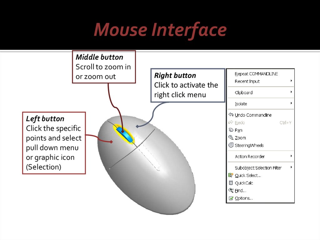
Mouse InterfaceMiddle button
Scroll to zoom in
or zoom out
Left button
Click the specific
points and select
pull down menu
or graphic icon
(Selection)
Right button
Click to activate the
right click menu
38.
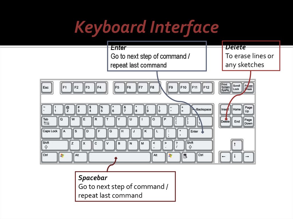
Keyboard InterfaceEnter
Go to next step of command /
repeat last command
Spacebar
Go to next step of command /
repeat last command
Delete
To erase lines or
any sketches