


 programming
Similar presentations:


")

")
Module 1 – Hardware & Installation
1.
NW6000 TRAININGModule 1 – Hardware & Installation
2.
NW6000 TRAINING2
3.
INTRODUCTION• Netwave started as development company for pure 2nd generation of VDRs in 2005
• Headquarters and main production are located in Zoetermeer, the Netherlands
• 1st of June 2011, acquisition of Rutter VDR, making Netwave no. 1 in VDR install base
worldwide
• Install base of 5500 (S)VDRs and still growing…
• NW6000 (S)VDR introduced in 2014 according to IMO MSC.333(90)
• 2017 Netwave acquired by Orolia
• 2021 Netwave acquired by Seas of Solutions
3
4.
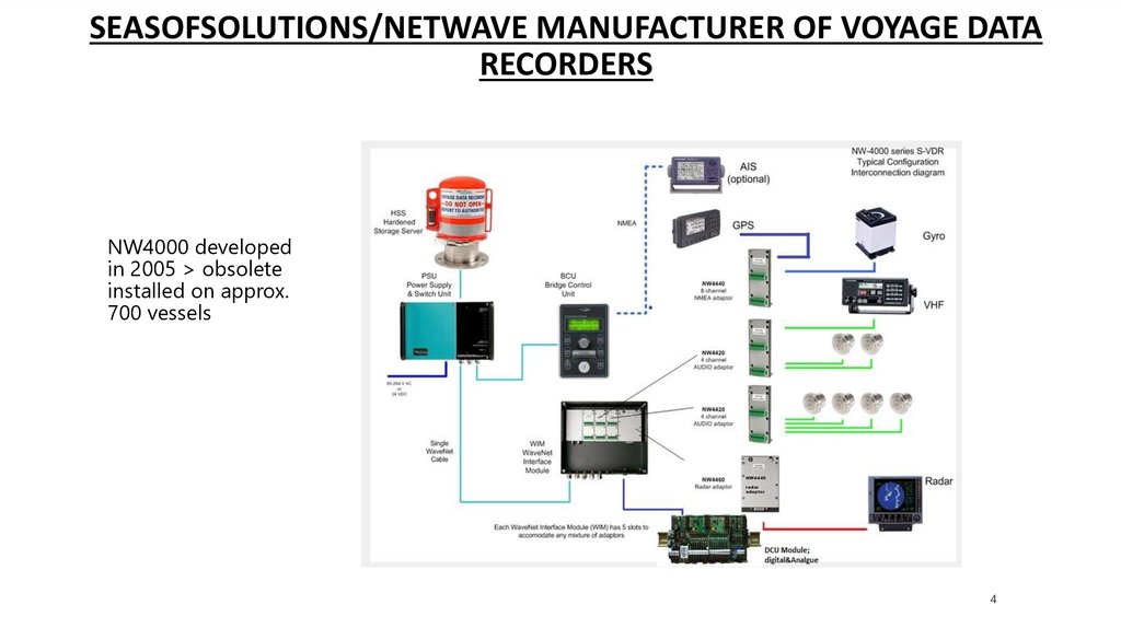
SEASOFSOLUTIONS/NETWAVE MANUFACTURER OF VOYAGE DATARECORDERS
NW4000 developed
in 2005 > obsolete
installed on approx.
700 vessels
4
5.
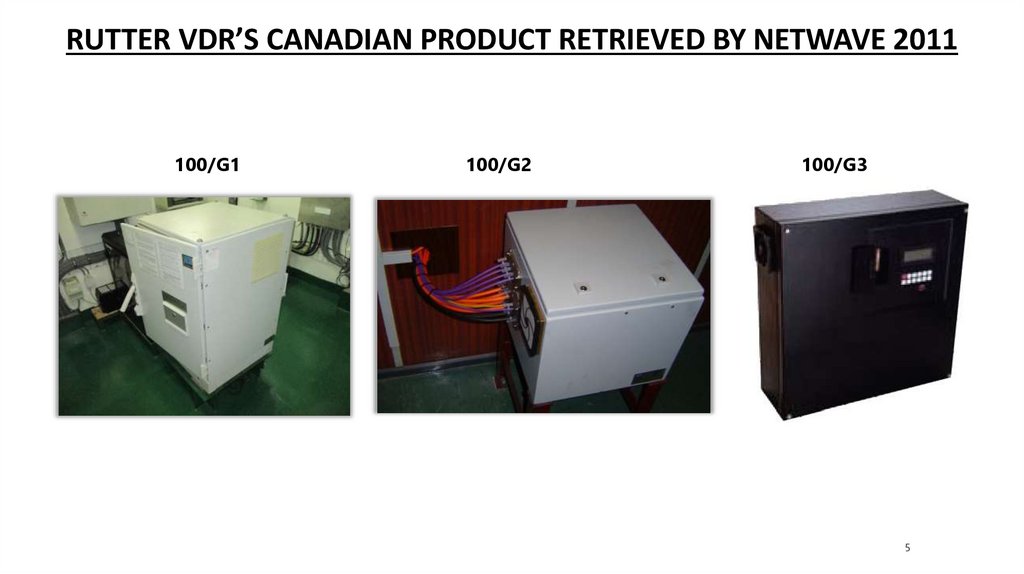
RUTTER VDR’S CANADIAN PRODUCT RETRIEVED BY NETWAVE 2011100/G1
100/G2
100/G3
5
6.
SUPPORT – HELP -APTCONTACT ADDRESSES AND PHONE NR’S
To contact VDR Support: service@seasofsolutions.com
To contact VDR RMA:
rma@seasofsolutions.com
To contact Training:
training@seasofsolutions.com
To contact Sales:
sales@seasofsolutions.com
• Service phone
+31 88 11 81 500
• 16:00-07:00 UTC
+31 62 15 02 167
UPLOADING APT DATA
netwavesystems.wetransfer.com
APT GENERAL QUESTIONS
apts@seasofsolutions.com
6
7.
STAY UPDATED, VISIT OUR PARTNER PORTALGET YOUR USER NAME AND PASSWORD FOR ACCESS VIA OUR SERVICE
DEPARTMENT
VISIT…
WWW.SEASOFSOLUTIONS.COM
8.
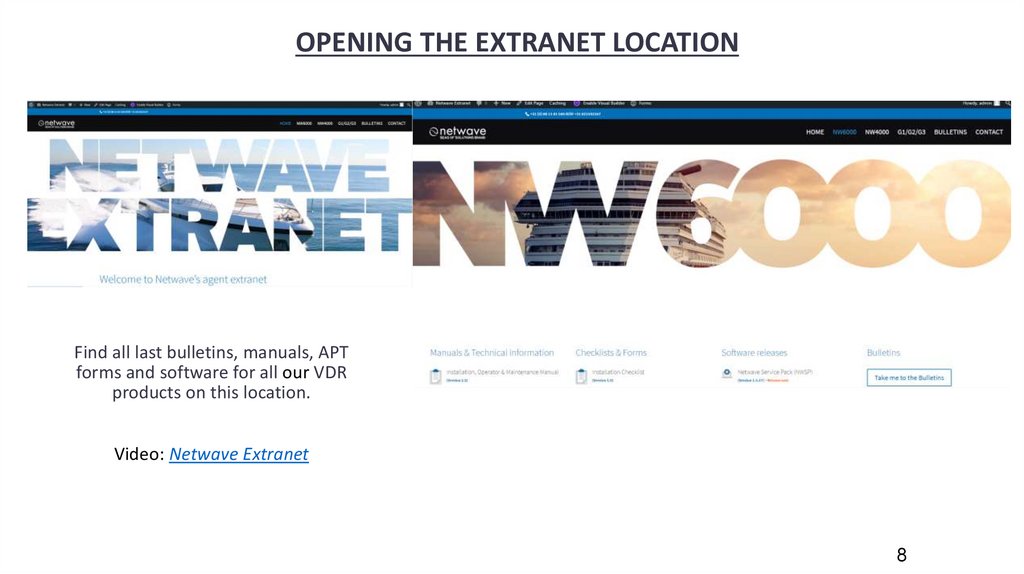
OPENING THE EXTRANET LOCATIONFind all last bulletins, manuals, APT
forms and software for all our VDR
products on this location.
Video: Netwave Extranet
8
9.
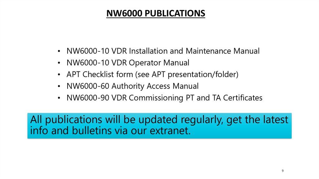
NW6000 PUBLICATIONSNW6000-10 VDR Installation and Maintenance Manual
NW6000-10 VDR Operator Manual
APT Checklist form (see APT presentation/folder)
NW6000-60 Authority Access Manual
NW6000-90 VDR Commissioning PT and TA Certificates
All publications will be updated regularly, get the latest
info and bulletins via our extranet.
9
10.
QUESTIONS?10
11.
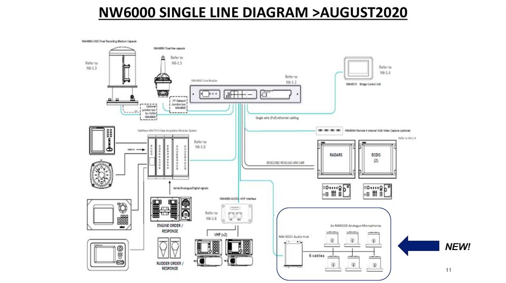
NW6000 SINGLE LINE DIAGRAM >AUGUST2020NEW!
11
12.
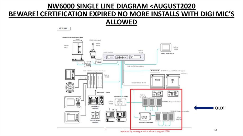
NW6000 SINGLE LINE DIAGRAM <AUGUST2020BEWARE! CERTIFICATION EXPIRED NO MORE INSTALLS WITH DIGI MIC’S
ALLOWED
OLD!
12
13.
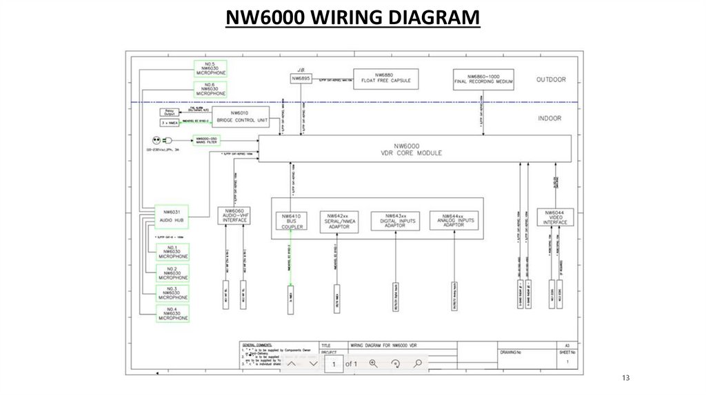
NW6000 WIRING DIAGRAM13
14.
COMPONENTSOF THE
NW6000
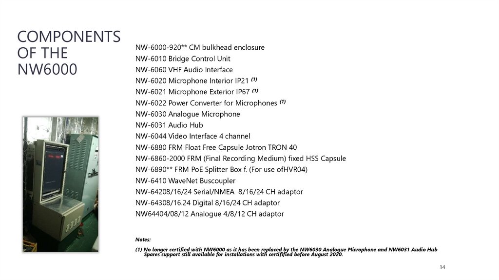
NW-6000-920** CM bulkhead enclosure
NW-6010 Bridge Control Unit
NW-6060 VHF Audio Interface
NW-6020 Microphone Interior IP21 (1)
NW-6021 Microphone Exterior IP67 (1)
NW-6022 Power Converter for Microphones (1)
NW-6030 Analogue Microphone
NW-6031 Audio Hub
NW-6044 Video Interface 4 channel
NW-6880 FRM Float Free Capsule Jotron TRON 40
NW-6860-2000 FRM (Final Recording Medium) fixed HSS Capsule
NW-6890** FRM PoE Splitter Box f. (For use ofHVR04)
NW-6410 WaveNet Buscoupler
NW-64208/16/24 Serial/NMEA 8/16/24 CH adaptor
NW-64308/16.24 Digital 8/16/24 CH adaptor
NW64404/08/12 Analogue 4/8/12 CH adaptor
Notes:
(1) No longer certified with NW6000 as it has been replaced by the NW6030 Analogue Microphone and NW6031 Audio Hub
Spares support still available for installations with certifified before August 2020.
14
15.
COMPONENTS – CORE MODULE NW6000BOur new system is modular and uses Power Over Ethernet.
The main unit named the Core Module, can be located on the bridge or other convenient location like
the electrical equipment room, where a connection can be made with the emergency power source
NW-6000 VDR Core Module (19” enclosure) based in Bulk Head
Inside the Core Module you will find 3 replacable units:
Core Module
• NW-6000-100 CM Power Module
• NW-6000-200 CM Network Module
• NW-6000-300 CM CPU Module
15
16.
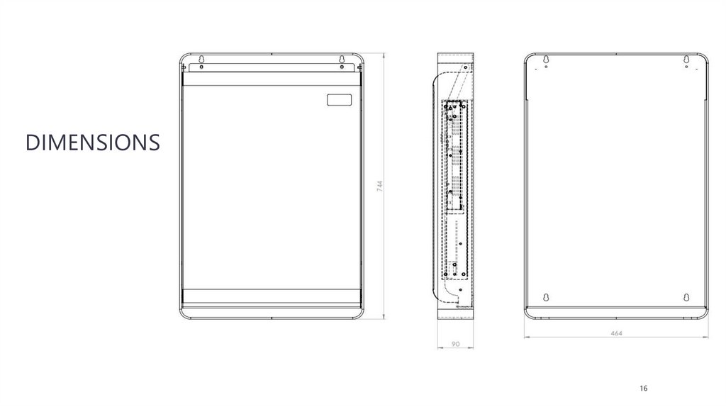
DIMENSIONS16
17.
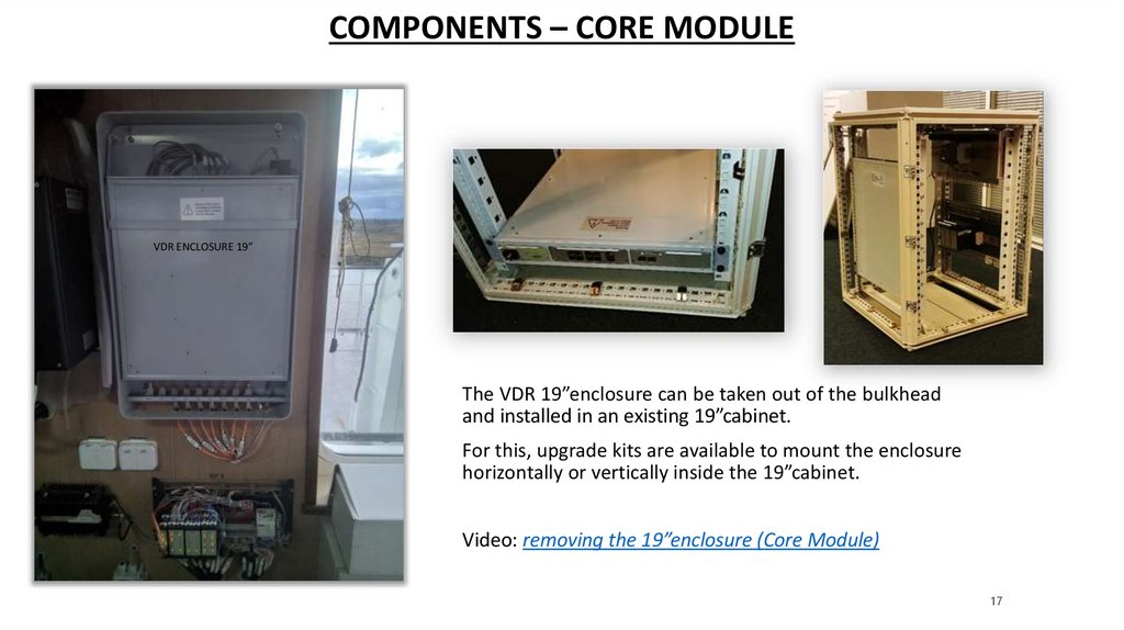
COMPONENTS – CORE MODULEVDR ENCLOSURE 19”
The VDR 19”enclosure can be taken out of the bulkhead
and installed in an existing 19”cabinet.
For this, upgrade kits are available to mount the enclosure
horizontally or vertically inside the 19”cabinet.
Video: removing the 19”enclosure (Core Module)
17
18.
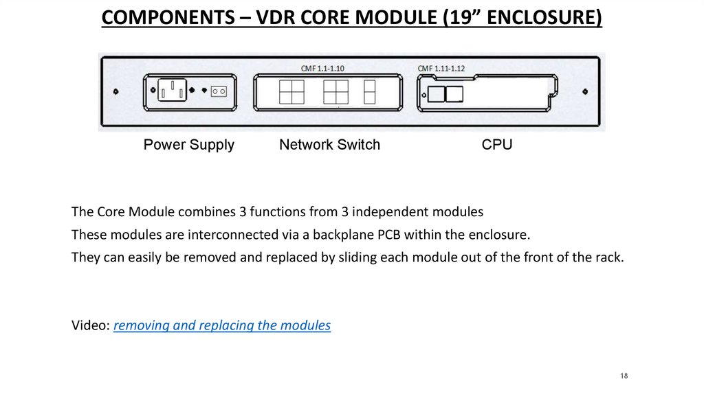
COMPONENTS – VDR CORE MODULE (19” ENCLOSURE)Power Supply
Network Switch
CPU
The Core Module combines 3 functions from 3 independent modules
These modules are interconnected via a backplane PCB within the enclosure.
They can easily be removed and replaced by sliding each module out of the front of the rack.
Video: removing and replacing the modules
18
19.
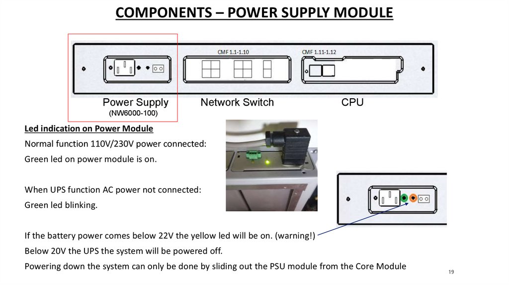
COMPONENTS – POWER SUPPLY MODULEPower Supply
Network Switch
CPU
(NW6000-100)
Led indication on Power Module
Normal function 110V/230V power connected:
Green led on power module is on.
When UPS function AC power not connected:
Green led blinking.
If the battery power comes below 22V the yellow led will be on. (warning!)
Below 20V the UPS the system will be powered off.
Powering down the system can only be done by sliding out the PSU module from the Core Module
19
20.
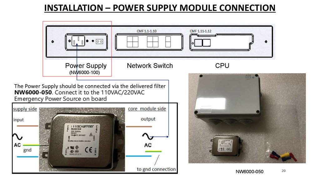
INSTALLATION – POWER SUPPLY MODULE CONNECTIONPower Supply
Network Switch
CPU
(NW6000-100)
The Power Supply should be connected via the delivered filter
NW6000-050. Connect it to the 110VAC/220VAC
Emergency Power Source on board
NW6000-050
20
21.
COMPONENTS – POWER SUPPLY MODULEPower Supply
Network Switch
CPU
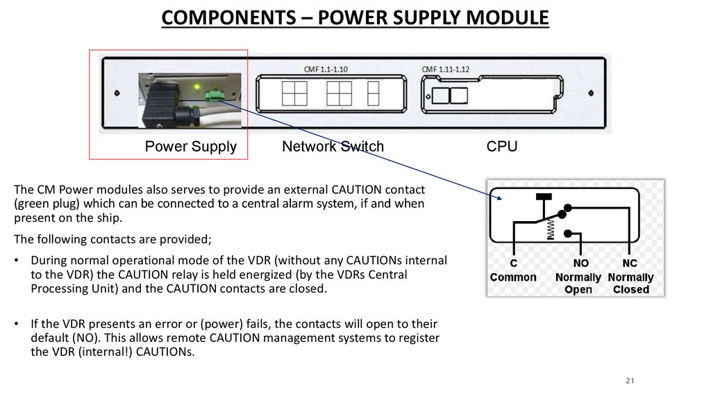
The CM Power modules also serves to provide an external CAUTION contact
(green plug) which can be connected to a central alarm system, if and when
present on the ship.
The following contacts are provided;
• During normal operational mode of the VDR (without any CAUTIONs internal
to the VDR) the CAUTION relay is held energized (by the VDRs Central
Processing Unit) and the CAUTION contacts are closed.
• If the VDR presents an error or (power) fails, the contacts will open to their
default (NO). This allows remote CAUTION management systems to register
the VDR (internal!) CAUTIONs.
21
22.
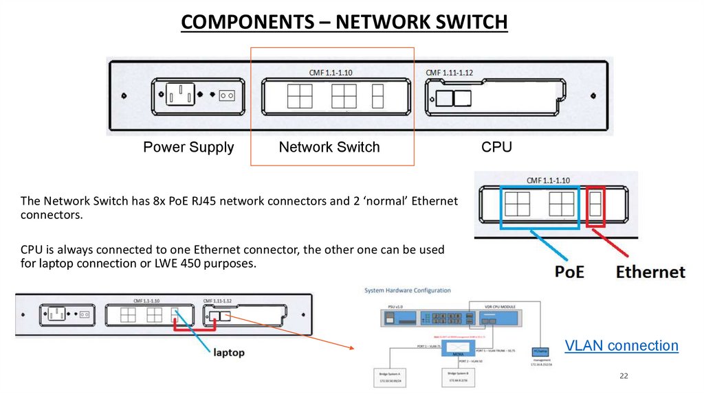
COMPONENTS – NETWORK SWITCHPower Supply
Network Switch
CPU
The Network Switch has 8x PoE RJ45 network connectors and 2 ‘normal’ Ethernet
connectors.
CPU is always connected to one Ethernet connector, the other one can be used
for laptop connection or LWE 450 purposes.
Not Used
VLAN connection
22
23.
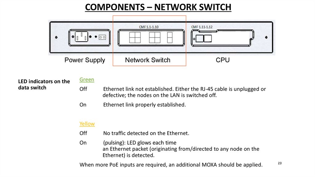
COMPONENTS – NETWORK SWITCHPower Supply
LED indicators on the
data switch
Network Switch
CPU
Green
Off
Ethernet link not established. Either the RJ-45 cable is unplugged or
defective; the nodes on the LAN is switched off.
On
Ethernet link properly established.
Yellow
Off
No traffic detected on the Ethernet.
On
(pulsing): LED glows each time
an Ethernet packet (originating from/directed to any node on the
Ethernet) is detected.
When more PoE inputs are required, an additional MOXA should be applied.
23
24.
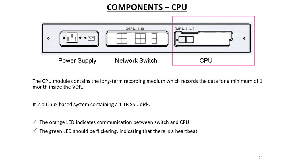
COMPONENTS – CPUPower Supply
Network Switch
CPU
The CPU module contains the long-term recording medium which records the data for a minimum of 1
month inside the VDR.
It is a Linux based system containing a 1 TB SSD disk.
The orange LED indicates communication between switch and CPU
The green LED should be flickering, indicating that there is a heartbeat
24
25.
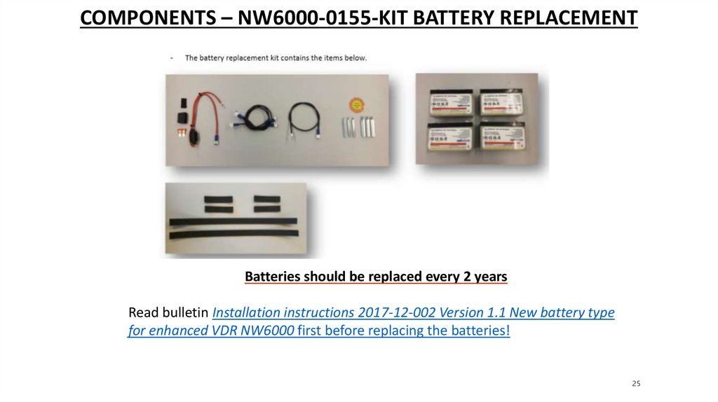
COMPONENTS – NW6000-0155-KIT BATTERY REPLACEMENTBatteries should be replaced every 2 years
Read bulletin Installation instructions 2017-12-002 Version 1.1 New battery type
for enhanced VDR NW6000 first before replacing the batteries!
25
26.
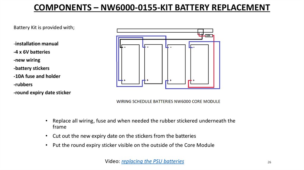
COMPONENTS – NW6000-0155-KIT BATTERY REPLACEMENTBattery Kit is provided with;
-installation manual
-4 x 6V batteries
-new wiring
-battery stickers
-10A fuse and holder
-rubbers
-round expiry date sticker
• Replace all wiring, fuse and when needed the rubber stickered underneath the
frame
• Cut out the new expiry date on the stickers from the batteries
• Put the round expiry sticker visible on the outside of the Core Module
Video: replacing the PSU batteries
26
27.
QUESTIONS?27
28.
INSTALLATION - CORE MODULEThe CM (Core Module) is powered from the emergency backup power source which should be
100-264V AC (+/- 10%) 50 - 60Hz with a maximum frequency deviation of 5% (IEC60945). The
power consumption is rated at maximum of 150W for the entire VDR system, thus including all
PoE (Power over Ethernet) connections (up to 15W each). This power consumption does not
include any devices external to the VDR where these must be powered individually from the
ship’s power source.
Mains power cables: type: 3-core mains, flame retardant, halogen free. The power-connector
and cable are provided within the standard scope of supply and indication for the position for
the L (Brown), N (Blue) and GND (Yellow/Green) connections are also indicated within the plugconnector.
The leads must be connected to the supply as follows;
Brown
L
Blue
N
Yellow/Green
Ground
The 3 leads (L,N,GND) must have a minimal diameter of 1 mm2
28
29.
INSTALLATION CORE MODULE – MOUNTINGIf the bulkhead-mounting enclosure is used, mount the bracket with your choice of bolts
supplied with the unit.
Disconnect all plugs and take out the Core Module so you can easily mount the bulkhead
Make sure the bracket is mounted with the slotted holes in the correct vertical direction.
Keep 50 mm of free space above the bracket to provide sufficient ventilation for this unit.
Slide the CM into the cabinet or bulkhead enclosure by making use of the hinges and
screw/tighten the 2 bolts at the back to secure the unit.
Connect the Ground stud to a suitable safety ground.
29
30.
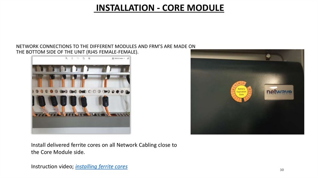
INSTALLATION - CORE MODULENETWORK CONNECTIONS TO THE DIFFERENT MODULES AND FRM’S ARE MADE ON
THE BOTTOM SIDE OF THE UNIT (RJ45 FEMALE-FEMALE).
Install delivered ferrite cores on all Network Cabling close to
the Core Module side.
Instruction video; installing ferrite cores
30
31.
INSTALLATION - CORE MODULEEXAMPLES
31
32.
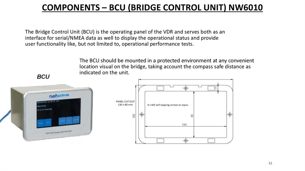
COMPONENTS – BCU (BRIDGE CONTROL UNIT) NW6010The Bridge Control Unit (BCU) is the operating panel of the VDR and serves both as an
interface for serial/NMEA data as well to display the operational status and provide
user functionality like, but not limited to, operational performance tests.
BCU
The BCU should be mounted in a protected environment at any convenient
location visual on the bridge, taking account the compass safe distance as
indicated on the unit.
32
33.
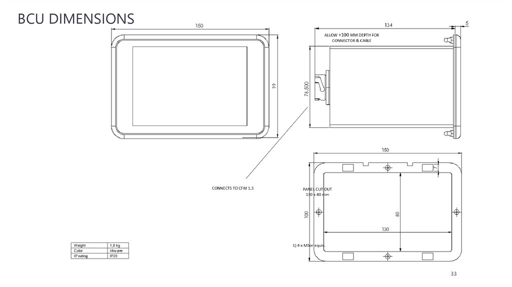
BCU DIMENSIONS33
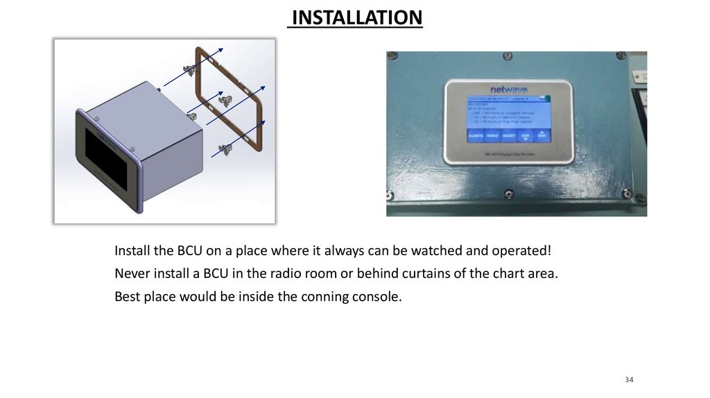
34.
INSTALLATIONInstall the BCU on a place where it always can be watched and operated!
Never install a BCU in the radio room or behind curtains of the chart area.
Best place would be inside the conning console.
34
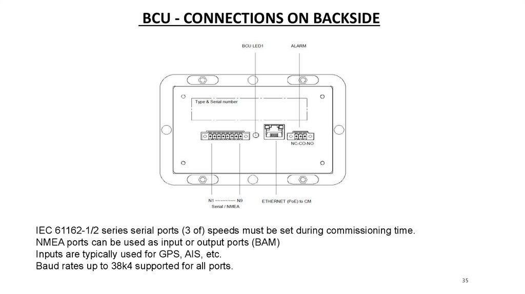
35.
BCU - CONNECTIONS ON BACKSIDEIEC 61162-1/2 series serial ports (3 of) speeds must be set during commissioning time.
NMEA ports can be used as input or output ports (BAM)
Inputs are typically used for GPS, AIS, etc.
Baud rates up to 38k4 supported for all ports.
35
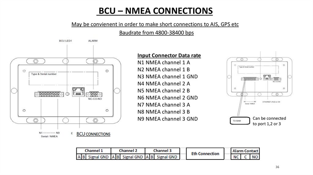
36.
BCU – NMEA CONNECTIONSMay be convienent in order to make short connections to AIS, GPS etc
Baudrate from 4800-38400 bps
Input Connector Data rate
N1 NMEA channel 1 A
N2 NMEA channel 1 B
N3 NMEA channel 1 GND
N4 NMEA channel 2 A
N5 NMEA channel 2 B
N6 NMEA channel 2 GND
N7 NMEA channel 3 A
N8 NMEA channel 3 B
N9 NMEA channel 3 GND
Can be connected
to port 1,2 or 3
36
37.
BCU – NMEA CONNECTIONS37
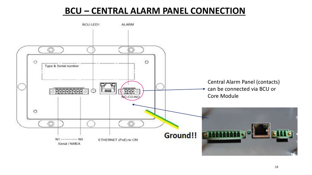
38.
BCU – CENTRAL ALARM PANEL CONNECTIONCentral Alarm Panel (contacts)
can be connected via BCU or
Core Module
38
39.
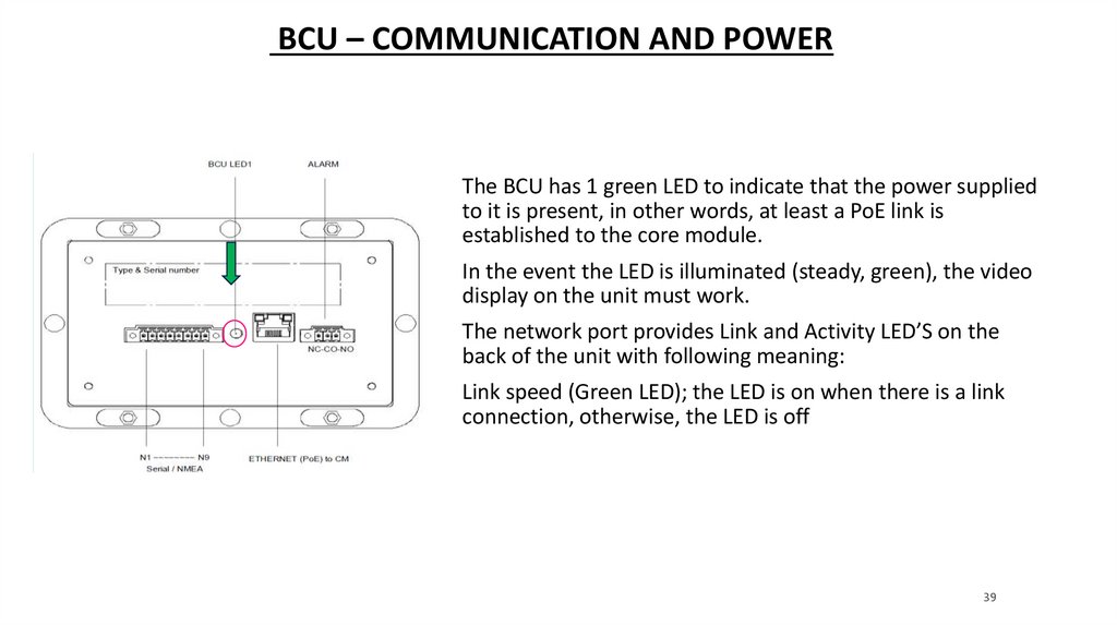
BCU – COMMUNICATION AND POWERThe BCU has 1 green LED to indicate that the power supplied
to it is present, in other words, at least a PoE link is
established to the core module.
In the event the LED is illuminated (steady, green), the video
display on the unit must work.
The network port provides Link and Activity LED’S on the
back of the unit with following meaning:
Link speed (Green LED); the LED is on when there is a link
connection, otherwise, the LED is off
39
40.
BCU – ERROR INDICATIONIn the event the LED on the back side of the unit is On,
the display is illuminated and showing text (buttons),
but when no valid (UTC) time is presented on the display,
the data-link to the core module is not functional at that
time.
Click to add text
All other errors are presented on the display.
40
41.
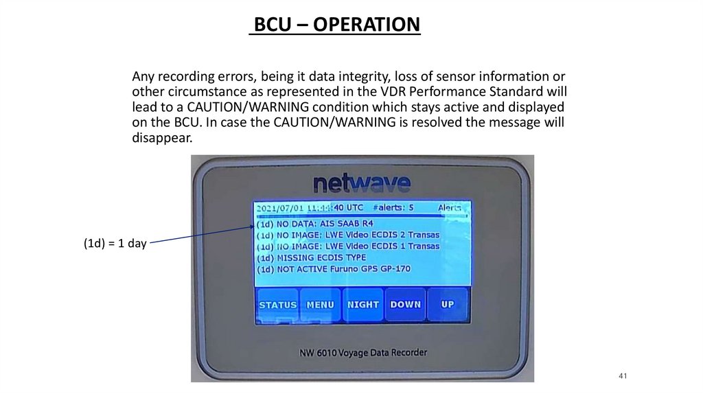
BCU – OPERATIONAny recording errors, being it data integrity, loss of sensor information or
other circumstance as represented in the VDR Performance Standard will
lead to a CAUTION/WARNING condition which stays active and displayed
on the BCU. In case the CAUTION/WARNING is resolved the message will
disappear.
(1d) = 1 day
41
42.
BCU – UNITS OR DEVICES (WARNING)In the event of network-absence or malfunction of any hardware device a
Warning will be generated.
These Warnings relate to communications errors
(HSS server), temperature overflow, absence of power, memory storage
space, etc.
A Warning will occur if any of the microphones becomes
dysfunctional. Every microphone is automatically tested every 12
hours.
42
43.
BCU – OPERATIONAL PERFORMANCE TEST• Can be conducted on the BCU
• Will test all incoming signals
• Must be carried out on board (by Cpt. crew) at least 10x (monthly) every
Year
• Log file's will be created, can displayed after download and must be checked
during APT
Video: BCU instructional movie
43
44.
QUESTIONS?44
45.
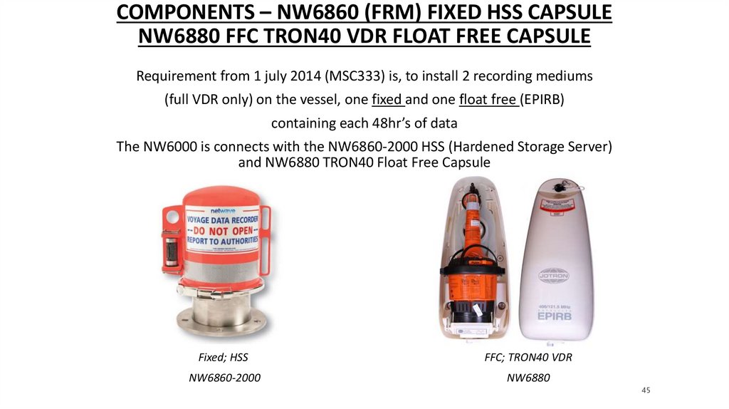
COMPONENTS – NW6860 (FRM) FIXED HSS CAPSULENW6880 FFC TRON40 VDR FLOAT FREE CAPSULE
Requirement from 1 july 2014 (MSC333) is, to install 2 recording mediums
(full VDR only) on the vessel, one fixed and one float free (EPIRB)
containing each 48hr’s of data
The NW6000 is connects with the NW6860-2000 HSS (Hardened Storage Server)
and NW6880 TRON40 Float Free Capsule
Fixed; HSS
FFC; TRON40 VDR
NW6860-2000
NW6880
45
46.
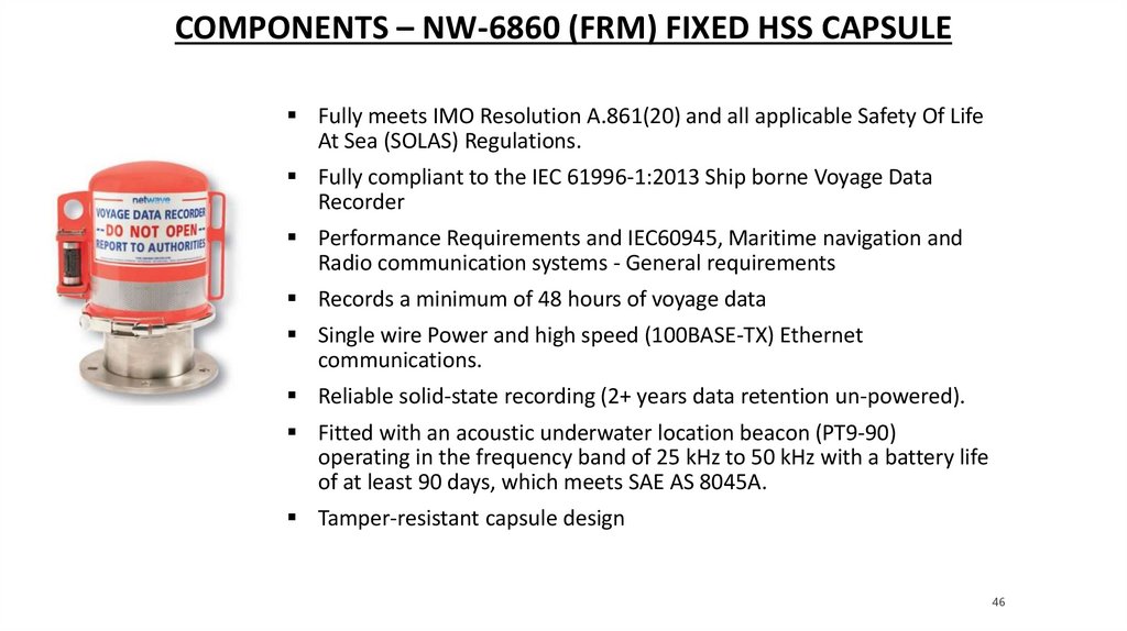
COMPONENTS – NW-6860 (FRM) FIXED HSS CAPSULEFully meets IMO Resolution A.861(20) and all applicable Safety Of Life
At Sea (SOLAS) Regulations.
Fully compliant to the IEC 61996-1:2013 Ship borne Voyage Data
Recorder
Performance Requirements and IEC60945, Maritime navigation and
Radio communication systems - General requirements
Records a minimum of 48 hours of voyage data
Single wire Power and high speed (100BASE-TX) Ethernet
communications.
Reliable solid-state recording (2+ years data retention un-powered).
Fitted with an acoustic underwater location beacon (PT9-90)
operating in the frequency band of 25 kHz to 50 kHz with a battery life
of at least 90 days, which meets SAE AS 8045A.
Tamper-resistant capsule design
46
47.
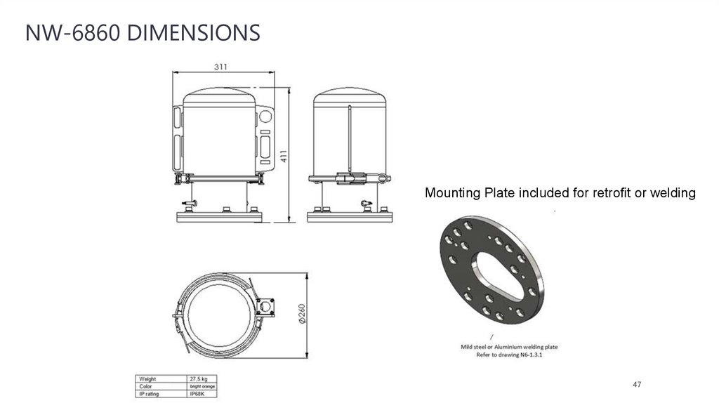
NW-6860 DIMENSIONSMounting Plate included for retrofit or welding
47
48.
COMPONENTS – NW6860 FIXED CAPSULE MEMORY CAPACITY 64GBThe capsule shall be positioned clear of
rigging and other potential obstructions
and as near to the centerline of the ship
as practically possible
This unit has 1 x 100BASE-TX PoE port, receiving 802.3af
compliant PoE @48V and fully relies on the Ethernet PoE
supplied from the Core Module. The total power budget for the
capsule is 2.5 Watts
HSS is provided with an RJ45 connector in order to connect the
Poe Cable, not included, cable can be ordered, contact sales
department
48
49.
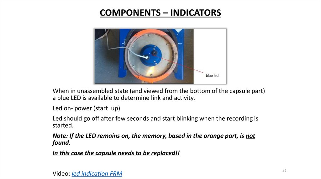
COMPONENTS – INDICATORSWhen in unassembled state (and viewed from the bottom of the capsule part)
a blue LED is available to determine link and activity.
Led on- power (start up)
Led should go off after few seconds and start blinking when the recording is
started.
Note: If the LED remains on, the memory, based in the orange part, is not
found.
In this case the capsule needs to be replaced!!
Video: led indication FRM
49
50.
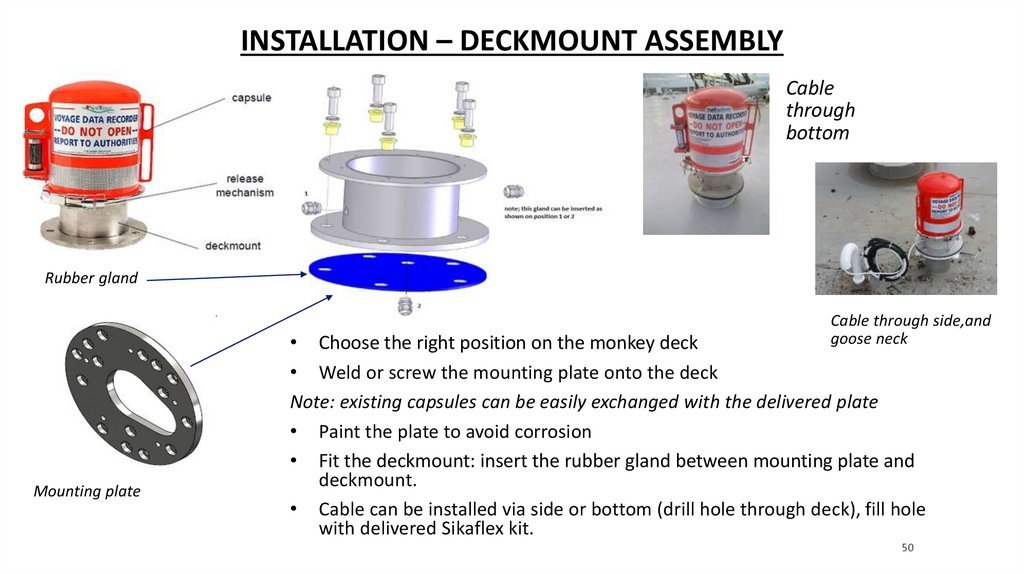
INSTALLATION – DECKMOUNT ASSEMBLYCable
through
bottom
Rubber gland
Cable through side,and
goose neck
Mounting plate
• Choose the right position on the monkey deck
• Weld or screw the mounting plate onto the deck
Note: existing capsules can be easily exchanged with the delivered plate
• Paint the plate to avoid corrosion
• Fit the deckmount: insert the rubber gland between mounting plate and
deckmount.
• Cable can be installed via side or bottom (drill hole through deck), fill hole
with delivered Sikaflex kit.
50
51.
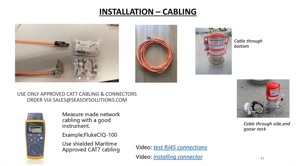
INSTALLATION – CABLINGCable through
bottom
USE ONLY APPROVED CAT7 CABLING & CONNECTORS
ORDER VIA SALES@SEASOFSOLUTIONS.COM
Measure made network
cabling with a good
instrument.
Cable through side,and
goose neck
Example;FlukeCIQ-100
Use shielded Maritime
Approved CAT7 cabling
Video: test RJ45 connections
Video: installing connector
51
52.
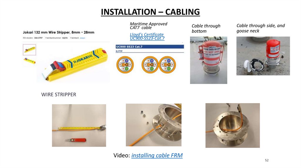
INSTALLATION – CABLINGMaritime Approved
CAT7 cable
Lloyd's Certificate
UC900-SS23-Cat.7
Cable through
bottom
Cable through side, and
goose neck
WIRE STRIPPER
Video: installing cable FRM
52
53.
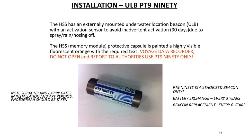
INSTALLATION – ULB PT9 NINETYThe HSS has an externally mounted underwater location beacon (ULB)
with an activation sensor to avoid inadvertent activation (90 days)due to
spray/rain/hosing off.
The HSS (memory module) protective capsule is painted a highly visible
fluorescent orange with the required text: VOYAGE DATA RECORDER,
DO NOT OPEN and REPORT TO AUTHORITIES USE PT9 NINETY ONLY!
NOTE SERIAL NR AND EXPIRY DATES
IN INSTALLATION AND APT REPORTS,
PHOTOGRAPH SHOULD BE TAKEN
PT9 NINETY IS AUTHORISED BEACON
ONLY!
BATTERY EXCHANGE – EVERY 3 YEARS
BEACON REPLACEMENT– EVERY 6 YEARS
53
54.
MAINTENANCE – ULB NW4860-695The ULB battery should be replaced after 3 years.
Battery kit NW4860-693 should be ordered and replacement
instructions followed.
The beacon should be tested every year during APT.
Manual: Netwave PT9 NINETY Manual
Video: ULB battery replacement
54
55.
PROCEDURE – ULB NW4860-695Take the ULB from the capsule
Replace the battery with the battery tool NW4860-594
Place the new expiry sticker on the label
Put the new expiry date in the APT report
Test the beacon and mention test results in the report
Provide a photo with your data content to be send
NW4860-594 battery replacement tool
55
56.
QUESTIONS?56
57.
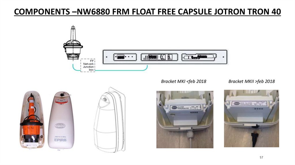
COMPONENTS –NW6880 FRM FLOAT FREE CAPSULE JOTRON TRON 40Bracket MKI <feb 2018
Bracket MKII >feb 2018
57
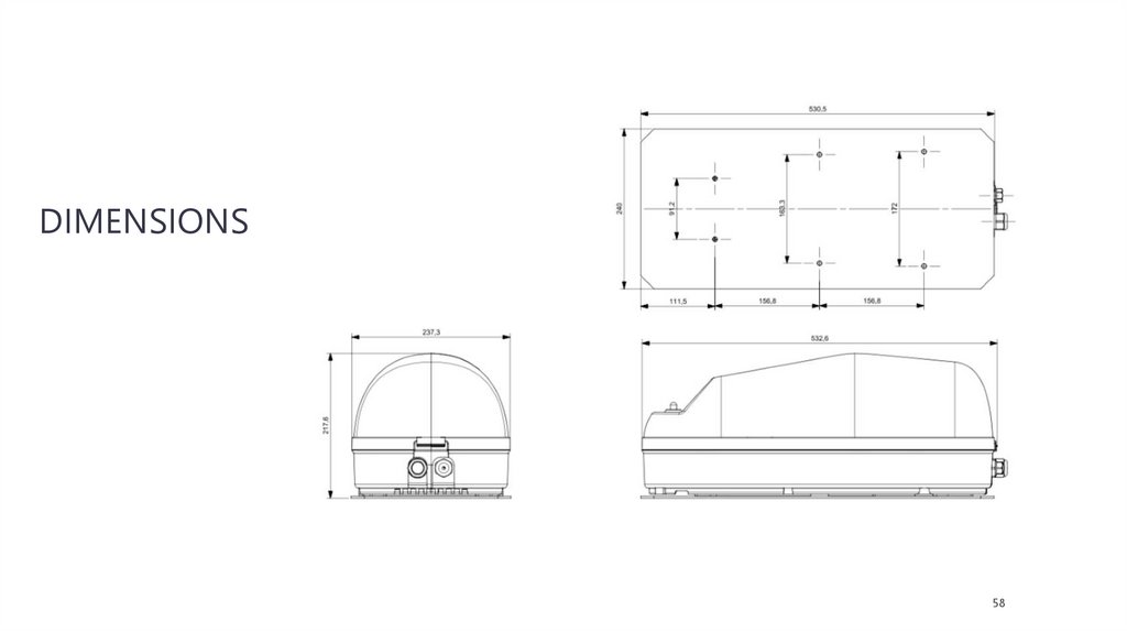
58.
DIMENSIONS58
59.
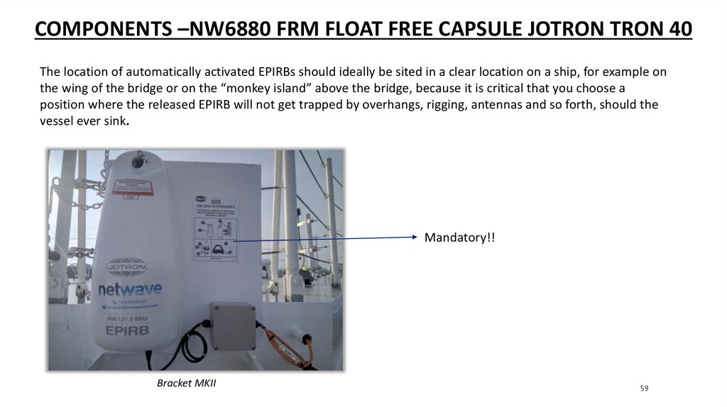
COMPONENTS –NW6880 FRM FLOAT FREE CAPSULE JOTRON TRON 40The location of automatically activated EPIRBs should ideally be sited in a clear location on a ship, for example on
the wing of the bridge or on the “monkey island” above the bridge, because it is critical that you choose a
position where the released EPIRB will not get trapped by overhangs, rigging, antennas and so forth, should the
vessel ever sink.
Mandatory!!
Bracket MKII
59
60.
INSTALLATION –NW6880 FRM FLOAT FREE CAPSULE JOTRON TRON 40- It is not recommended to locate the TRON 40VDR on the compass deck because of high risk of exposure to
strong RF signals.
- Find a (new) mounting location as far away as possible from any radar interference and/or other antennas
conform Jotron specifications (see Jotron installation manual). Make sure the TRON 40VDR is not directly in
line of sight of any radar, and at least 3 meters away from any antenna.
- Stronger antenna signals (than the TRON 40VDR is approved for) can affect the VDR storage performance.
The TRON 40VDR is approved for 100 V/m in the VHF frequency range 156 - 165 MHz. In other areas of the
frequency range 150 KHz - 2 GHz the requirement is 10 V/m. A standard VHF antenna will have 10 V/m at
distance of 3 meters in the antenna lobe. Therefore, the absolute minimum distance to a VHF antenna, at
the same height needs to be no less than 3 meters. It is strongly recommended to have a much larger
distance to other transmitting antennas.
- RF signals from transmitting antennas are likely to be weaker at low levels. Therefore, reduction of
interference may be achieved by installing the TRON 40VDR lower than all transmitting antennas.
60
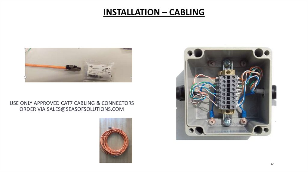
61.
INSTALLATION – CABLINGUSE ONLY APPROVED CAT7 CABLING & CONNECTORS
ORDER VIA SALES@SEASOFSOLUTIONS.COM
61
62.
INSTALLATION – HARDWAREMOUNT THE TRON40 ON A STEEL PLATE AND INSTALL IT IN VERTICAL POSITION
READ BULLETIN TB01-2015
Install the
delivered
instrucion plate
next to the
bracket
Don’t forget to
install this plate!!
It’s mandatory
Don’t install too
close to the floor,
this is correct!
62
63.
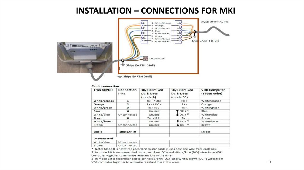
INSTALLATION – CONNECTIONS FOR MKI63
64.
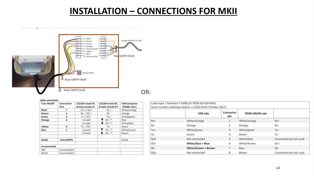
INSTALLATION – CONNECTIONS FOR MKIIOR:
64
65.
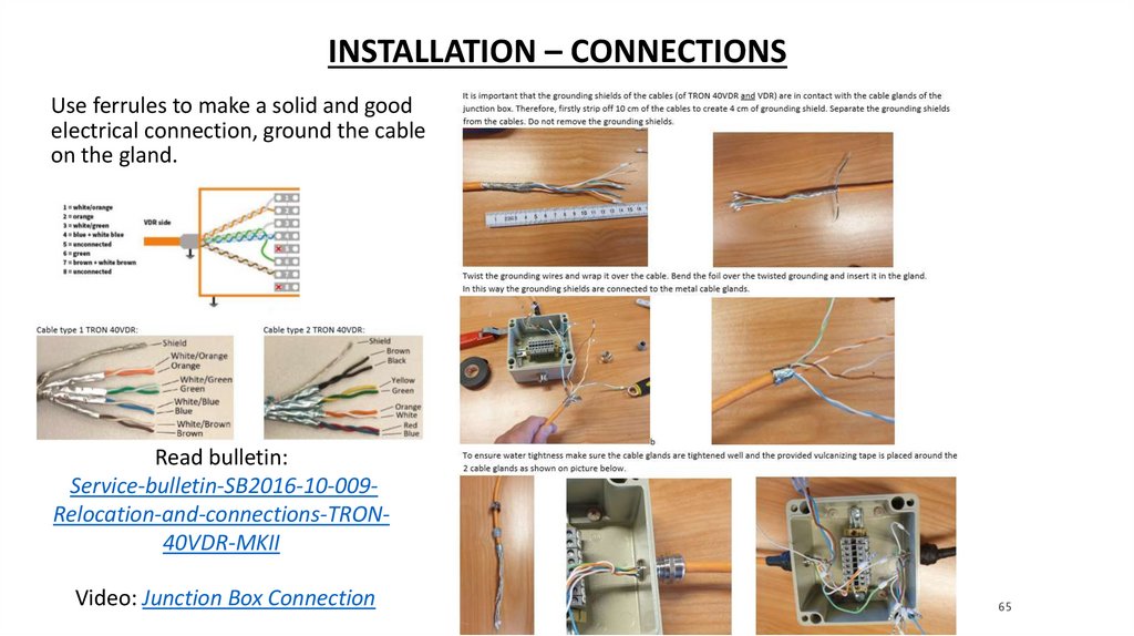
INSTALLATION – CONNECTIONSUse ferrules to make a solid and good
electrical connection, ground the cable
on the gland.
Read bulletin:
Service-bulletin-SB2016-10-009Relocation-and-connections-TRON40VDR-MKII
Video: Junction Box Connection
65
66.
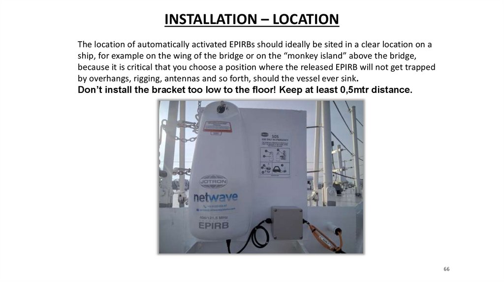
INSTALLATION – LOCATIONThe location of automatically activated EPIRBs should ideally be sited in a clear location on a
ship, for example on the wing of the bridge or on the “monkey island” above the bridge,
because it is critical that you choose a position where the released EPIRB will not get trapped
by overhangs, rigging, antennas and so forth, should the vessel ever sink.
Don’t install the bracket too low to the floor! Keep at least 0,5mtr distance.
66
67.
LED INDICATION – BRACKETGreen LED’s identification on the bracket explained:
Bracket MKII >feb 2018
Bracket MKI <feb 2018
Video: LED indication TRON40
67
68.
QUESTIONS?68
69.
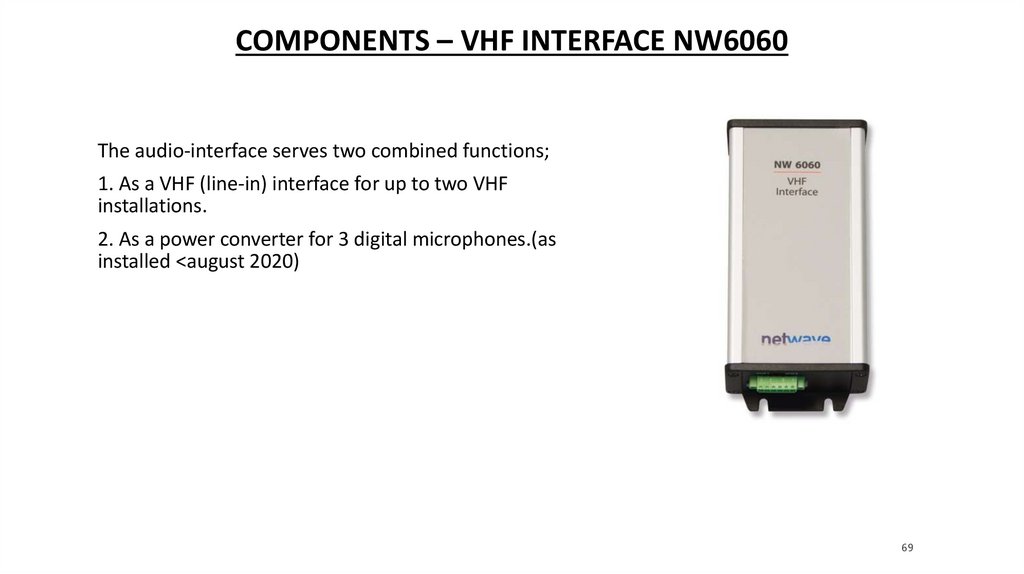
COMPONENTS – VHF INTERFACE NW6060The audio-interface serves two combined functions;
1. As a VHF (line-in) interface for up to two VHF
installations.
2. As a power converter for 3 digital microphones.(as
installed <august 2020)
69
70.
CONNECTIONS – VHF INTERFACE NW6060Digital mic’s NW6020/6021 used < august 2020
Systems are still running in old s/w and playback s/w
70
71.
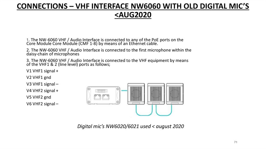
CONNECTIONS – VHF INTERFACE NW6060 WITH OLD DIGITAL MIC’S<AUG2020
1. The NW-6060 VHF / Audio Interface is connected to any of the PoE ports on the
Core Module Core Module (CMF 1-8) by means of an Ethernet cable.
2. The NW-6060 VHF / Audio Interface is connected to the first microphone within the
daisy-chain of microphones
3. The NW-6060 VHF / Audio Interface is connected to the VHF equipment by means
of the VHF1 & 2 (line level) ports as follows;
V1 VHF1 signal +
V2 VHF1 gnd
V3 VHF1 signal –
V4 VHF2 signal +
V5 VHF2 gnd
V6 VHF2 signal –
Digital mic’s NW6020/6021 used < august 2020
71
72.
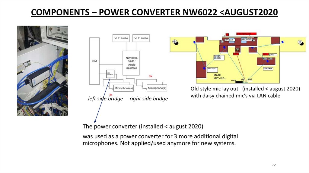
COMPONENTS – POWER CONVERTER NW6022 <AUGUST2020left side bridge
right side bridge
Old style mic lay out (installed < august 2020)
with daisy chained mic’s via LAN cable
The power converter (installed < august 2020)
was used as a power converter for 3 more additional digital
microphones. Not applied/used anymore for new systems.
72
73.
COMPONENTS – CONFIGURATION <AUGUST2020The individual microphone and VHF channel’s IPaddresses are set during commissioning time.
Please refer to VDR Configuration old style.
See presentation 13. old style NW6000
Configuration and Playback 1.5.17 systems
73
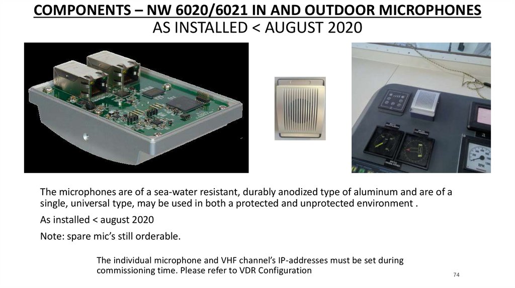
74.
COMPONENTS – NW 6020/6021 IN AND OUTDOOR MICROPHONESAS INSTALLED < AUGUST 2020
The microphones are of a sea-water resistant, durably anodized type of aluminum and are of a
single, universal type, may be used in both a protected and unprotected environment .
As installed < august 2020
Note: spare mic’s still orderable.
The individual microphone and VHF channel’s IP-addresses must be set during
commissioning time. Please refer to VDR Configuration
74
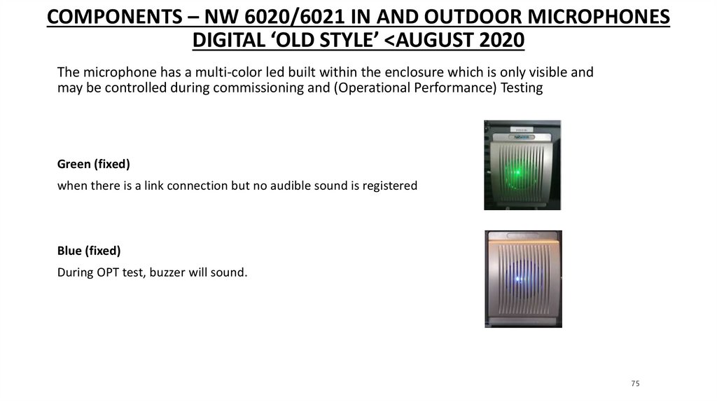
75.
COMPONENTS – NW 6020/6021 IN AND OUTDOOR MICROPHONESDIGITAL ‘OLD STYLE’ <AUGUST 2020
The microphone has a multi-color led built within the enclosure which is only visible and
may be controlled during commissioning and (Operational Performance) Testing
Green (fixed)
when there is a link connection but no audible sound is registered
Blue (fixed)
During OPT test, buzzer will sound.
75
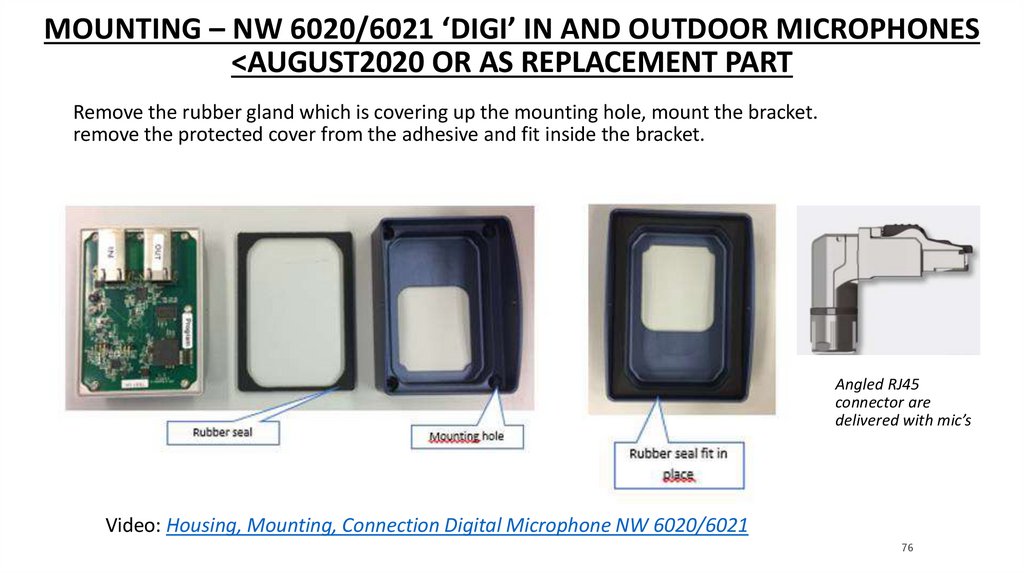
76.
MOUNTING – NW 6020/6021 ‘DIGI’ IN AND OUTDOOR MICROPHONES<AUGUST2020 OR AS REPLACEMENT PART
Remove the rubber gland which is covering up the mounting hole, mount the bracket.
remove the protected cover from the adhesive and fit inside the bracket.
Angled RJ45
connector are
delivered with mic’s
Video: Housing, Mounting, Connection Digital Microphone NW 6020/6021
76
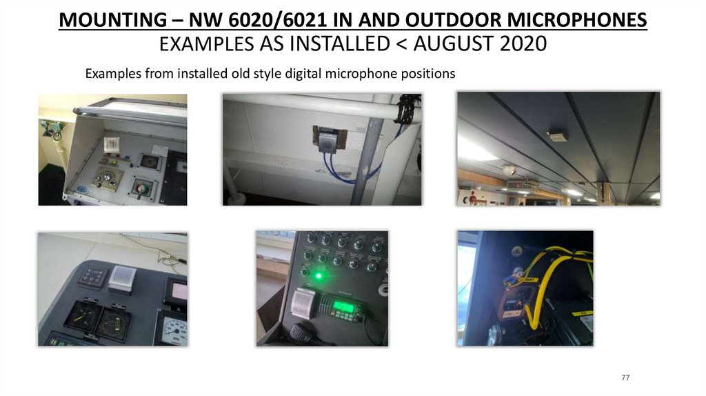
77.
MOUNTING – NW 6020/6021 IN AND OUTDOOR MICROPHONESEXAMPLES AS INSTALLED < AUGUST 2020
Examples from installed old style digital microphone positions
77
78.
QUESTIONS?78
79.
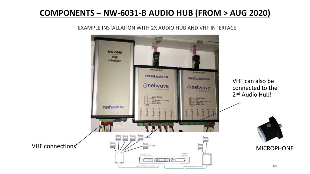
AUDIO COMPONENTS – NW-6031-B AUDIO HUB (FROM > AUG 2020)The Audio Hub is contained in an extruded aluminium housing. The NW6031 Audio Hub is powered using PoE
from the NW6000 and provides 6 audio input channels which are simultaneously sampled.
Digital processing used within the hub to convert sampled analogue data for communications back to the
NW6000 over the PoE communications port.
LAN input
The NW6031 has no external
indicators with the exception of the
Ethernet communications indicators
on the RJ45 socket.
Link speed (Green LED)The LED is on
when there is a link connection.
Otherwise, the LED is off.
Activity (Yellow LED)The LED is flashing
when there is activity on the link.
Otherwise, the LED is off.
79
80.
COMPONENTS – NW-6031-B AUDIO HUB (FROM > AUG 2020)EXAMPLE INSTALLATION WITH 2X AUDIO HUB AND VHF INTERFACE
VHF can also be
connected to the
2nd Audio Hub!
VHF connections
MICROPHONE
80
81.
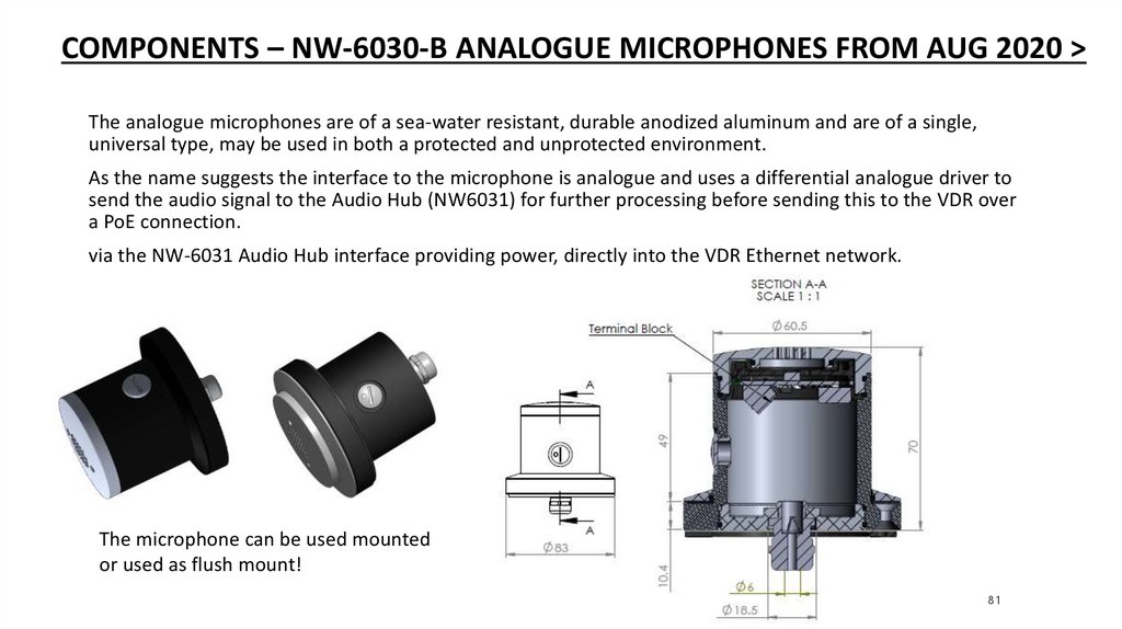
COMPONENTS – NW-6030-B ANALOGUE MICROPHONES FROM AUG 2020 >The analogue microphones are of a sea-water resistant, durable anodized aluminum and are of a single,
universal type, may be used in both a protected and unprotected environment.
As the name suggests the interface to the microphone is analogue and uses a differential analogue driver to
send the audio signal to the Audio Hub (NW6031) for further processing before sending this to the VDR over
a PoE connection.
via the NW-6031 Audio Hub interface providing power, directly into the VDR Ethernet network.
The microphone can be used mounted
or used as flush mount!
81
82.
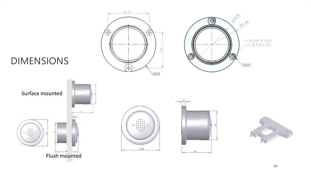
DIMENSIONSSurface mounted
Flush mounted
82
83.
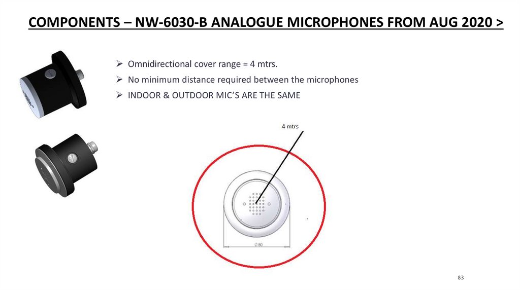
COMPONENTS – NW-6030-B ANALOGUE MICROPHONES FROM AUG 2020 >Omnidirectional cover range = 4 mtrs.
No minimum distance required between the microphones
INDOOR & OUTDOOR MIC’S ARE THE SAME
83
84.
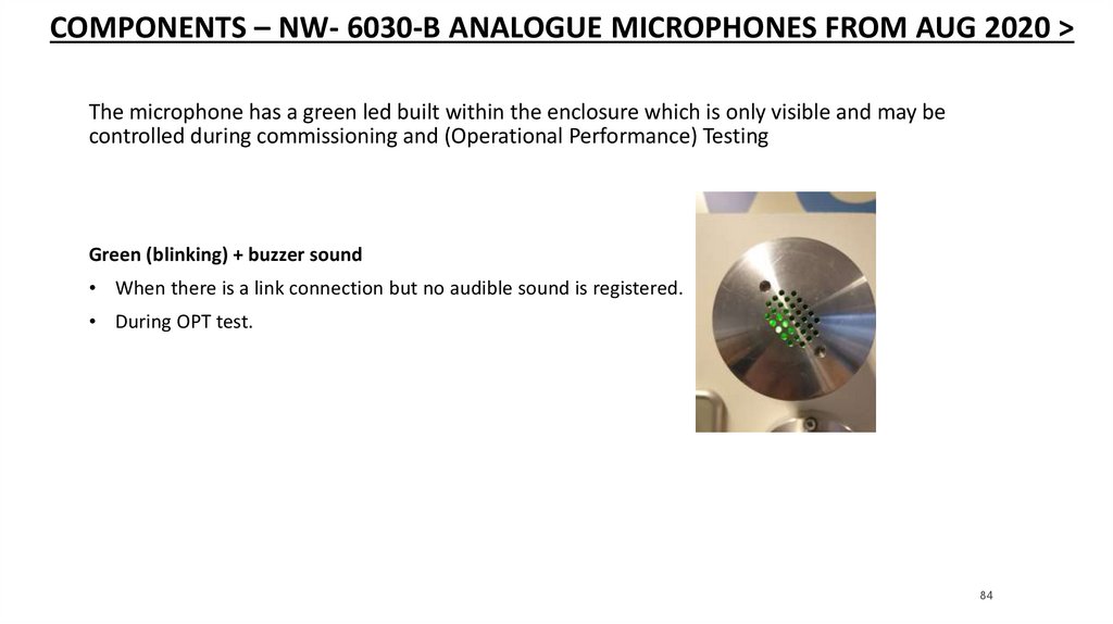
COMPONENTS – NW- 6030-B ANALOGUE MICROPHONES FROM AUG 2020 >The microphone has a green led built within the enclosure which is only visible and may be
controlled during commissioning and (Operational Performance) Testing
Green (blinking) + buzzer sound
• When there is a link connection but no audible sound is registered.
• During OPT test.
84
85.
CONNECTIONS – NW- 6030-B ANALOGUE MICROPHONESAudio-cabling from HUB to Mic should be 2 pair twisted shielded to avoid interference issues
Existing cabling can be re-used again.
85
86.
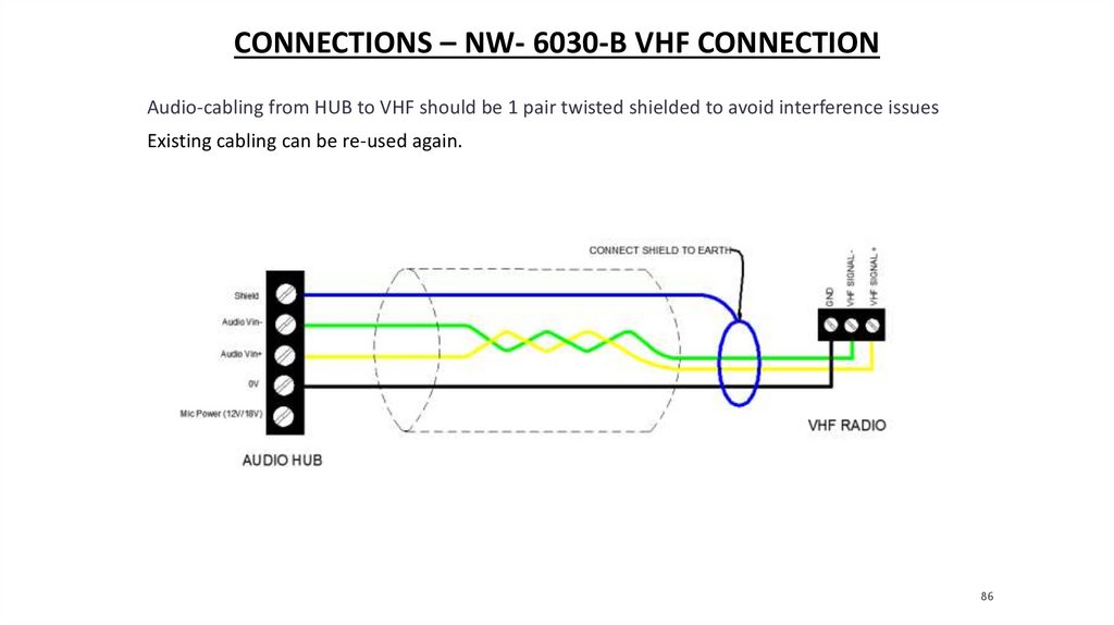
CONNECTIONS – NW- 6030-B VHF CONNECTIONAudio-cabling from HUB to VHF should be 1 pair twisted shielded to avoid interference issues
Existing cabling can be re-used again.
86
87.
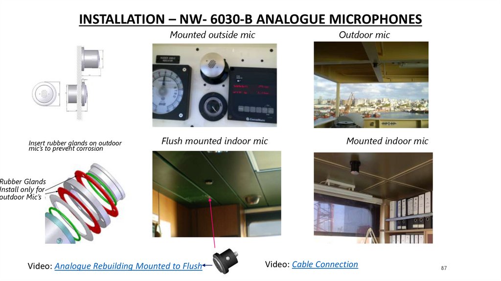
INSTALLATION – NW- 6030-B ANALOGUE MICROPHONESMounted outside mic
Insert rubber glands on outdoor
mic’s to prevent corrosion
Outdoor mic
Flush mounted indoor mic
Mounted indoor mic
Rubber Glands
Install only for
outdoor Mic’s
Video: Analogue Rebuilding Mounted to Flush
Video: Cable Connection
87
88.
QUESTIONS?88
89.
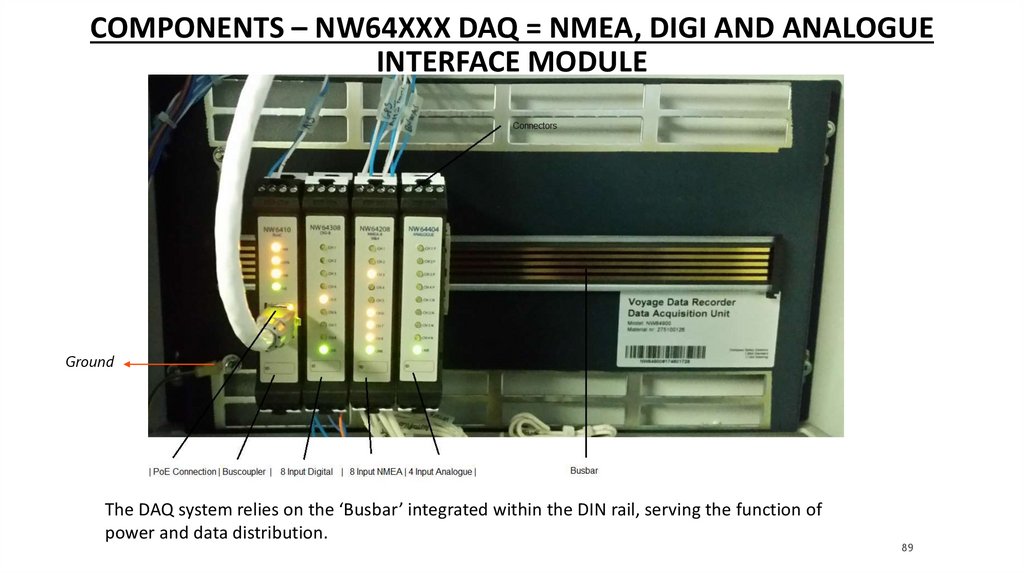
COMPONENTS – NW64XXX DAQ = NMEA, DIGI AND ANALOGUEINTERFACE MODULE
Ground
The DAQ system relies on the ‘Busbar’ integrated within the DIN rail, serving the function of
power and data distribution.
89
90.
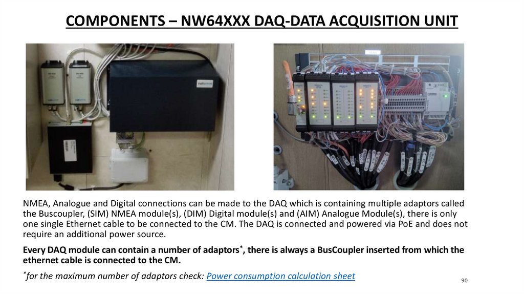
COMPONENTS – NW64XXX DAQ-DATA ACQUISITION UNITNMEA, Analogue and Digital connections can be made to the DAQ which is containing multiple adaptors called
the Buscoupler, (SIM) NMEA module(s), (DIM) Digital module(s) and (AIM) Analogue Module(s), there is only
one single Ethernet cable to be connected to the CM. The DAQ is connected and powered via PoE and does not
require an additional power source.
Every DAQ module can contain a number of adaptors*, there is always a BusCoupler inserted from which the
ethernet cable is connected to the CM.
*for
the maximum number of adaptors check: Power consumption calculation sheet
90
91.
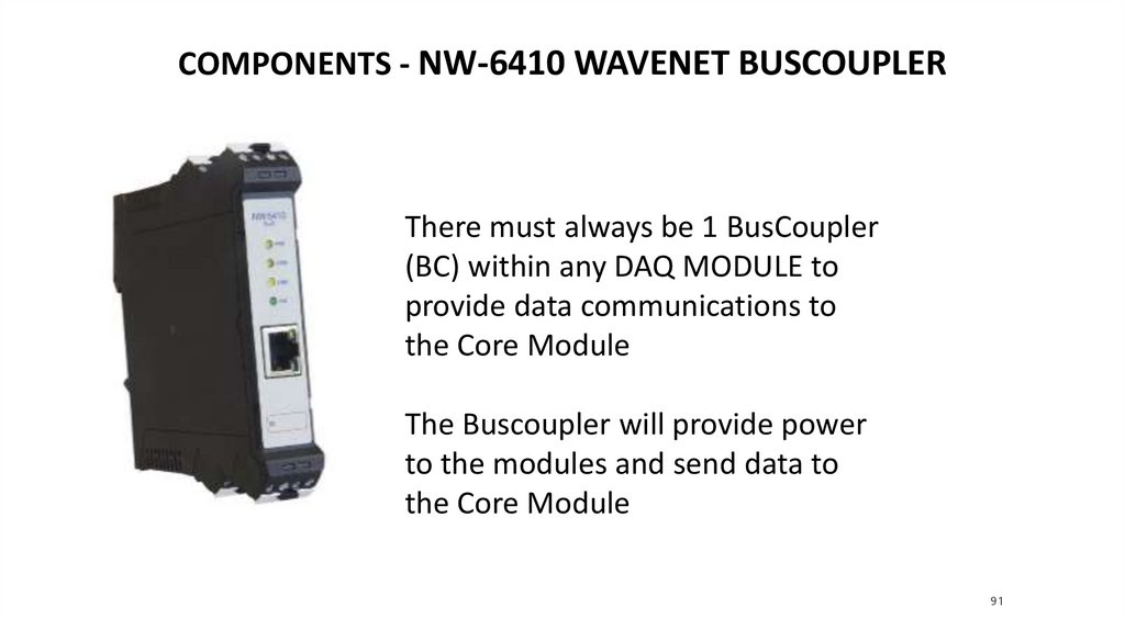
COMPONENTS - NW-6410 WAVENET BUSCOUPLERThere must always be 1 BusCoupler
(BC) within any DAQ MODULE to
provide data communications to
the Core Module
The Buscoupler will provide power
to the modules and send data to
the Core Module
91
92.
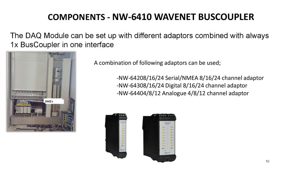
COMPONENTS - NW-6410 WAVENET BUSCOUPLERThe DAQ Module can be set up with different adaptors combined with always
1x BusCoupler in one interface
A combination of following adaptors can be used;
-NW-64208/16/24 Serial/NMEA 8/16/24 channel adaptor
-NW-64308/16/24 Digital 8/16/24 channel adaptor
-NW-64404/8/12 Analogue 4/8/12 channel adaptor
92
93.
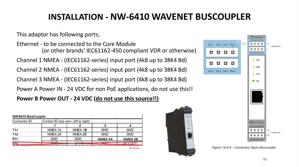
INSTALLATION - NW-6410 WAVENET BUSCOUPLERThis adaptor has following ports;
Ethernet - to be connected to the Core Module
(or other brands’ IEC61162-450 compliant VDR or otherwise)
Channel 1 NMEA - (IEC61162-series) input port (4k8 up to 38K4 Bd)
Channel 2 NMEA - (IEC61162-series) input port (4k8 up to 38K4 Bd)
Channel 3 NMEA - (IEC61162-series) input port (4k8 up to 38K4 Bd)
Power A Power IN - 24 VDC for non PoE applications, do not use this!!
Power B Power OUT - 24 VDC (do not use this source!!)
93
94.
INSTALLATION - NW-64XXX CONNECTOR AND WIRINGIDENTIFICATION IS AS FOLLOWS
Please note:
the largest width adaptor is shown with
connectors in columns A, B and C.
Smaller adaptors, with less channels, will
have 1 column (A) or 2 columns (A and B).
Top rows are identified by a T-prefix,
whereas the bottom rows have a B-prefix.
Terminal block rows are 1 on the front and 2
on the back.
e.g. TB2.2 is the top terminal of column B at
the back and is second from the left.
94
95.
INSTALLATION - NW-64XXX CONNECTOR AND WIRINGIDENTIFICATION IS AS FOLLOWS
Please note:
the largest width adaptor is shown with
connectors in columns A, B and C.
Smaller adaptors, with less channels, will
have 1 column (A) or 2 columns (A and B).
Top rows are identified by a T-prefix,
whereas the bottom rows have a B-prefix.
Terminal block rows are 1 on the front and 2
on the back.
e.g. TB2.2 is the top terminal of column B at
the back and is second from the left.
95
96.
INSTALLATION - NW-64XXX INPUT CHANNEL NUMBERINGPlease note:
LED’s from each individual
channel will be illuminated
when 24V is detected
(digital), serial data (NMEA
module, blinking) or analogue
activation (analogue module)
96
97.
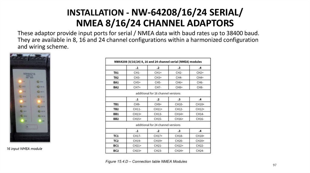
INSTALLATION - NW-64208/16/24 SERIAL/NMEA 8/16/24 CHANNEL ADAPTORS
These adaptor provide input ports for serial / NMEA data with baud rates up to 38400 baud.
They are available in 8, 16 and 24 channel configurations within a harmonized configuration
and wiring scheme.
16 input NMEA module
97
98.
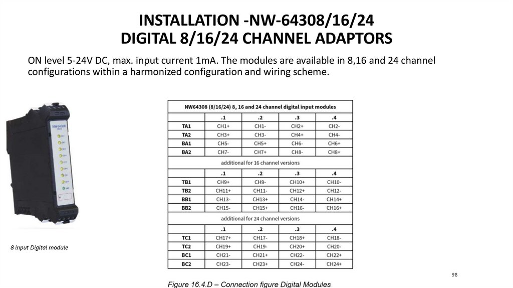
INSTALLATION -NW-64308/16/24DIGITAL 8/16/24 CHANNEL ADAPTORS
ON level 5-24V DC, max. input current 1mA. The modules are available in 8,16 and 24 channel
configurations within a harmonized configuration and wiring scheme.
8 input Digital module
98
99.
INSTALLATION -NW-64408 ANALOGUE 4-8-12 INPUTCHANNEL ADAPTOR
These adaptors send analogue data (-10V/10V or 0-20mA) they receive from their input ports into the Busbar
‘backplane’ for further processing by the Buscoupler, which streams the data onto the (VDR) network.
Analogue Adaptors(2x 4channel)
Depending upon which connector entry is chosen,
a choice is made between voltage and current measurement.
Video: Data Acquisition Module
99
100.
QUESTIONS?100
101.
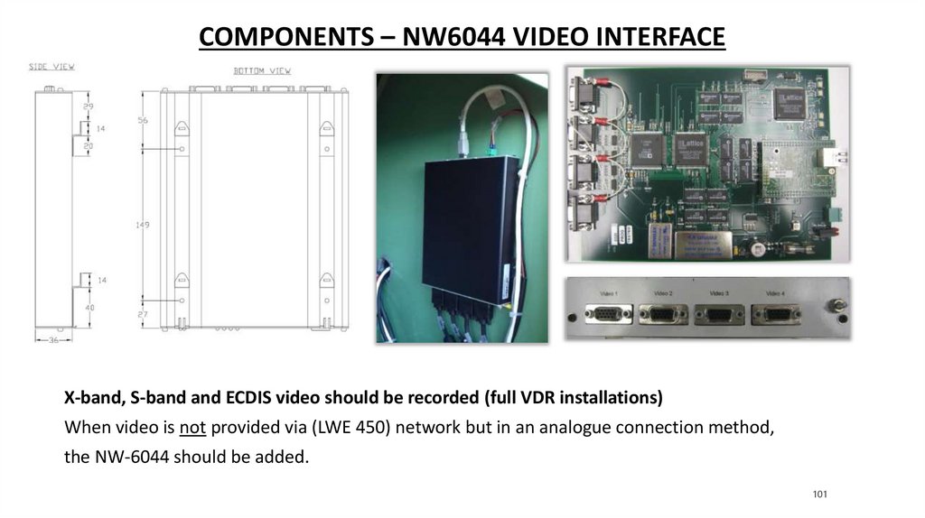
COMPONENTS – NW6044 VIDEO INTERFACEX-band, S-band and ECDIS video should be recorded (full VDR installations)
When video is not provided via (LWE 450) network but in an analogue connection method,
the NW-6044 should be added.
101
102.
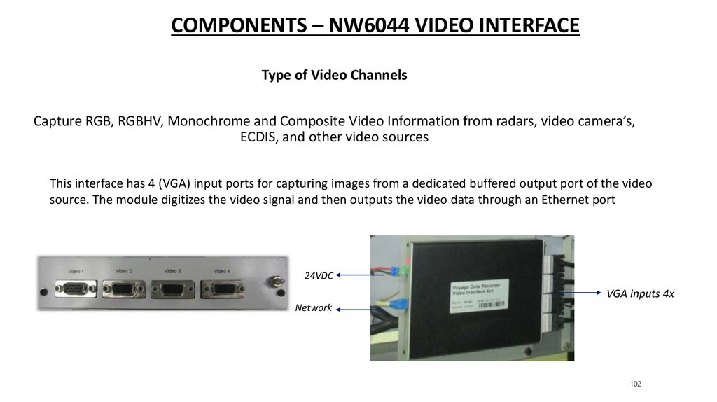
COMPONENTS – NW6044 VIDEO INTERFACEType of Video Channels
Capture RGB, RGBHV, Monochrome and Composite Video Information from radars, video camera’s,
ECDIS, and other video sources
This interface has 4 (VGA) input ports for capturing images from a dedicated buffered output port of the video
source. The module digitizes the video signal and then outputs the video data through an Ethernet port
24VDC
VGA inputs 4x
Network
102
103.
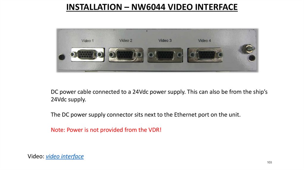
INSTALLATION – NW6044 VIDEO INTERFACEDC power cable connected to a 24Vdc power supply. This can also be from the ship’s
24Vdc supply.
The DC power supply connector sits next to the Ethernet port on the unit.
Note: Power is not provided from the VDR!
Video: video interface
103
104.
QUESTIONS?104
105.
NW6000 TRAINING105