 ecology
 industry
Similar presentations:


Sedimentation tank
1.
SEDIMENTATIONTANK
Abdul Haqi Ibrahim, PhD
Water Research Group (WAREG)
School of Environmental Engineering
Universiti Malaysia Perlis.
2.
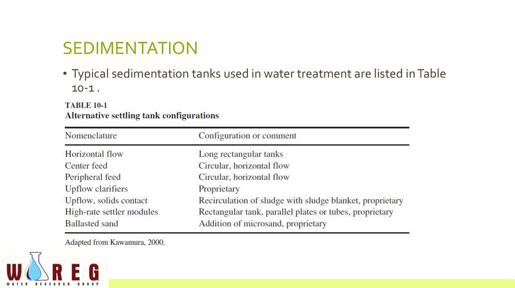
SEDIMENTATION• Typical sedimentation tanks used in water treatment are listed in Table
10-1 .
3.
• preference for settling coagulation/flocculation floc is• (1) a rectangular tank containing high-rate settler modules,
• (2) a long rectangular tank, and
• (3) a high-speed microsand clarifier
4.
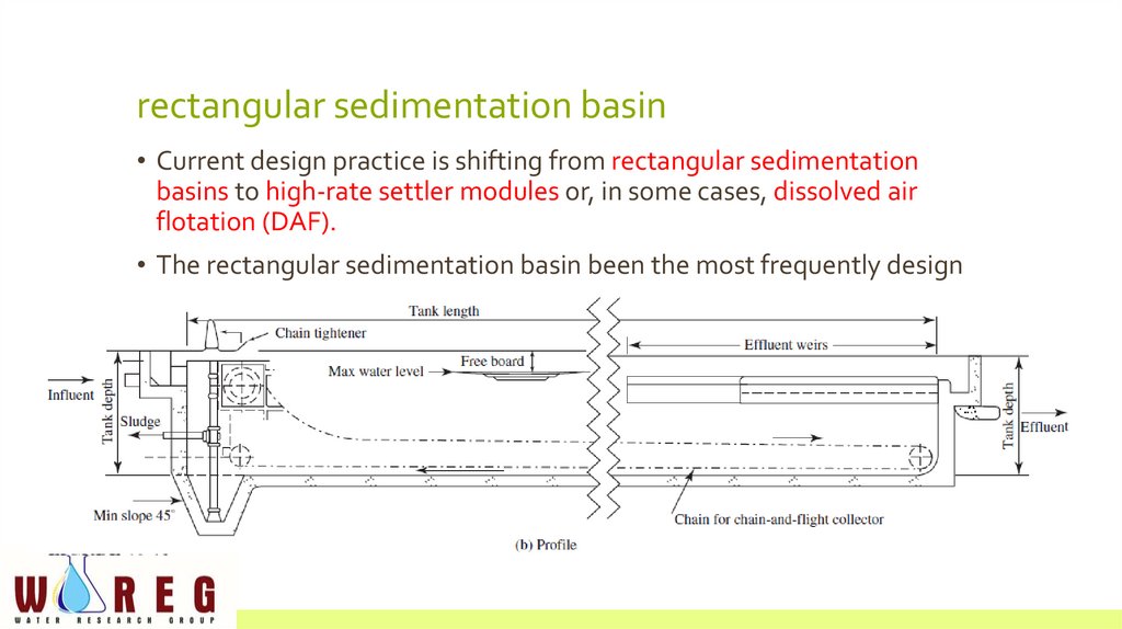
rectangular sedimentation basin• Current design practice is shifting from rectangular sedimentation
basins to high-rate settler modules or, in some cases, dissolved air
flotation (DAF).
• The rectangular sedimentation basin been the most frequently design
5.
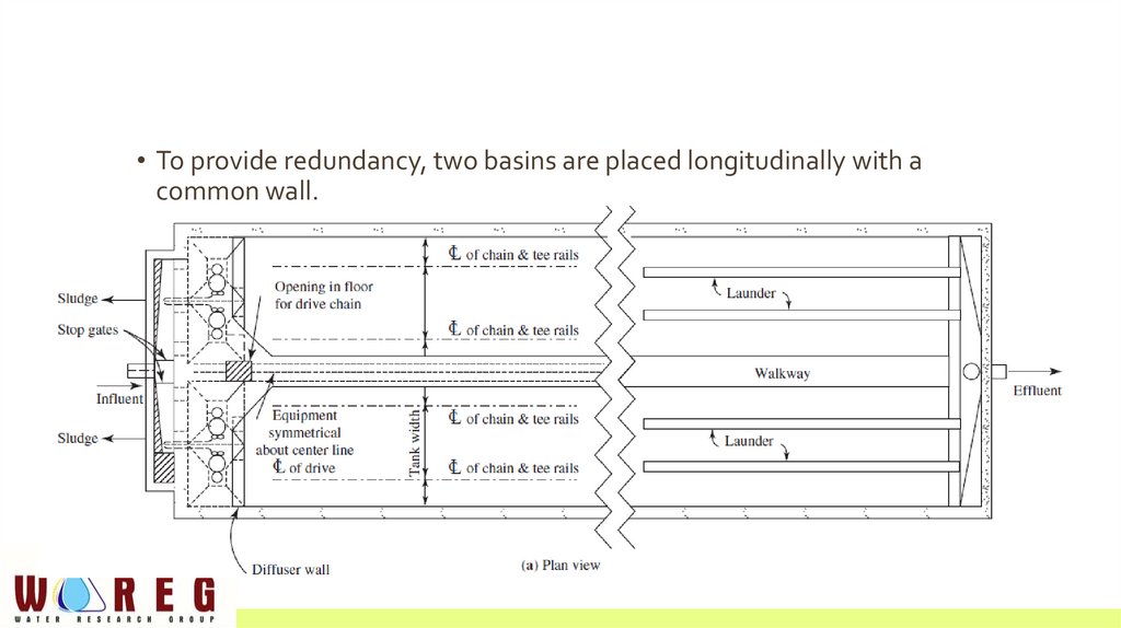
• To provide redundancy, two basins are placed longitudinally with acommon wall.
6.
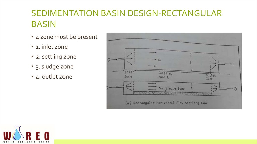
SEDIMENTATION BASIN DESIGN-RECTANGULARBASIN
• 4 zone must be present
• 1. inlet zone
• 2. settling zone
• 3. sludge zone
• 4. outlet zone
7.
INLET ZONE• preferred arrangement is a direct connection between the flocculation
basin and the settling tank.
• Disperse influent flow and suspended matter uniformly over the cross
section of the basin
• When the flocculated water must be piped to the settling tank, the flow
velocity commonly used is in the range of 0.15 to 0.6 m/s.
• This velocity must be reduced and the flow spread evenly over the cross
section of the settling tank.
• A diffuser wall is the most effective way to accomplish this.
8.
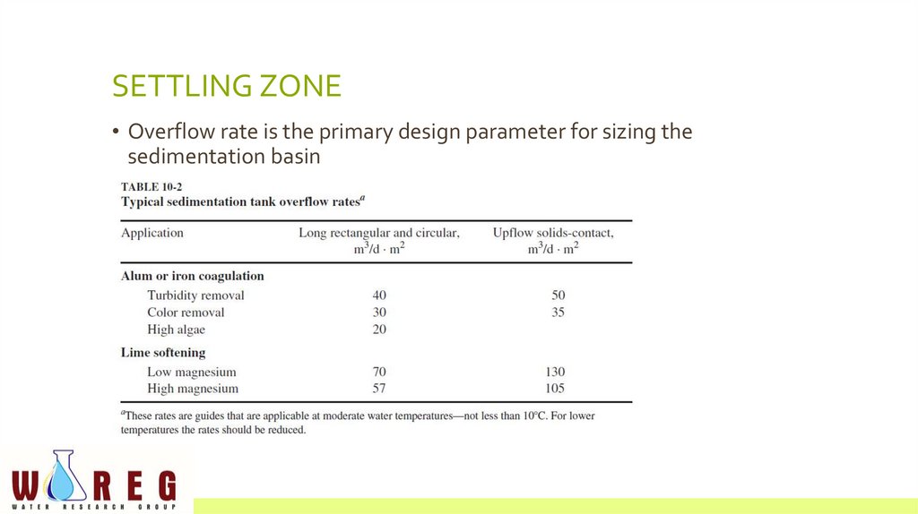
SETTLING ZONE• Overflow rate is the primary design parameter for sizing the
sedimentation basin
9.
• These rates are usually conservative enough that the inlet zone doesnot have to be added to the length calculated for the settling zone
• In theory the sedimentation basin depth [also called side water depth
(SWD)] should not be a design parameter because removal efficiency is
based on overflow rate.
• However, there is a practical minimum depth required for sludge
removal equipment
• Open sedimentation tanks greater than 30 m in length are especially
susceptible to wind effects
• For longer tanks, wave breakers (launders or baffles) placed at 30 m
intervals are recommended
10.
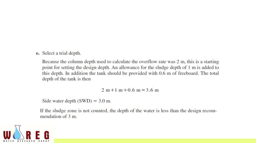
• The tank depth is usually increased by about 0.6 m to provide freeboardto act as a wind barrier.
• Horizontal flow velocities must be controlled to avoid undue
turbulence, back mixing, and scour of particles from the sludge.
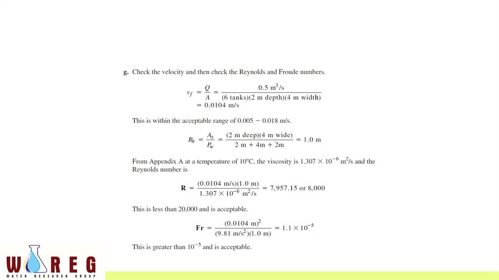
• Reynolds and Froude numbers can be used to check on turbulence and
back mixing.
11.
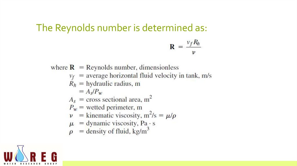
The Reynolds number is determined as:12.
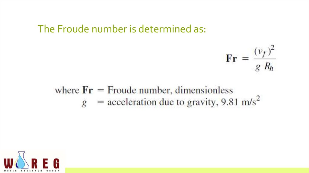
The Froude number is determined as:13.
• Recommended values for the settling zone design are R < 20,000 and Fr> 10 -5
• large Reynolds number indicates a high degree of turbulence
• A low Froude number indicates that water flow is not dominated by
horizontal flow, and back mixing may occur.
14.
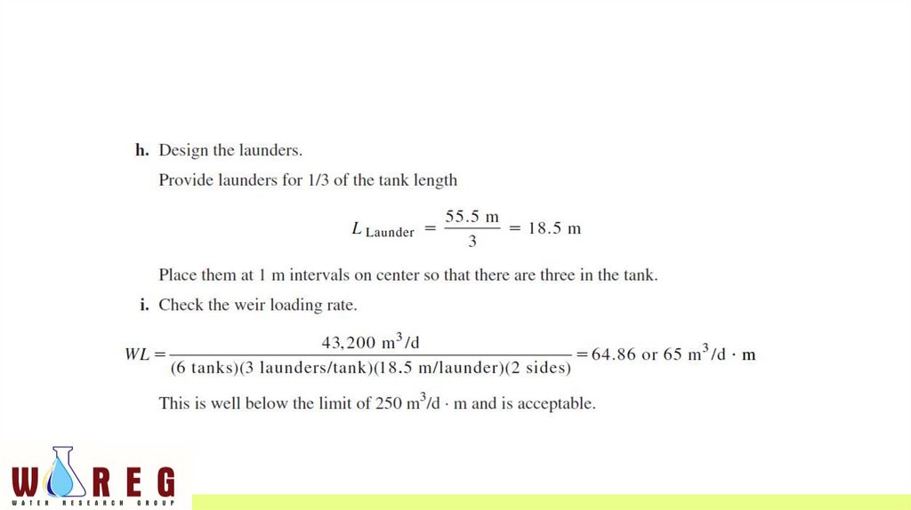
OUTLET ZONE• The outlet zone is composed of launders running parallel to the length
of the tank
• The weirs should cover at least one-third, and preferably up to one-half,
the basin length
• The water level in the tank is controlled by the end wall or overflow
weirs.
15.
SLUDGE ZONE• In selecting the depth of the sedimentation tank, an allowance of
between 0.6 and 1 m is made for sludge accumulation and sludge
removal equipment.
• To facilitate sludge removal, the bottom of the tank is sloped toward a
sludge hopper at the head end of the tank
• When mechanical equipment is used, the slope should be at least 1:600
16.
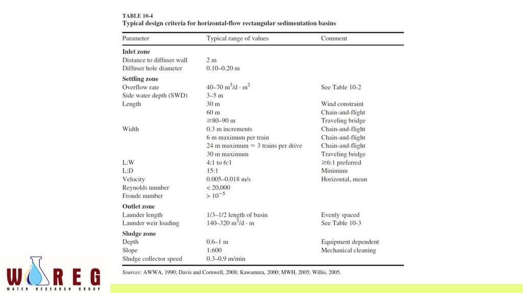
• Typical design criteria for horizontal-flow rectangular sedimentationbasins in larger water treatment plants (40,000 m3 /d) are summarized
in Table 10-4 .
• Some design criteria are quite rigid while others only provide guidance.
17.
18.
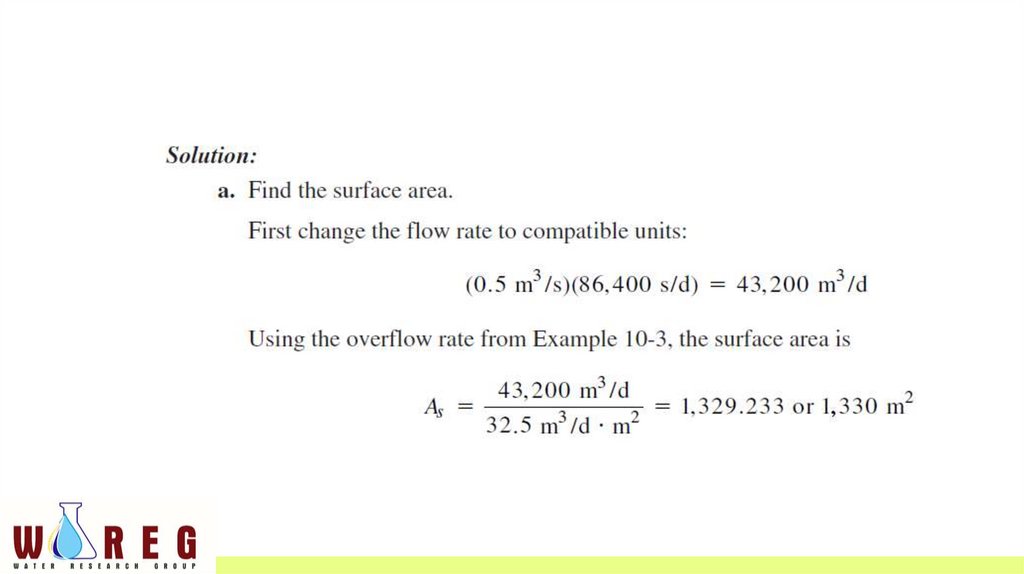
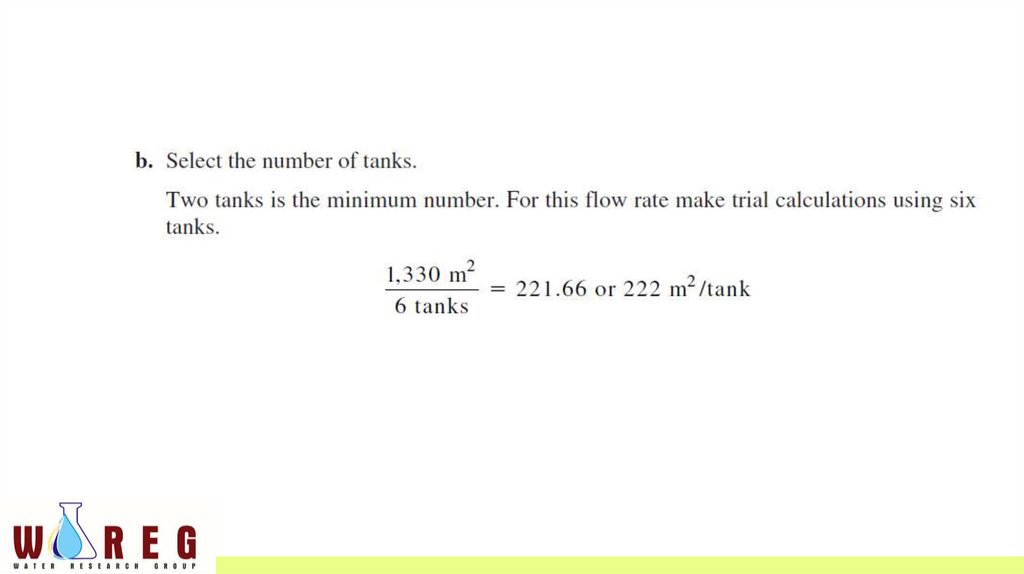
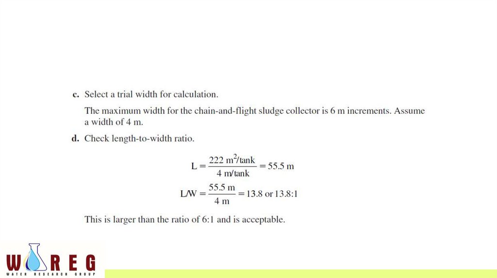
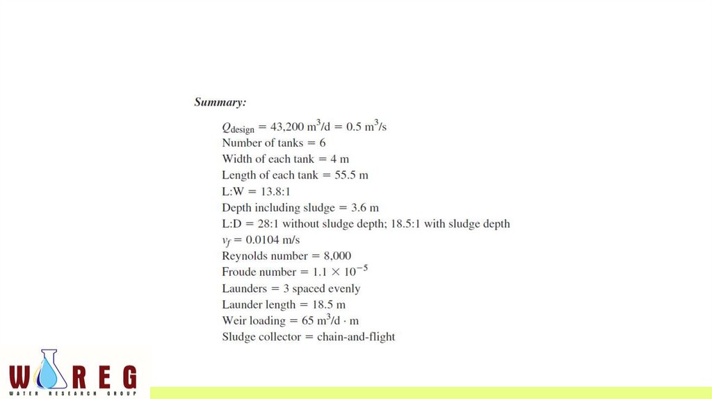
EXAMPLE• Design the settling tank(s) for the city of Stillwater’s water treatment
plant expansion using the design overflow rate found in Example 10-3 .
The maximum day design flow is 0.5 m 3 /s. Assume a water
temperature of 10 C.
19.
20.
21.
22.
23.
24.
25.
26.
27.
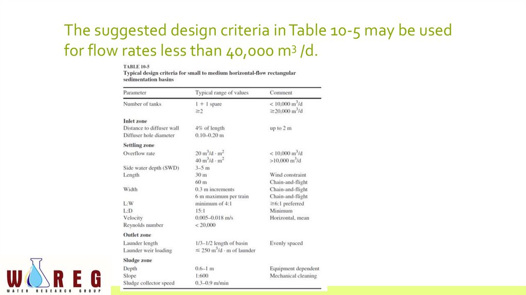
The suggested design criteria in Table 10-5 may be usedfor flow rates less than 40,000 m3 /d.
28.
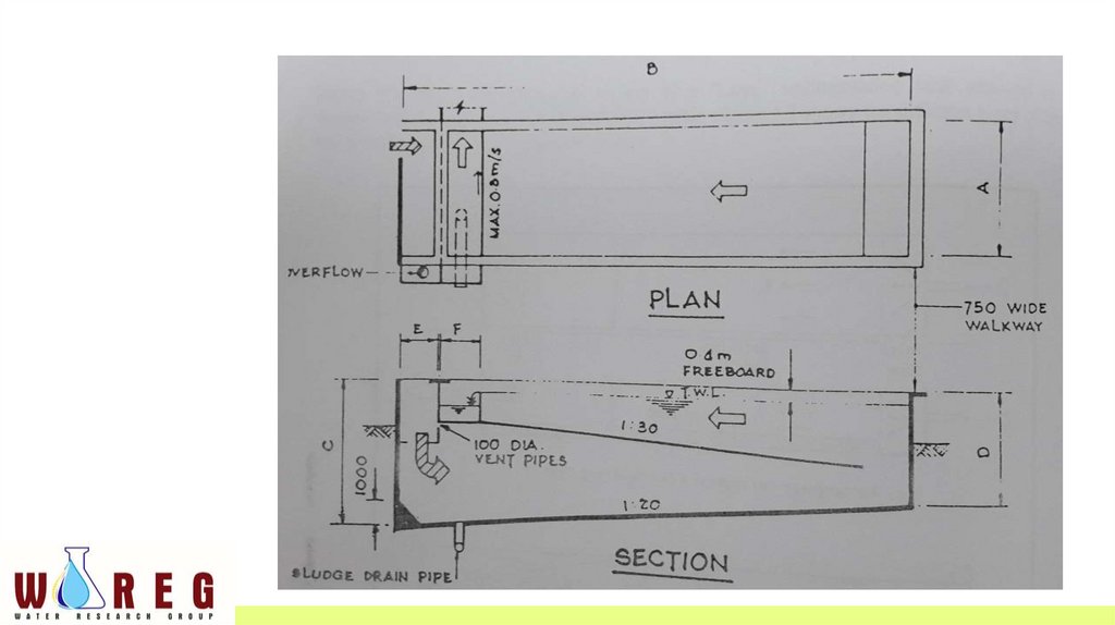
“LOVO TANK”• Modification of rectangular horizontal flow sedimentation tank
• Incorporating an intermediate slanting slab spanning the whole width
of the tank
• Thus dividing it into a top and a bottom compartment.
29.
30.
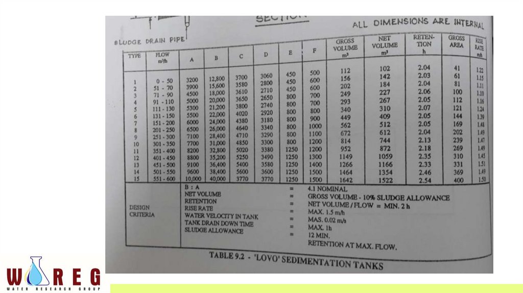
Design criteria for “LOVO” sedimentation tank• Surface loading @ overflow rate should not exceed 1.5 m3/m2/hr
• Detention time must not be less than 2 hrs
• L:W is between 2:1 and 4:1
• Depth between 3 to 5 m
• A certain quantity of sludge acculumation (10 to 15 % of tank capacity)
should be allowed for in computing the capacity of the tank.
• Inlet velocity should be in the region of 0.1 m/sec and outlet weir
loading should be about 8m3/hr/m