


 marketing
 mechanics
Similar presentations:


Amkodor Forwarder Proposal v.2.1
1.
Amkodor Forwarder Proposal v.2.12.
23.
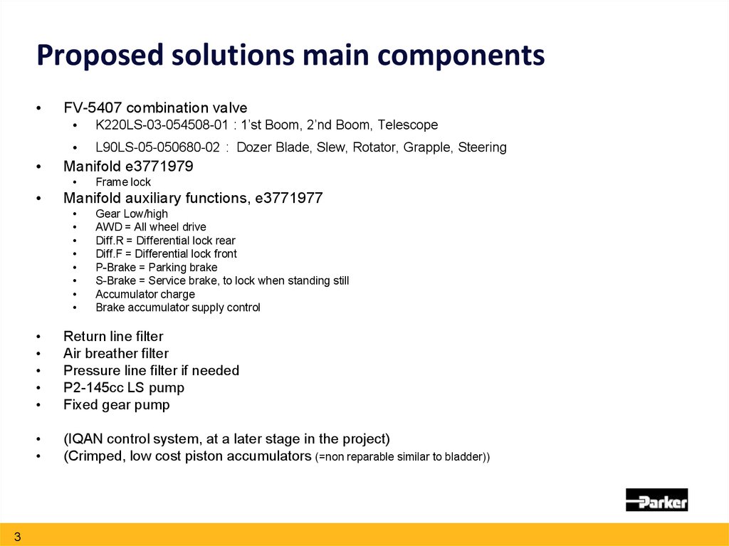
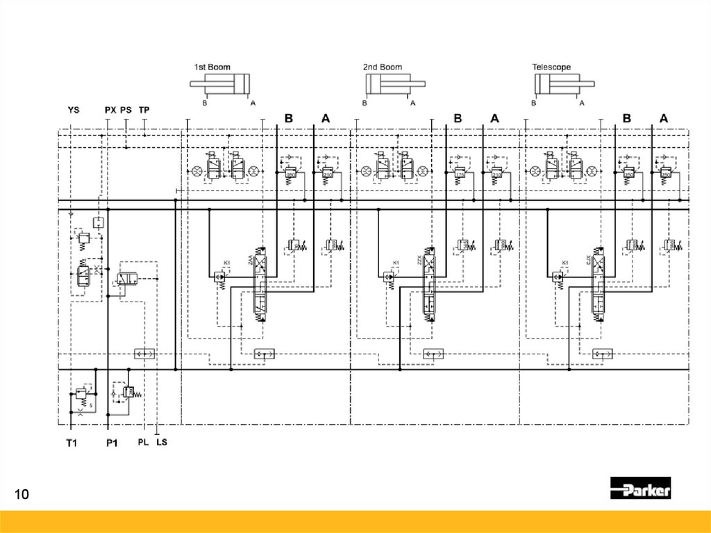
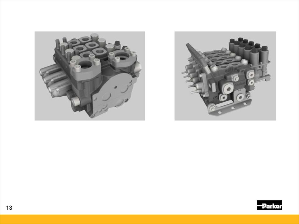
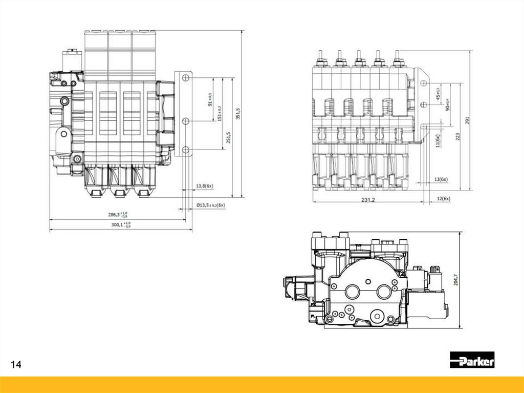
Proposed solutions main componentsFV-5407 combination valve
K220LS-03-054508-01 : 1’st Boom, 2’nd Boom, Telescope
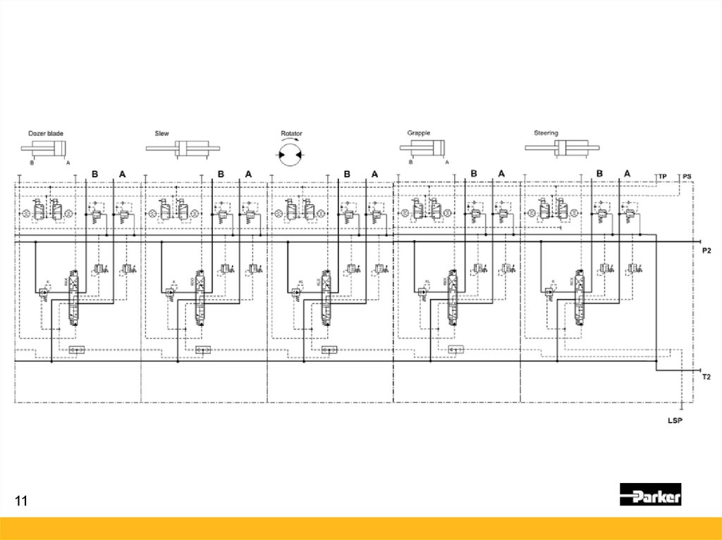
L90LS-05-050680-02 : Dozer Blade, Slew, Rotator, Grapple, Steering
Manifold e3771979
Manifold auxiliary functions, e3771977
3
Frame lock
Gear Low/high
AWD = All wheel drive
Diff.R = Differential lock rear
Diff.F = Differential lock front
P-Brake = Parking brake
S-Brake = Service brake, to lock when standing still
Accumulator charge
Brake accumulator supply control
Return line filter
Air breather filter
Pressure line filter if needed
P2-145cc LS pump
Fixed gear pump
(IQAN control system, at a later stage in the project)
(Crimped, low cost piston accumulators (=non reparable similar to bladder))
4.
Mid Inlet - Copy Spool, Tank Counter Pressure4
5.
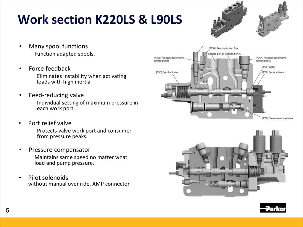
Work section K220LS & L90LSMany spool functions
Function adapted spools.
Force feedback
Eliminates instability when activating
loads with high inertia
Feed-reducing valve
Individual setting of maximum pressure in
each work port.
Port relief valve
Protects valve work port and consumer
from pressure peaks.
Pressure compensator
Maintains same speed no matter what
load and pump pressure.
5
Pilot solenoids
without manual over ride, AMP connector
6.
Crane valve – K220LS / L90LS1st Boom
Single acting spool on to save energy and improve simultaneous operation by
reducing needed pump flow.
Pressure feedback to give outstanding controllability with acceleration control.
2nd Boom and Telescope
Regenerative spools to improve simultaneous operation by reducing required
pump flow (enables other functions to run faster).
Telescope – verify that the port relief and LS limiting pressures are correct.
6
7.
L90LS Dozer Blade• Consider using a load holding valve.
• L90LS D-spool, work port relief 230 bar, 30cSt, 50 degC
nominal leakage:
25 cm^3/min @ 100 bar
45 cm^3/min @ 200 bar
7
8.
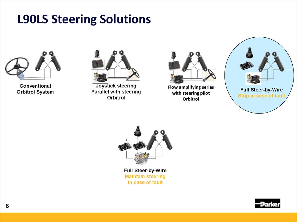
L90LS Steering SolutionsConventional
Orbitrol System
Joystick steering
Parallel with steering
Orbitrol
Full Steer-by-Wire
Maintain steering
in case of fault
8
Flow amplifying series
with steering pilot
Orbitrol
Full Steer-by-Wire
Stop in case of fault
9.
Steering• A standard L90 work section in this proposal.
Consider using additional equipment to fullfil high
enough level of safety.
• Parker has launched the SBW110 valve that
facilitates fulfilment of
ISO11850 Machinery for Forestry,
ISO5010 Wheeled Machines-Steering
9
10.
1011.
1112.
1213.
1314.
1415.
Pilot Pressure BlockingInlet section specified for external
loop of the pilot pressure
Cartridge
DSH083B
Coil
CCP024A
Body
B08-3 6B
15
16.
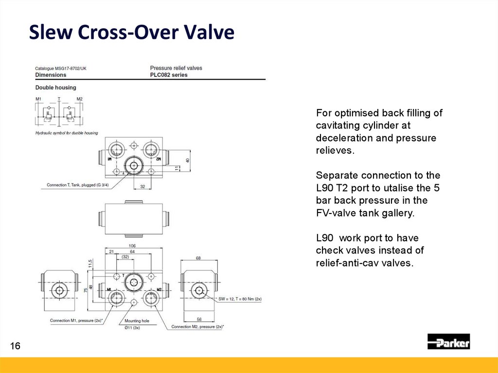
Slew Cross-Over ValveFor optimised back filling of
cavitating cylinder at
deceleration and pressure
relieves.
Separate connection to the
L90 T2 port to utalise the 5
bar back pressure in the
FV-valve tank gallery.
L90 work port to have
check valves instead of
relief-anti-cav valves.
16
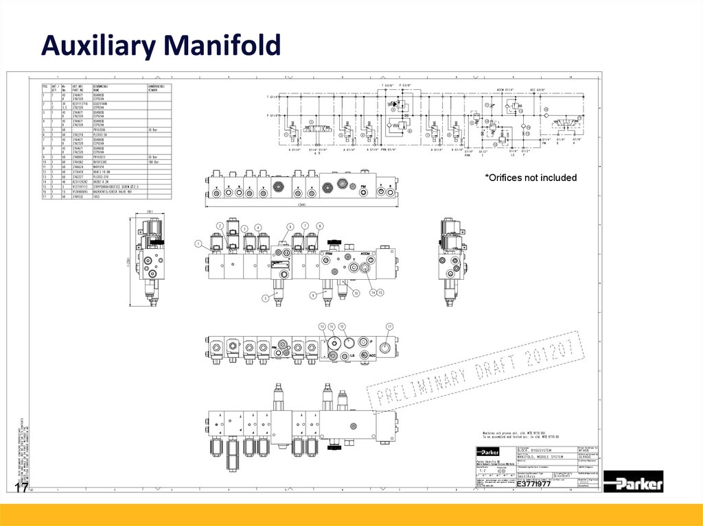
17.
Auxiliary Manifold*Orifices not included
17
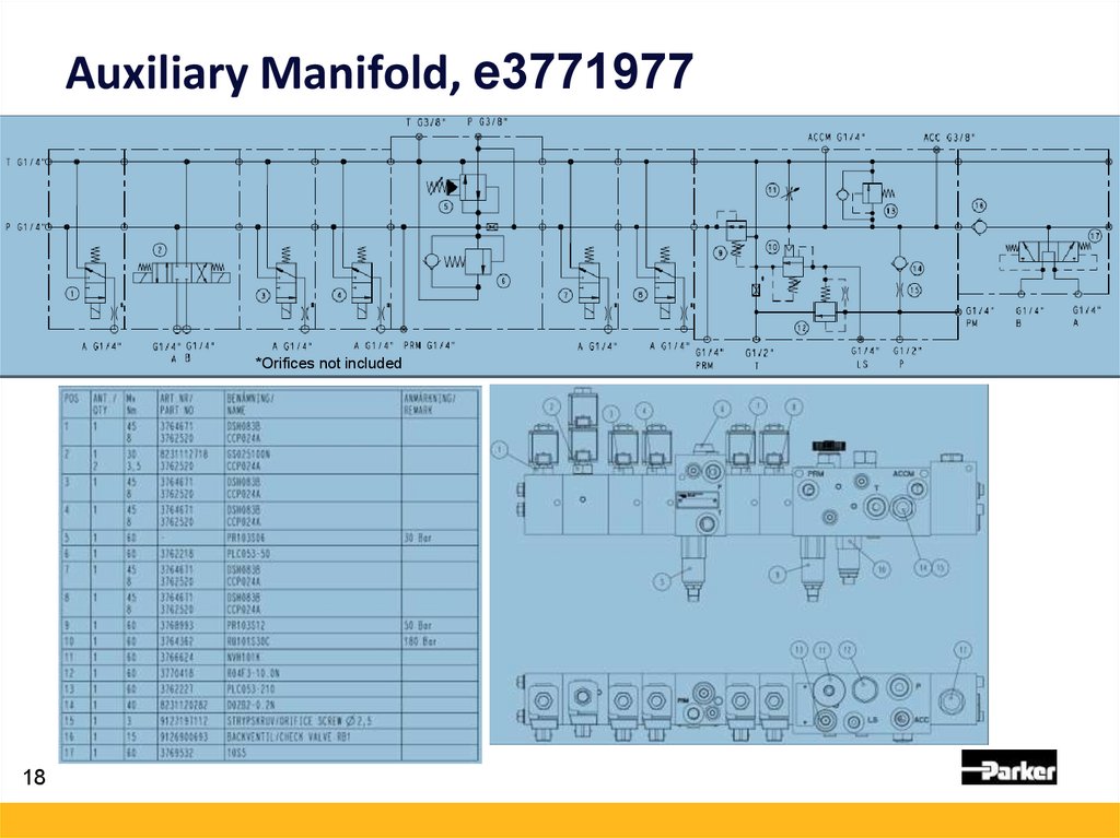
18.
Auxiliary Manifold, e3771977*Orifices not included
18
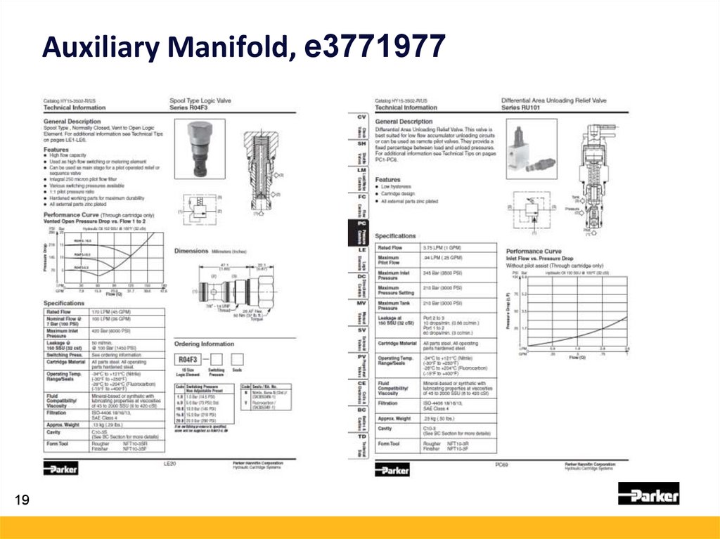
19.
Auxiliary Manifold, e377197719
20.
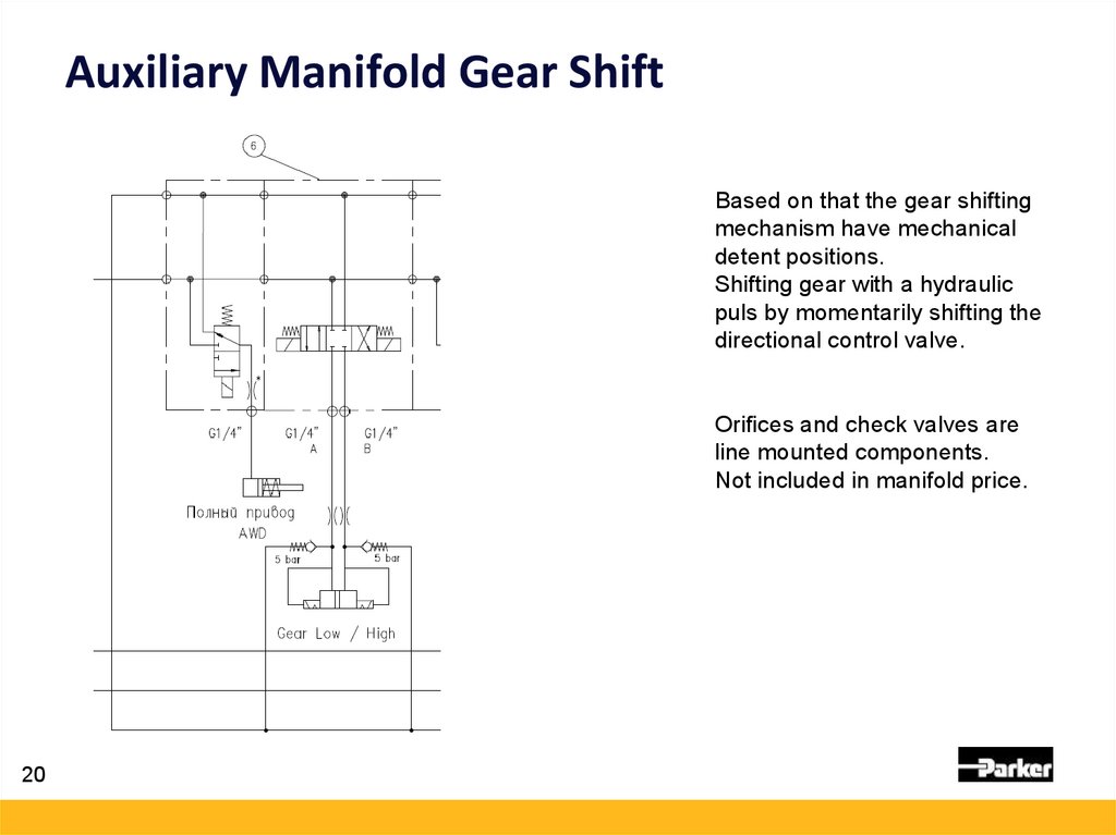
Auxiliary Manifold Gear ShiftBased on that the gear shifting
mechanism have mechanical
detent positions.
Shifting gear with a hydraulic
puls by momentarily shifting the
directional control valve.
Orifices and check valves are
line mounted components.
Not included in manifold price.
20
21.
Auxiliary Manifold AlternativeSupplied by the LS pump
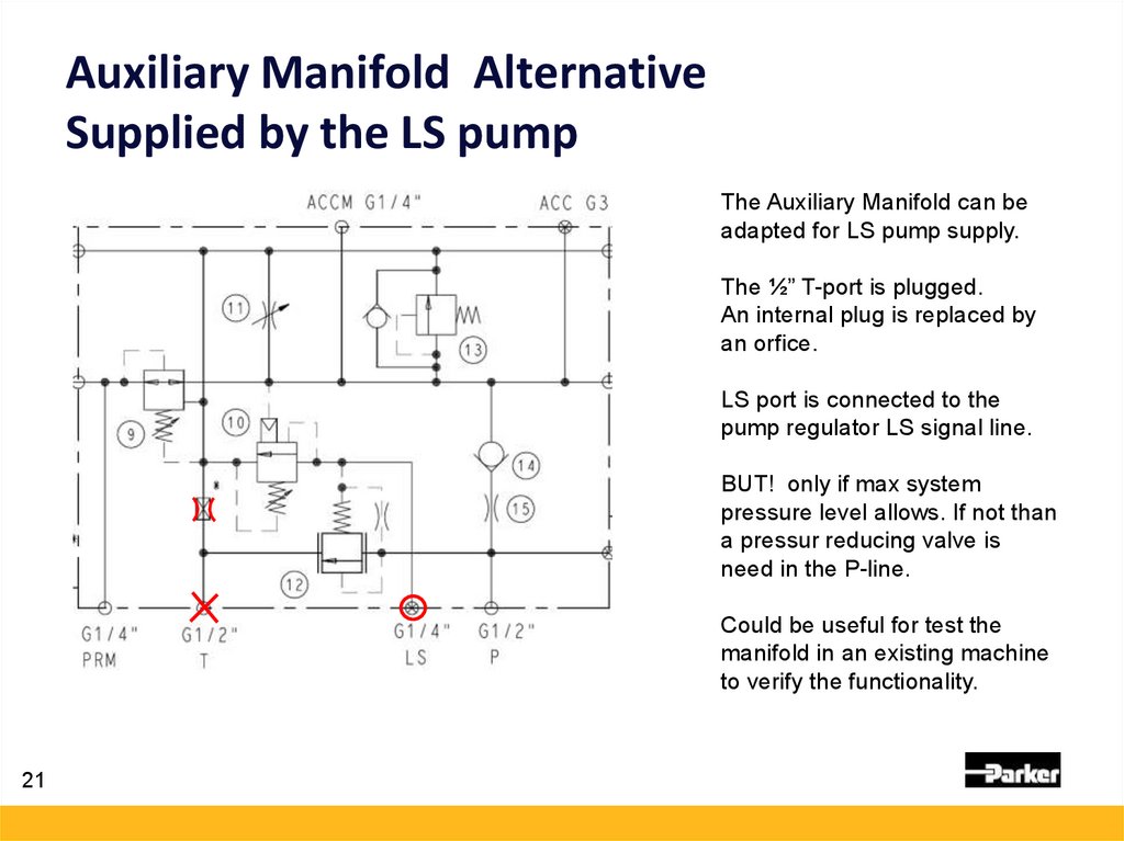
The Auxiliary Manifold can be
adapted for LS pump supply.
The ½” T-port is plugged.
An internal plug is replaced by
an orfice.
LS port is connected to the
pump regulator LS signal line.
BUT! only if max system
pressure level allows. If not than
a pressur reducing valve is
need in the P-line.
Could be useful for test the
manifold in an existing machine
to verify the functionality.
21
22.
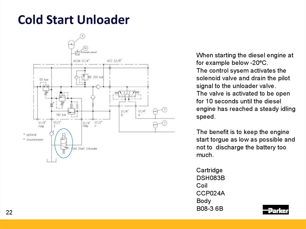
Cold Start UnloaderWhen starting the diesel engine at
for example below -20ºC.
The control sysem activates the
solenoid valve and drain the pilot
signal to the unloader valve.
The valve is activated to be open
for 10 seconds until the diesel
engine has reached a steady idling
speed.
The benefit is to keep the engine
start torgue as low as possible and
not to discharge the battery too
much.
22
Cartridge
DSH083B
Coil
CCP024A
Body
B08-3 6B
23.
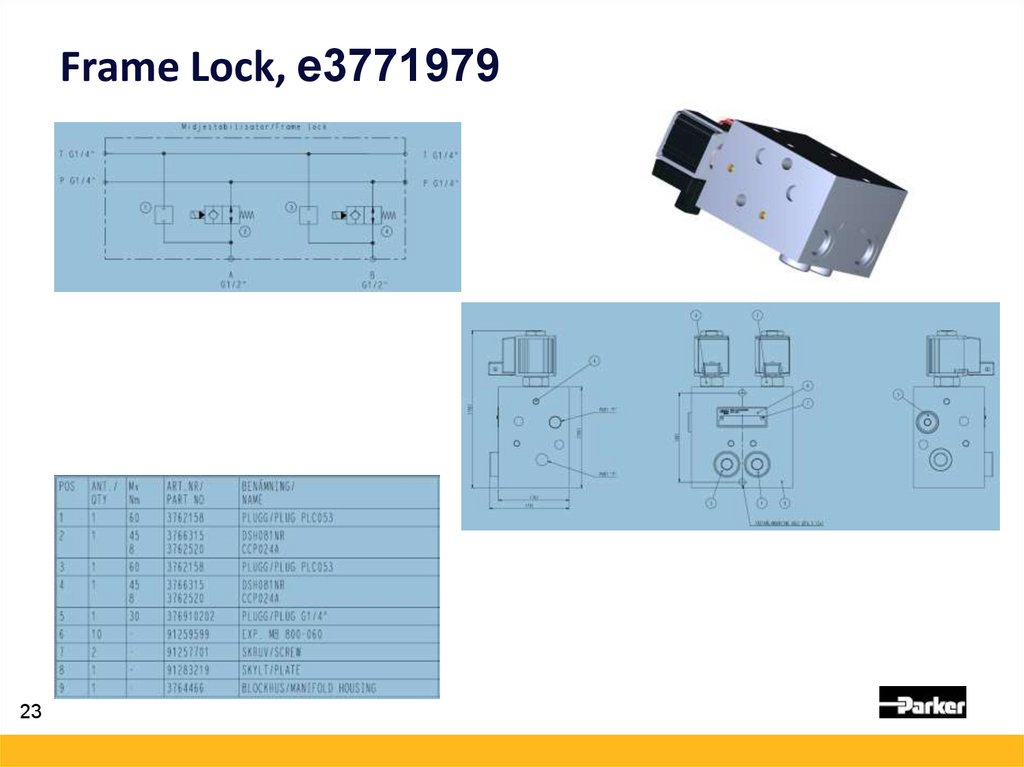
Frame Lock, e377197923
24.
Frame LockDynamic
pressure peaks ?
24
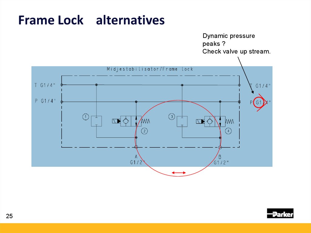
25.
Frame Lock alternativesDynamic pressure
peaks ?
Check valve up stream.
25
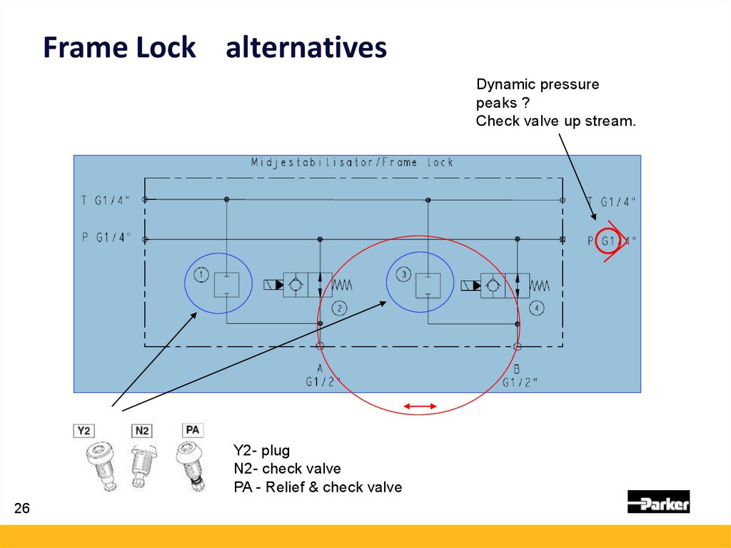
26.
Frame Lock alternativesDynamic pressure
peaks ?
Check valve up stream.
Y2- plug
N2- check valve
PA - Relief & check valve
26
27.
Return Line Filter,Filter selection parameters
Estimated return oil flow at simultaneous operation, Example:
Slew 65 Lpm
1st Boom Lift 60 Lpm
2nd boom lift 70 Lpm
Tele In 70 Lpm
+aux manifold 20Lpm
Say total about ~ 350 Lpm
Operating Limitations due to temperature and viscosity:
• 50 Lpm @ viscosity 1000 cSt
• 350 Lpm @ viscosity 125 - 15 cSt
27
Select cleanliness target typically 18/16/13 ISO4406 - usually matches 10 micron Beta200
By-pass valve 1,7 bar
Initial pressure drop ratio relationship 1/3 of the By-pass -> target dp of about ~ 0,5 bar
Double the element size to get 3 times as much life expectancy on the element.
Say dp ~0,25 bar @ 350 Lpm
28.
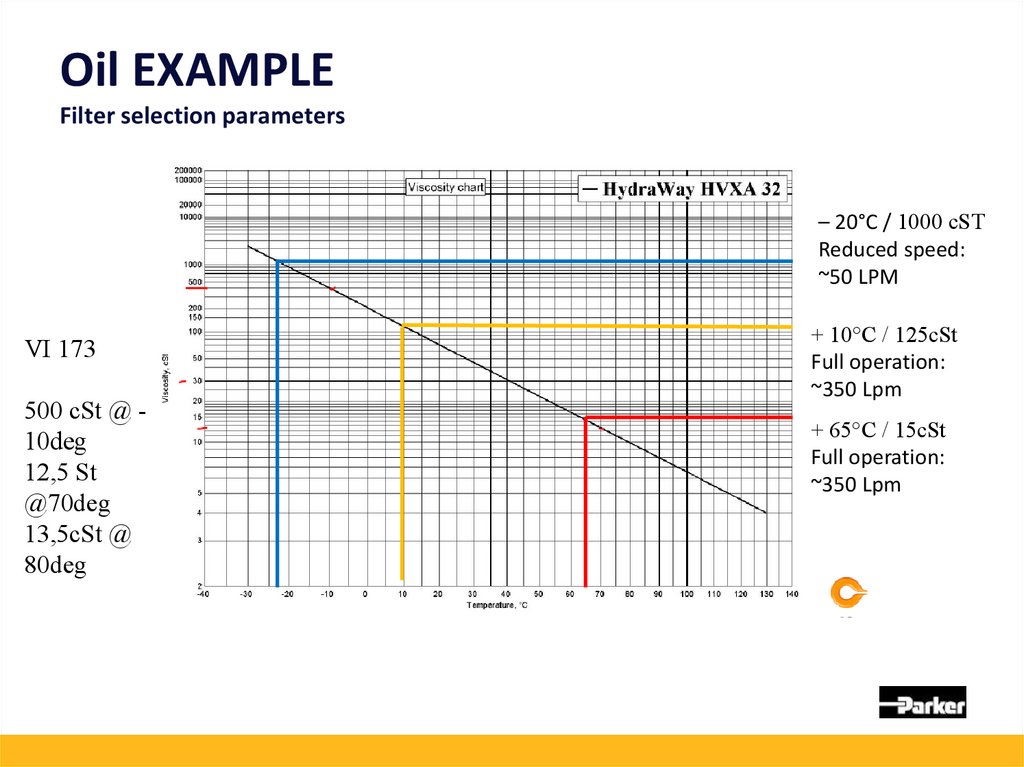
Oil EXAMPLEFilter selection parameters
– 20°C / 1000 cST
Reduced speed:
~50 LPM
VI 173
500 cSt @ 10deg
12,5 St
@70deg
13,5cSt @
80deg
+ 10°C / 125cSt
Full operation:
~350 Lpm
+ 65°C / 15cSt
Full operation:
~350 Lpm
29.
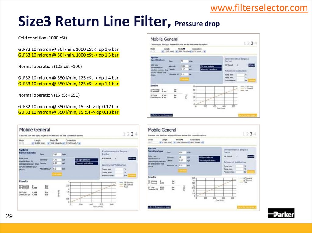
www.filterselector.comSize3 Return Line Filter, Pressure drop
Cold condition (1000 cSt)
GLF32 10 micron @ 50 l/min, 1000 cSt -> dp 1,6 bar
GLF33 10 micron @ 50 l/min, 1000 cSt -> dp 1,3 bar
Normal operation (125 cSt +10C)
GLF32 10 micron @ 350 l/min, 125 cSt -> dp 1,4 bar
GLF33 10 micron @ 350 l/min, 125 cSt -> dp 1,1 bar
Normal operation (15 cSt +65C)
GLF32 10 micron @ 350 l/min, 15 cSt -> dp 0,17 bar
GLF33 10 micron @ 350 l/min, 15 cSt -> dp 0,13 bar
29
30.
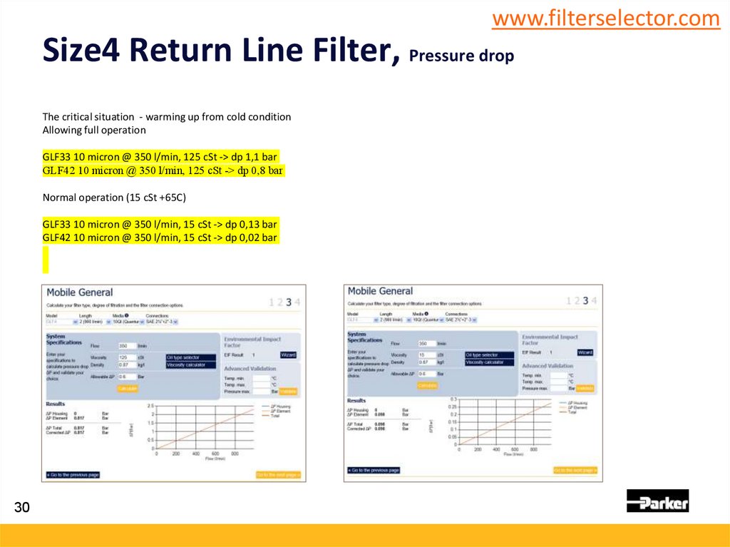
www.filterselector.comSize4 Return Line Filter, Pressure drop
The critical situation - warming up from cold condition
Allowing full operation
GLF33 10 micron @ 350 l/min, 125 cSt -> dp 1,1 bar
GLF42 10 micron @ 350 l/min, 125 cSt -> dp 0,8 bar
Normal operation (15 cSt +65C)
GLF33 10 micron @ 350 l/min, 15 cSt -> dp 0,13 bar
GLF42 10 micron @ 350 l/min, 15 cSt -> dp 0,02 bar
30
31.
3132.
3233.
Return Line Filter,Filter selection
Filter configuration:
• GLF4 Length2, ( alternatively GLF3 Length3)
• Funnel
• Magnet column
• Filling port
• GLI version instead of GLF ?
• Further options to be discussed with the customer..
33
..