


")


 internet
Similar presentations:


Microcontrollers misis 2017. Applications
1. INTRODUCTION TO THE WORLD OF MICROCONTROLLERS
Lecture 1MICROCONTROLLERS
MISiS 2017
2. Applications
3. Microcontroller ≠ Microprocessor
Microcontroller =CPU + ADC + RAM +
ROM + OSC + DAC +
EEPROM + SPI + I2C +
UART + Vregulator
4. NUMBERS
5. Operators Gate
AND GateBinary multiplication
OR GATE
Binary addition
NOT GATE EXCLUSIVE OR
Binary inverted
EXCLUSIVE OR
6. Operators C++
Symbol FunctionSymbol
Function
++
+1
<<
a shift to the left
--
-1
>>
a shift to the right
~
Binary inverted
<
less
-
Arithmetical minus
>
more
+
Arithmetical plus
%
&
Binary multiplication
the remainder of the
division
&&
Logical and
|
Binary addition
||
Logical or
==
same
=
assignment
!=
Not same
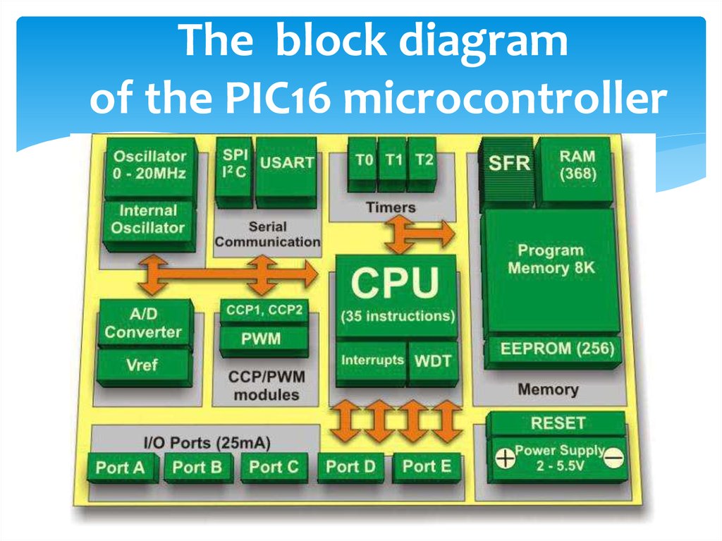
7.
The block diagramof the PIC16 microcontroller
8. HARVARD ARCHITECTURE
9. Pin numbers PIC16F877and functions
10. OSCILLATOR
11. Watch Dog Timer
12. A/D CONVERTER (12bit)
13. Hardware and firmware
14. Example 1
Read port and write port (GPIO) LEDs and buttonsSteps
Looking for MK, read PDF.
Make up the schematic circuit diagram
Do the device under the scheme
Draw the block diagram of the program
Write the code on the block diagram
Programmable
15. Make up the schematic circuit diagram
16. Do the device under the scheme
17. Draw the block diagram of the program
STARTINITIALISATIONS
IF RA1==1
YES
RB0=1; // LED on
NO
RB0=0; // LED off
18. Write the code on the block diagram
#include <pic.h> // plug-in headers (libraries and files)__CONFIG(0x03F72); // configurable MK
void main(void) //Start program
{
TRISА<1>=1; // select bit port input
// оr so: TRISA=0b111111;
//выход-0 вход-1
TRISB=0; //select bit port output
PORTB=0; //source data entry in the registers of the port
// оr so: RB0 = 0; // source data entry in the registers of the port
while(1) // infinite loop
{
if (RA1==1)
RB0=1;
//Yes
else RB0=0; //No
}
}