


 biology
BC-5000/5150series Service Training Hematology Global Technical Support Department
1.
BC-5000/5150series Service TrainingHematology Global Technical Support Department
Version V2.0
No
© 2018 Mindray Confidential
2.
ContentClinical
Overview
Principal
Installation
Software
Hardware
Optical system
Liquid system
Mechanical structure
2
© 2018 Mindray Confidential
3.
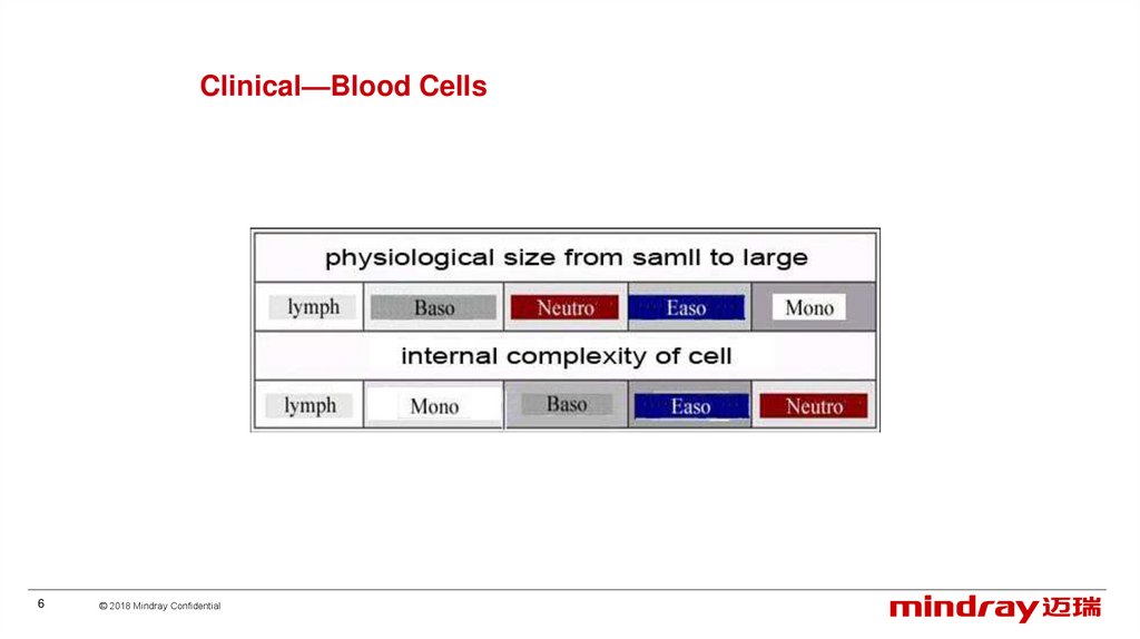
Clinical—Blood Cells3
© 2018 Mindray Confidential
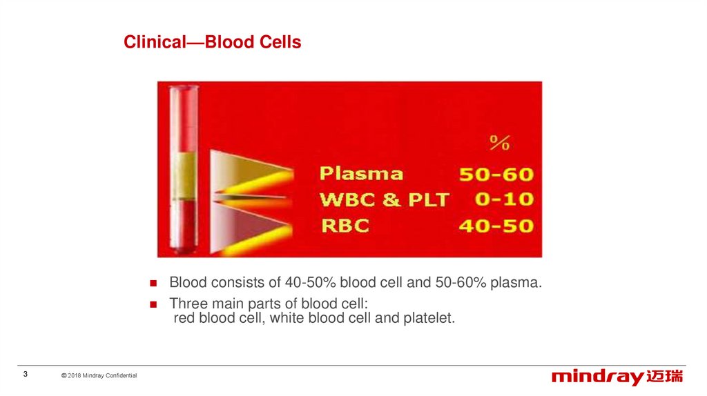
Blood consists of 40-50% blood cell and 50-60% plasma.
Three main parts of blood cell:
red blood cell, white blood cell and platelet.
4.
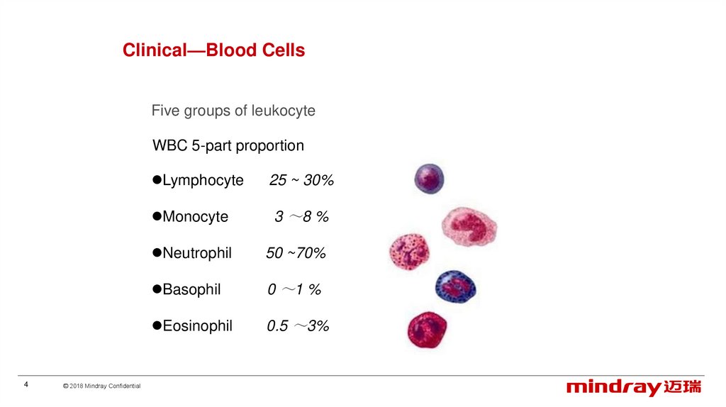
Clinical—Blood CellsFive groups of leukocyte
WBC 5-part proportion
4
© 2018 Mindray Confidential
Lymphocyte
25 ~ 30%
Monocyte
3 8 %
Neutrophil
50 ~70%
Basophil
0 1 %
Eosinophil
0.5 3%
5.
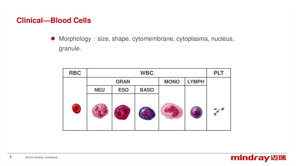
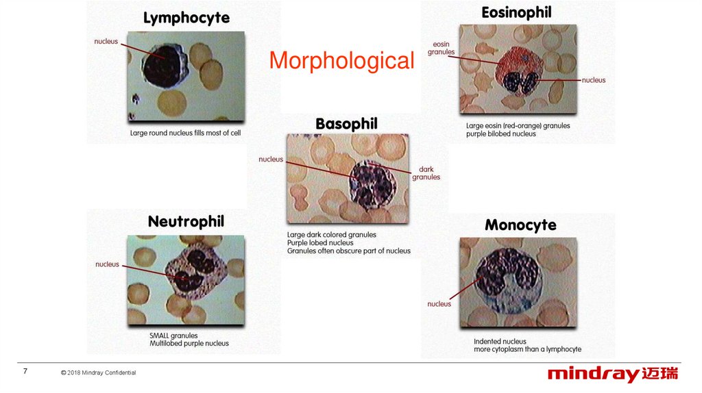
Clinical—Blood CellsMorphology size, shape, cytomembrane, cytoplasma, nucleus,
granule.
RBC
WBC
GRAN
NEU
5
© 2018 Mindray Confidential
ESO
PLT
MONO
BASO
LYMPH
6.
Clinical—Blood Cells6
© 2018 Mindray Confidential
7.
Morphological7
© 2018 Mindray Confidential
8.
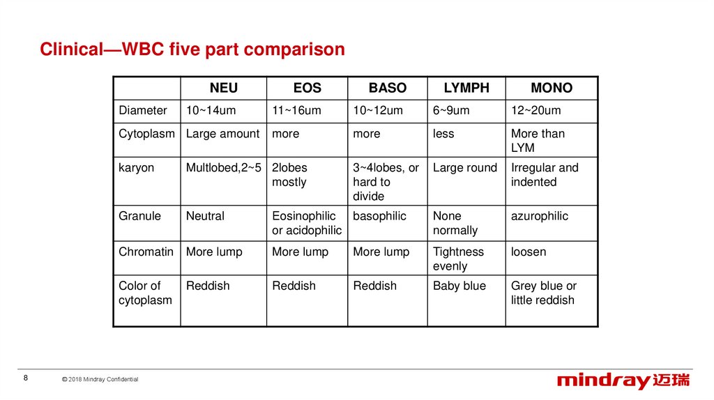
Clinical—WBC five part comparisonDiameter
NEU
EOS
BASO
10~14um
11~16um
10~12um
6~9um
12~20um
more
more
less
More than
LYM
3~4lobes, or
hard to
divide
Large round
Irregular and
indented
Cytoplasm Large amount
8
LYMPH
MONO
karyon
Multlobed,2~5 2lobes
mostly
Granule
Neutral
Eosinophilic basophilic
or acidophilic
None
normally
azurophilic
Chromatin
More lump
More lump
More lump
Tightness
evenly
loosen
Color of
cytoplasm
Reddish
Reddish
Reddish
Baby blue
Grey blue or
little reddish
© 2018 Mindray Confidential
9.
Clinical —granules in cytoplasmNeutral
Eosinophilic
basophilic
Azurophilic
Size
Fine and even
Thick and even
Most thick and
uneven
Thicker than
NEU, uneven
Shape
Fine particles
Round or ellipse
Differ in shape
Differ in shape
Amount
Much
Much
Less
A few or
moderate
Color
Pale violet red
or reddish
Orange red or
dark yellow
Royal purple or
dark purple
Purple red
Even
Even
Uneven, coat
the nucleus
normally
Uneven, coat
the nucleus
occasionally
Distribution
9
© 2018 Mindray Confidential
10.
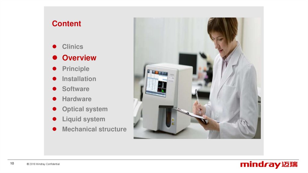
ContentClinics
Overview
Principle
Installation
Software
Hardware
Optical system
Liquid system
Mechanical structure
10
© 2018 Mindray Confidential
11.
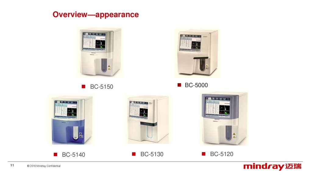
Overview—appearanceBC-5000
BC-5150
BC-5140
11
© 2018 Mindray Confidential
BC-5130
BC-5120
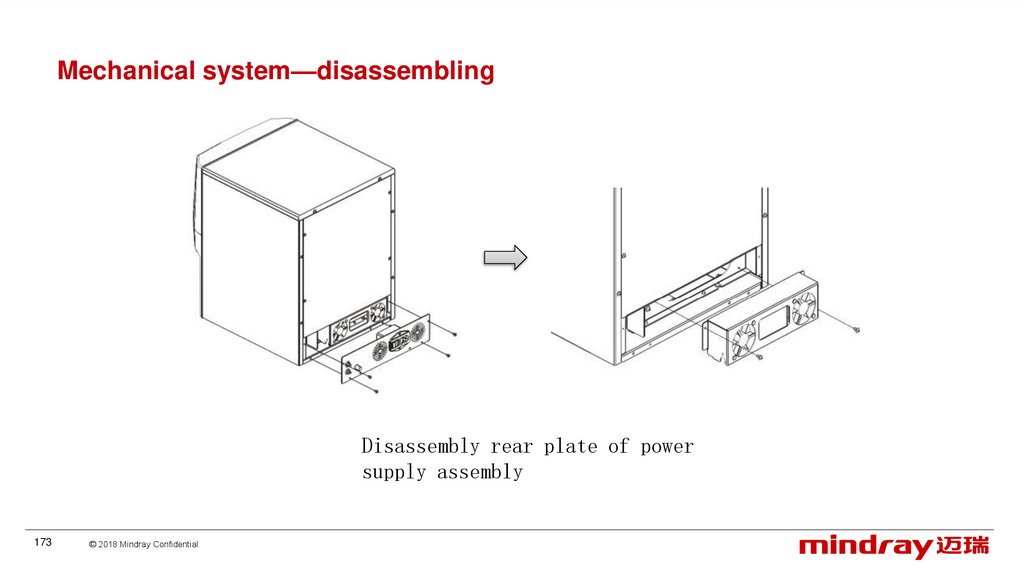
12.
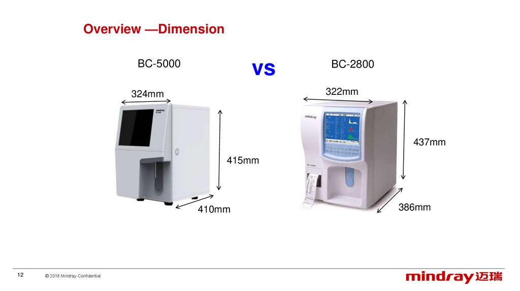
Overview —DimensionBC-5000
vs
BC-2800
322mm
324mm
437mm
415mm
410mm
12
© 2018 Mindray Confidential
386mm
13.
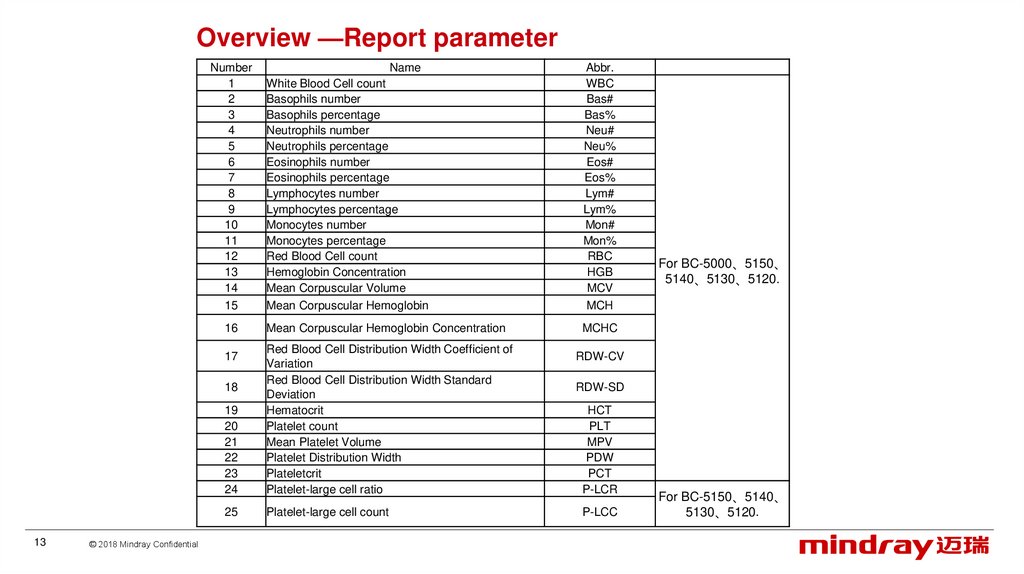
Overview —Report parameterNumber
1
2
3
4
5
6
7
8
9
10
11
12
13
14
15
16
Mean Corpuscular Hemoglobin Concentration
MCHC
19
20
21
22
23
24
25
Platelet-large cell count
18
© 2018 Mindray Confidential
Abbr.
WBC
Bas#
Bas%
Neu#
Neu%
Eos#
Eos%
Lym#
Lym%
Mon#
Mon%
RBC
HGB
MCV
MCH
Red Blood Cell Distribution Width Coefficient of
Variation
Red Blood Cell Distribution Width Standard
Deviation
Hematocrit
Platelet count
Mean Platelet Volume
Platelet Distribution Width
Plateletcrit
Platelet-large cell ratio
17
13
Name
White Blood Cell count
Basophils number
Basophils percentage
Neutrophils number
Neutrophils percentage
Eosinophils number
Eosinophils percentage
Lymphocytes number
Lymphocytes percentage
Monocytes number
Monocytes percentage
Red Blood Cell count
Hemoglobin Concentration
Mean Corpuscular Volume
Mean Corpuscular Hemoglobin
For BC-5000、5150、
5140、5130、5120.
RDW-CV
RDW-SD
HCT
PLT
MPV
PDW
PCT
P-LCR
P-LCC
For BC-5150、5140、
5130、5120.
14.
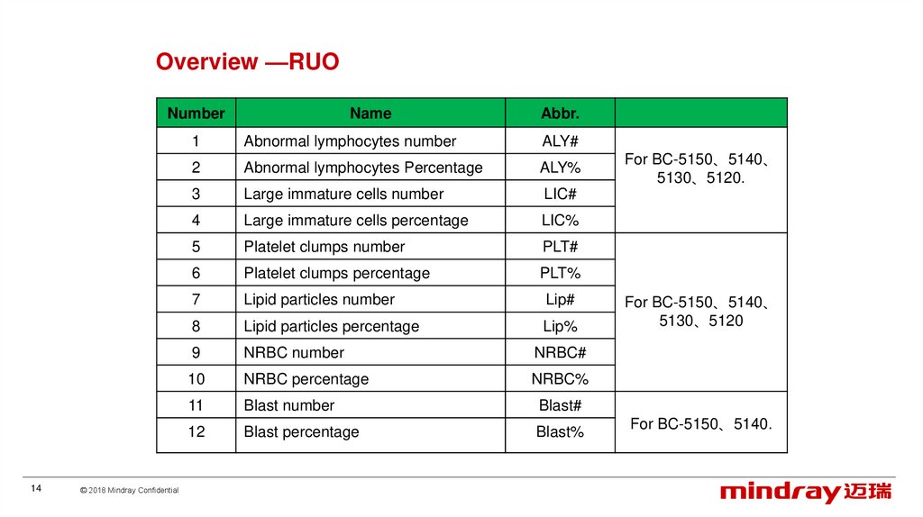
Overview —RUONumber
14
© 2018 Mindray Confidential
Name
Abbr.
1
Abnormal lymphocytes number
ALY#
2
Abnormal lymphocytes Percentage
ALY%
3
Large immature cells number
LIC#
4
Large immature cells percentage
LIC%
5
Platelet clumps number
PLT#
6
Platelet clumps percentage
PLT%
7
Lipid particles number
Lip#
8
Lipid particles percentage
Lip%
9
NRBC number
NRBC#
10
NRBC percentage
NRBC%
11
Blast number
Blast#
12
Blast percentage
Blast%
For BC-5150、5140、
5130、5120.
For BC-5150、5140、
5130、5120
For BC-5150、5140.
15.
Overview —appearance1、Display screen
2、Power/status indicator
3、Probe wipe block
4、Sample probe
5、[ Aspirate] key
Front of the analyzer
15
© 2018 Mindray Confidential
16.
Overview —appearance1、Diluent inlet
2、Waste outlet
3、Waste sensor
4、AC input socket
5、Power switch
6、Air outlet for fan
7、Back panel
Back of the analyzer
16
© 2018 Mindray Confidential
17.
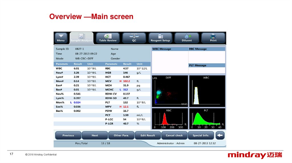
Overview —Main screen17
© 2018 Mindray Confidential
18.
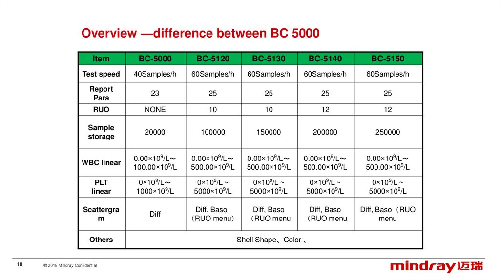
Overview —difference between BC 5000Item
BC-5000
BC-5120
BC-5130
BC-5140
BC-5150
Test speed
40Samples/h
60Samples/h
60Samples/h
60Samples/h
60Samples/h
Report
Para
23
25
25
25
25
RUO
NONE
10
10
12
12
Sample
storage
20000
100000
150000
200000
250000
WBC linear
0.00×10⁹/L
100.00×10⁹/L
0.00×10⁹/L
500.00×10⁹/L
0.00×10⁹/L
500.00×10⁹/L
0.00×10⁹/L
500.00×10⁹/L
0.00×10⁹/L
500.00×10⁹/L
PLT
linear
0×109/L
1000×109/L
0×109/L ~
5000×109/L
0×109/L ~
5000×109/L
0×109/L ~
5000×109/L
0×109/L ~
5000×109/L
Scattergra
m
Diff
Diff, Baso
RUO menu
Diff, Baso
RUO menu
Diff, Baso
RUO menu
Diff, Baso RUO
menu
Others
18
© 2018 Mindray Confidential
Shell Shape、Color 、
19.
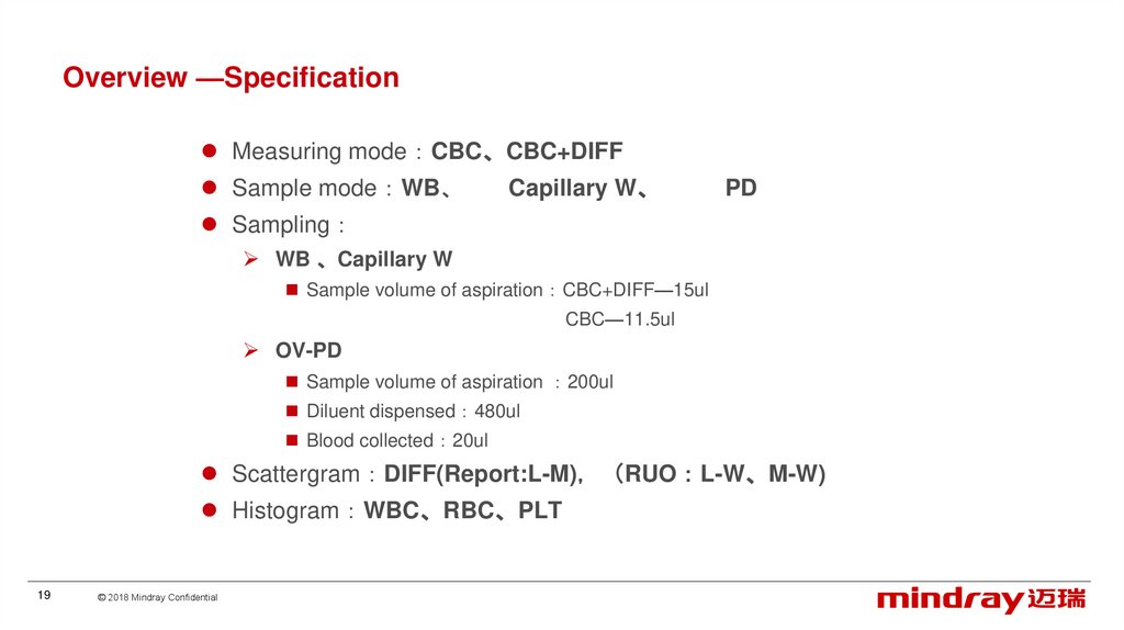
Overview —SpecificationMeasuring mode CBC、CBC+DIFF
Sample mode WB、
Capillary W、
PD
Sampling
WB 、Capillary W
Sample volume of aspiration CBC+DIFF—15ul
CBC—11.5ul
OV-PD
Sample volume of aspiration 200ul
Diluent dispensed 480ul
Blood collected 20ul
Scattergram DIFF(Report:L-M) RUO L-W、M-W)
Histogram WBC、RBC、PLT
19
© 2018 Mindray Confidential
20.
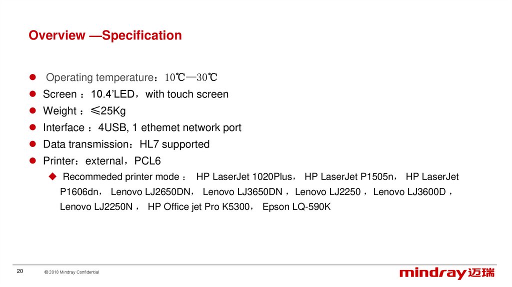
Overview —SpecificationOperating temperature 10℃—30℃
Screen 10.4’LED with touch screen
Weight ≤25Kg
Interface 4USB, 1 ethemet network port
Data transmission HL7 supported
Printer external PCL6
Recommeded printer mode HP LaserJet 1020Plus HP LaserJet P1505n HP LaserJet
P1606dn Lenovo LJ2650DN Lenovo LJ3650DN Lenovo LJ2250 Lenovo LJ3600D
Lenovo LJ2250N HP Office jet Pro K5300 Epson LQ-590K
20
© 2018 Mindray Confidential
21.
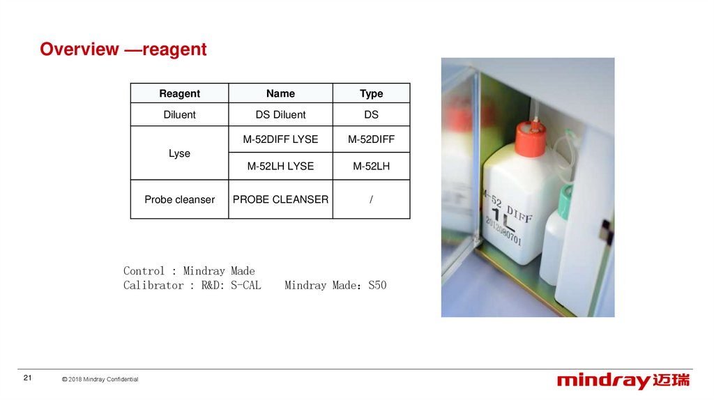
Overview —reagentReagent
Name
Type
Diluent
DS Diluent
DS
M-52DIFF LYSE
M-52DIFF
M-52LH LYSE
M-52LH
PROBE CLEANSER
/
Lyse
Probe cleanser
Control : Mindray Made
Calibrator : R&D: S-CAL
21
© 2018 Mindray Confidential
Mindray Made S50
22.
ContentClinics
Overview
Principle
Installation
Software
Hardware
Optical system
Liquid system
Mechanical structure
22
© 2018 Mindray Confidential
23.
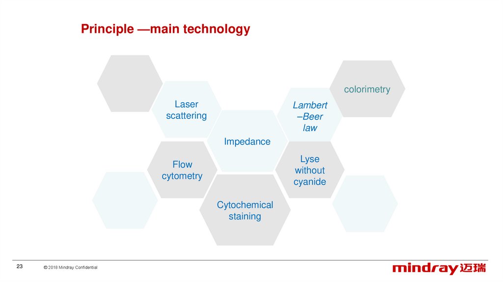
Principle —main technologycolorimetry
Laser
scattering
Lambert
–Beer
law
Impedance
Lyse
without
cyanide
Flow
cytometry
Cytochemical
staining
23
© 2018 Mindray Confidential
24.
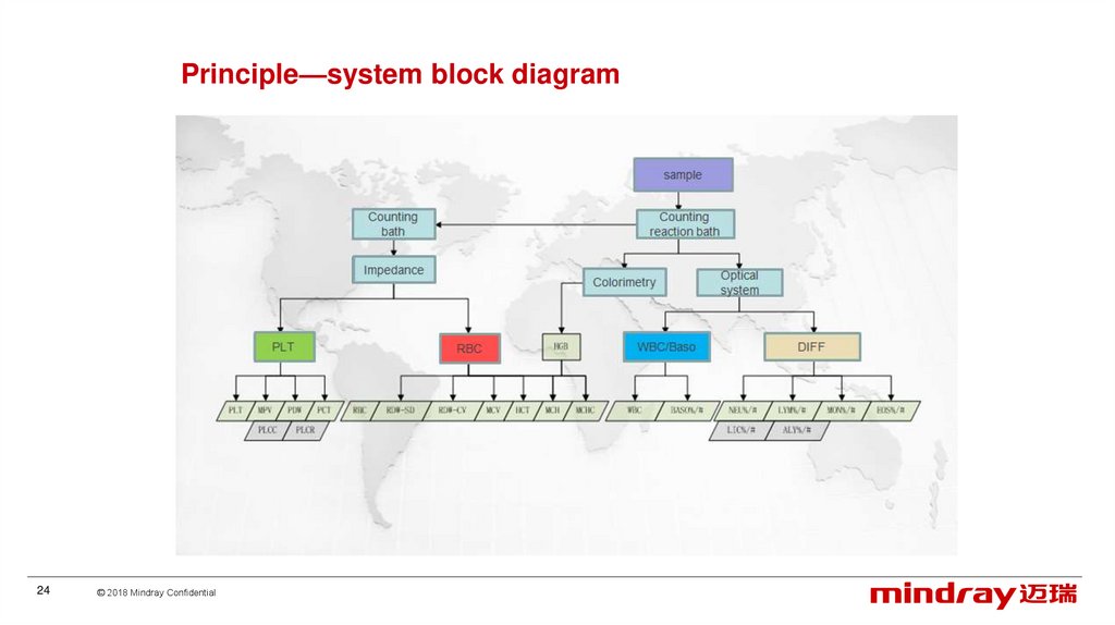
Principle—system block diagram24
© 2018 Mindray Confidential
25.
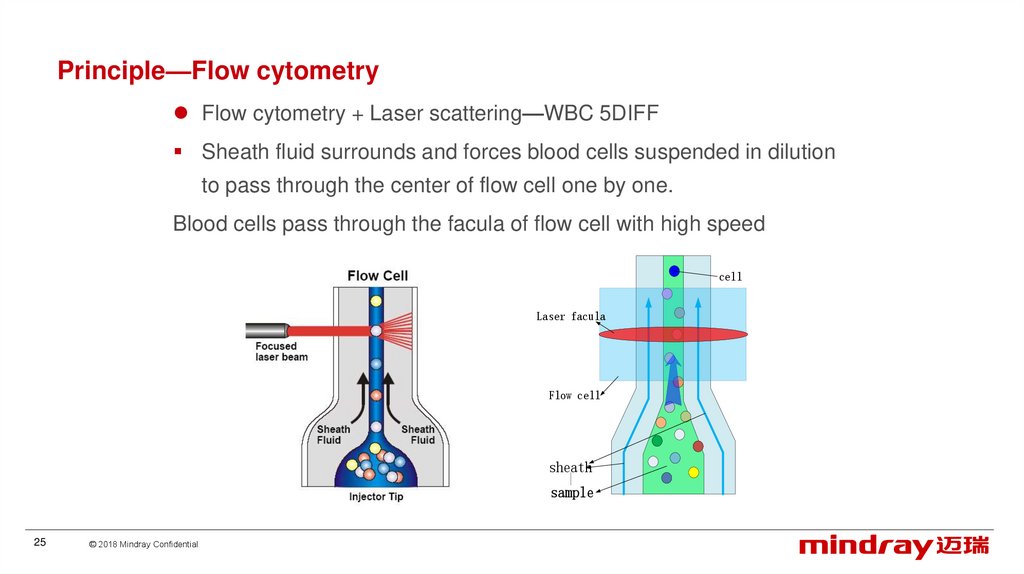
Principle—Flow cytometryFlow cytometry + Laser scattering—WBC 5DIFF
Sheath fluid surrounds and forces blood cells suspended in dilution
to pass through the center of flow cell one by one.
Blood cells pass through the facula of flow cell with high speed
cell
Laser facula
Flow cell
sheath
sample
25
© 2018 Mindray Confidential
26.
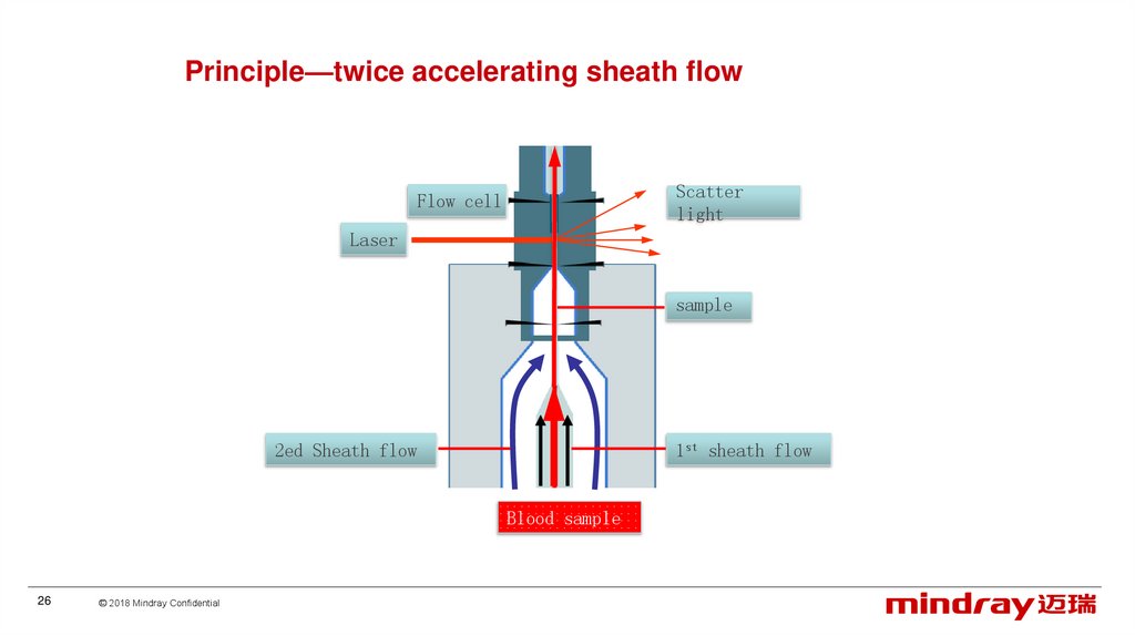
Principle—twice accelerating sheath flowScatter
light
Flow cell
Laser
sample
1st sheath flow
2ed Sheath flow
Blood sample
26
© 2018 Mindray Confidential
27.
Principle—Multi-angle laser scatteringMulti-angle laser scattering
27
LAS—volume of the cells
MAS—inner complexity
WAS—granularity of the cells
© 2018 Mindray Confidential
28.
Principle—cytochemical stainingM-52 DIFF Lyse
Cationic surfactant To dissolve the RBC special treatment to WBC
anionic group stain the granular of the WBC
Lymph
Mono
Nue
Eos
original
After adding
reagent
More difference in complexity
28
© 2018 Mindray Confidential
Baso
29.
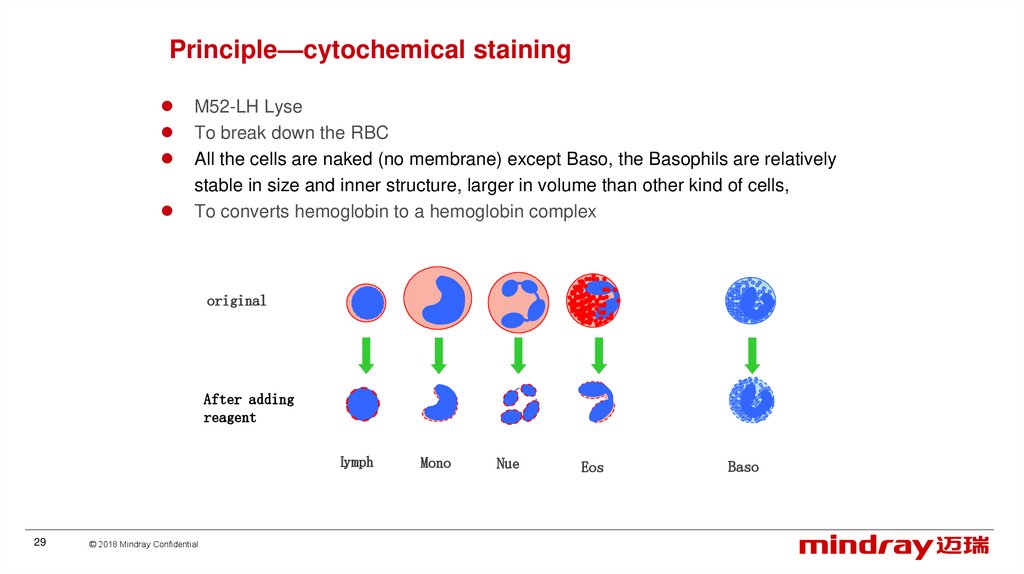
Principle—cytochemical stainingM52-LH Lyse
To break down the RBC
All the cells are naked (no membrane) except Baso, the Basophils are relatively
stable in size and inner structure, larger in volume than other kind of cells,
To converts hemoglobin to a hemoglobin complex
original
After adding
reagent
Lymph
29
© 2018 Mindray Confidential
Mono
Nue
Eos
Baso
30.
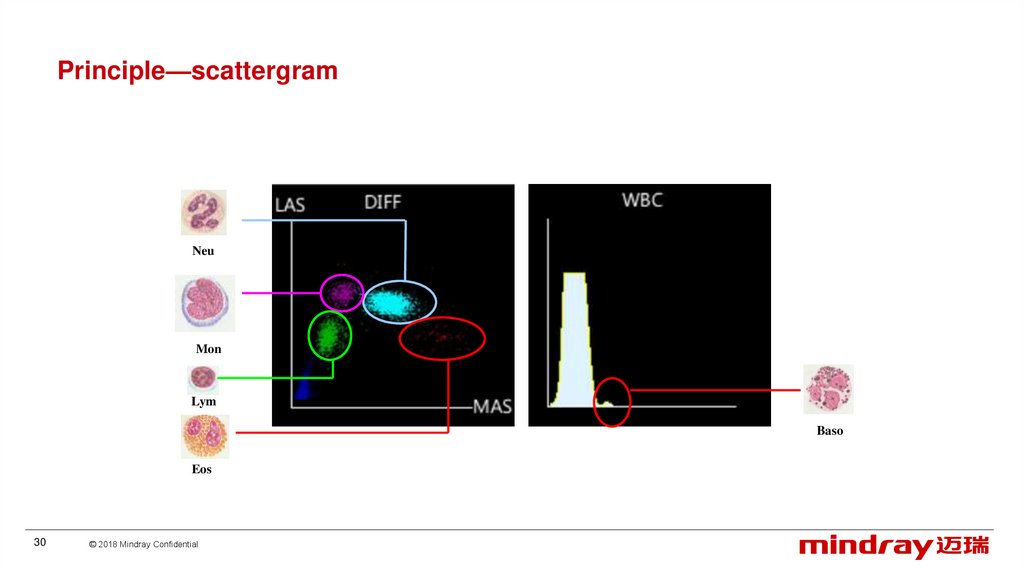
Principle—scattergramNeu
Mon
Lym
Baso
Eos
30
© 2018 Mindray Confidential
31.
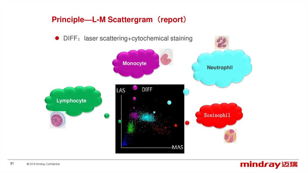
Principle—L-M Scattergram reportDIFF laser scattering+cytochemical staining
Monocyte
Neutrophil
Lymphocyte
Eosinophil
31
© 2018 Mindray Confidential
32.
Principle—scattergram (RUO)L-W scattergram M-W scattergram special for Eos more
accurate to large amount of EOS.
Eosinophil
32
© 2018 Mindray Confidential
33.
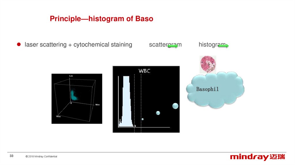
Principle—histogram of Basolaser scattering + cytochemical staining
scattergram
histogram
Basophil
33
© 2018 Mindray Confidential
34.
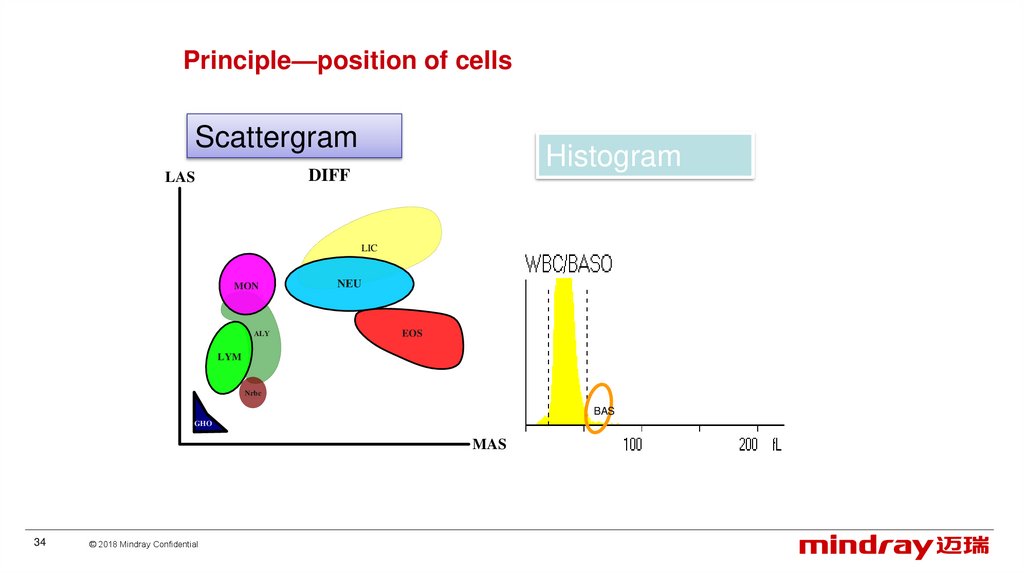
Principle—position of cellsScattergram
Histogram
DIFF
LAS
LIC
LIC
MON
ALY
NEU
EOS
LYM
Nrbc
BAS
GHO
MAS
34
© 2018 Mindray Confidential
35.
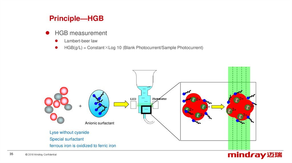
Principle—HGBHGB measurement
Lambert-beer law
HGB(g/L) = Constant×Log 10 (Blank Photocurrent/Sample Photocurrent)
Fe 2+
Fe 2+
Fe
Fe 2+
Fe
Fe 2+
Anionic surfactant
Lyse without cyanide
Special surfactant
ferrous iron is oxidized to ferric iron
35
© 2018 Mindray Confidential
3+
Fe
3+
Fe
3+
3+
36.
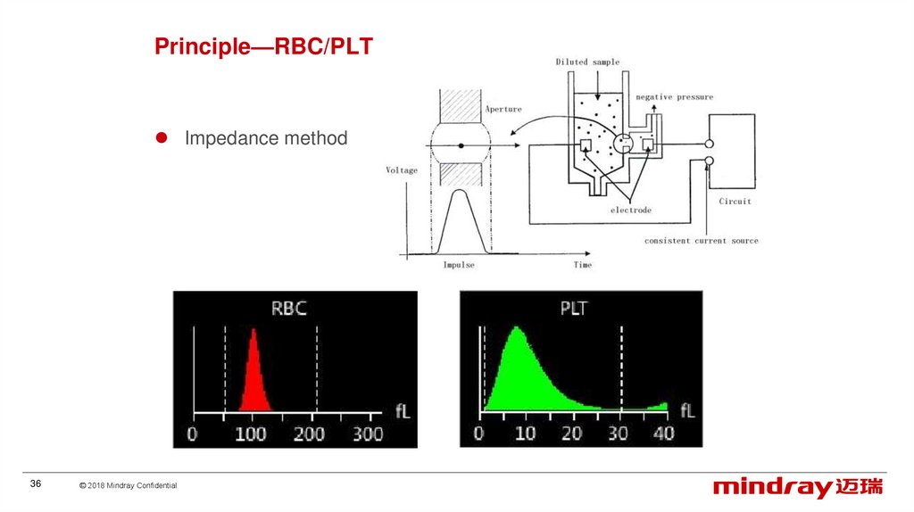
Principle—RBC/PLTImpedance method
36
© 2018 Mindray Confidential
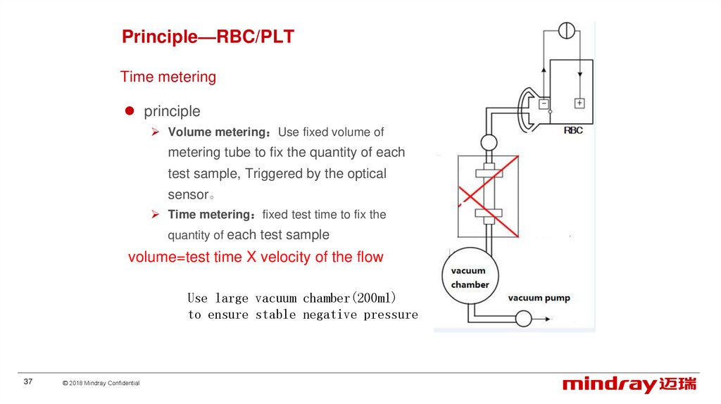
37.
Principle—RBC/PLTTime metering
principle
Volume metering Use fixed volume of
metering tube to fix the quantity of each
test sample, Triggered by the optical
sensor。
Time metering fixed test time to fix the
quantity of each test sample
volume=test time X velocity of the flow
Use large vacuum chamber(200ml)
to ensure stable negative pressure
37
© 2018 Mindray Confidential
38.
Principle—RBC/PLTTest time
• Accurate hardware timing RBC 9s
How to ensure stable flow velocity
• Stable negative pressure
• Abnormal monitoring
1.Stable aperture voltage
2.Stable particle stream
Aperture voltage: 14.75V23.75V
38
© 2018 Mindray Confidential
39.
ContentClinics
Overview
Principle
Installation
Software
Hardware
Optical system
Liquid system
Mechanical structure
39
© 2018 Mindray Confidential
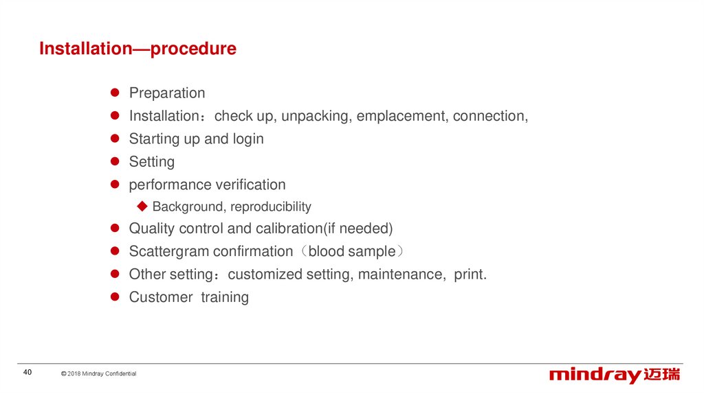
40.
Installation—procedurePreparation
Installation check up, unpacking, emplacement, connection,
Starting up and login
Setting
performance verification
Background, reproducibility
Quality control and calibration(if needed)
Scattergram confirmation blood sample
Other setting customized setting, maintenance, print.
Customer training
40
© 2018 Mindray Confidential
41.
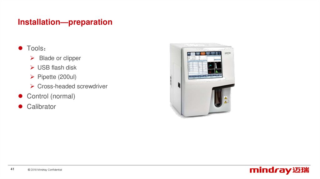
Installation—preparationTools
Blade or clipper
USB flash disk
Pipette (200ul)
Cross-headed screwdriver
Control (normal)
Calibrator
41
© 2018 Mindray Confidential
42.
Installation—preparationEnvironment
should be as free as possible from dust, mechanical vibrations, and electrical interference;
Far from brush-type motors, flickering fluorescent lights, and electrical contacts that regularly open
and close;
Do not place the analyzer on a slope;
Do not place the analyzer in direct sunlight or in front of a source of heat or drafts;
The environment shall be well ventilated
42
© 2018 Mindray Confidential
43.
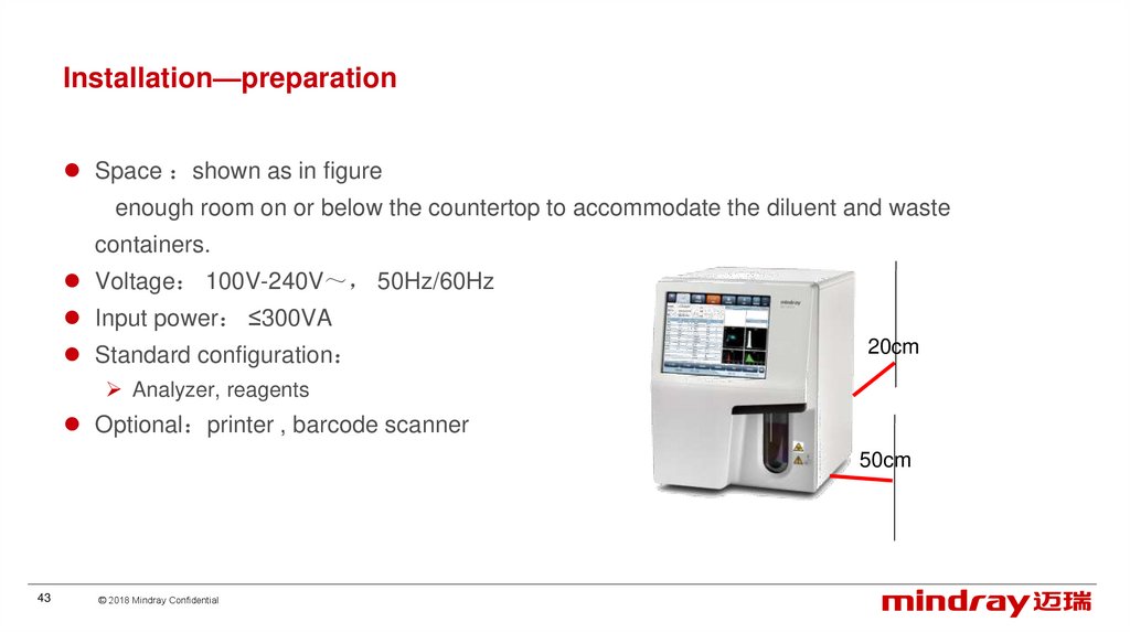
Installation—preparationSpace shown as in figure
enough room on or below the countertop to accommodate the diluent and waste
containers.
Voltage 100V-240V 50Hz/60Hz
Input power ≤300VA
Standard configuration
20cm
Analyzer, reagents
Optional printer , barcode scanner
50cm
43
© 2018 Mindray Confidential
44.
Installation-unpackingCheck
outer packing and apparatus
Packing list and contents
Apparatus arrangement
44
© 2018 Mindray Confidential
45.
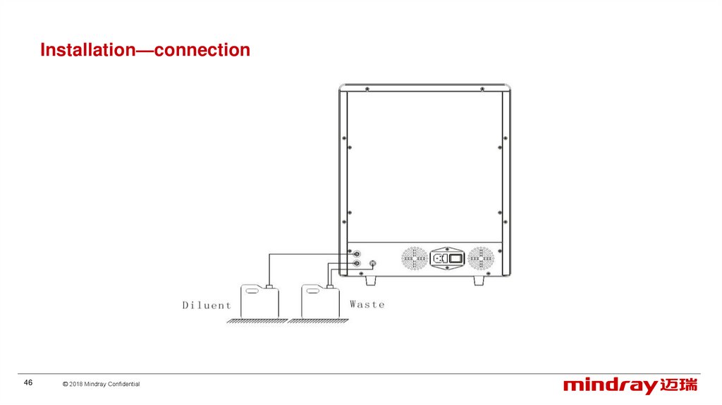
Installation—connectionPower switch
DS diluent
inlet
Waste outlet
45
© 2018 Mindray Confidential
Waste sensor connector
Power socket
46.
Installation—connection46
© 2018 Mindray Confidential
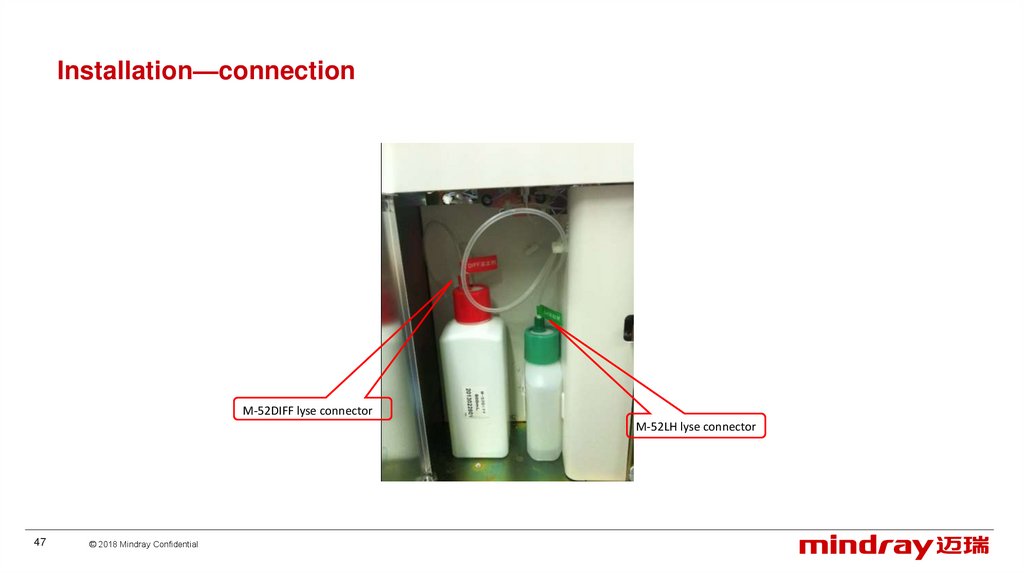
47.
Installation—connectionM-52DIFF lyse connector
M-52LH lyse connector
47
© 2018 Mindray Confidential
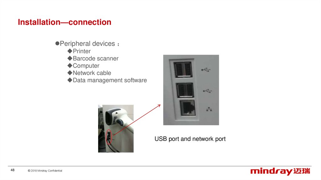
48.
Installation—connectionPeripheral devices
Printer
Barcode scanner
Computer
Network cable
Data management software
USB port and network port
48
© 2018 Mindray Confidential
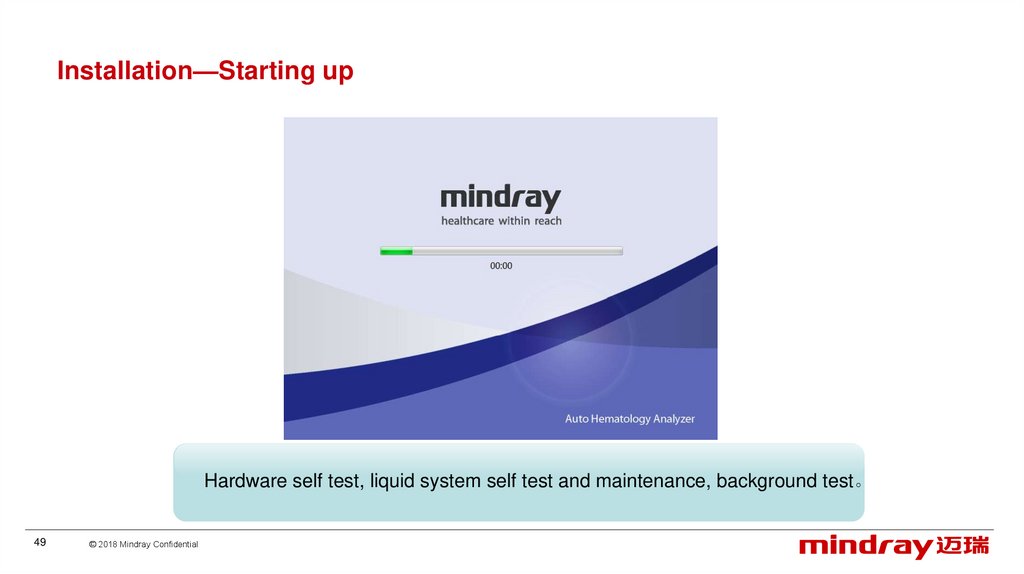
49.
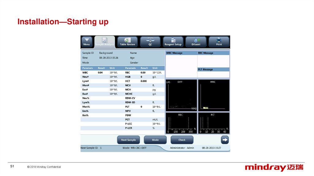
Installation—Starting upHardware self test, liquid system self test and maintenance, background test。
49
© 2018 Mindray Confidential
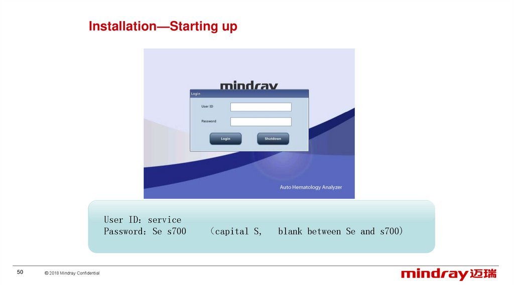
50.
Installation—Starting upUser ID service
Password Se s700
50
© 2018 Mindray Confidential
capital S,
blank between Se and s700)
51.
Installation—Starting up51
© 2018 Mindray Confidential
52.
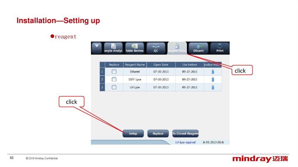
Installation—Setting upreagent
click
click
52
© 2018 Mindray Confidential
53.
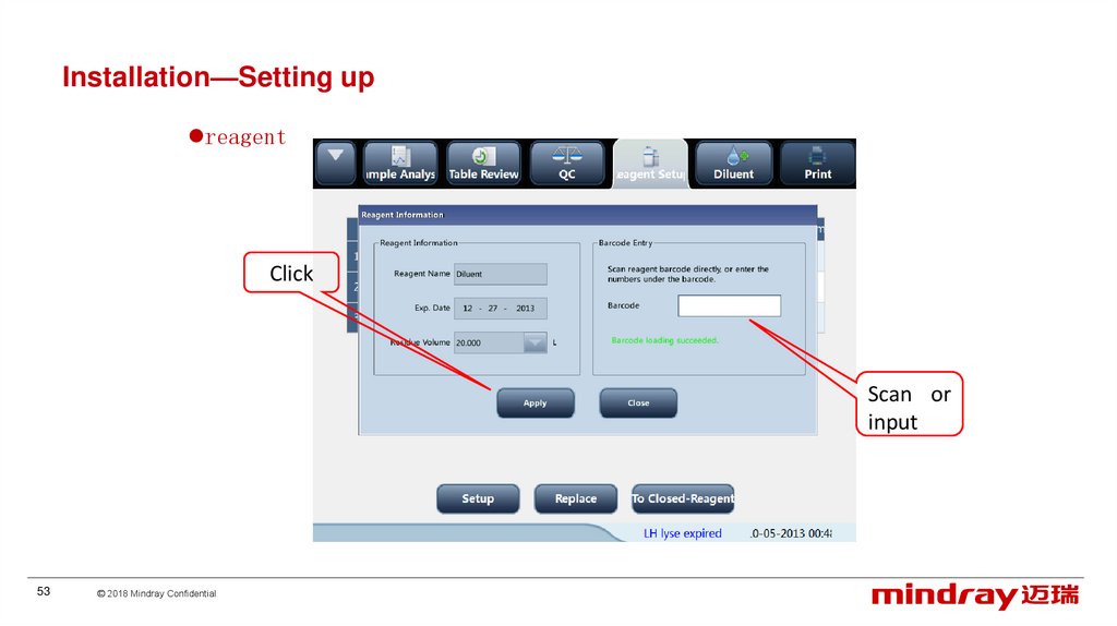
Installation—Setting upreagent
Click
Scan or
input
53
© 2018 Mindray Confidential
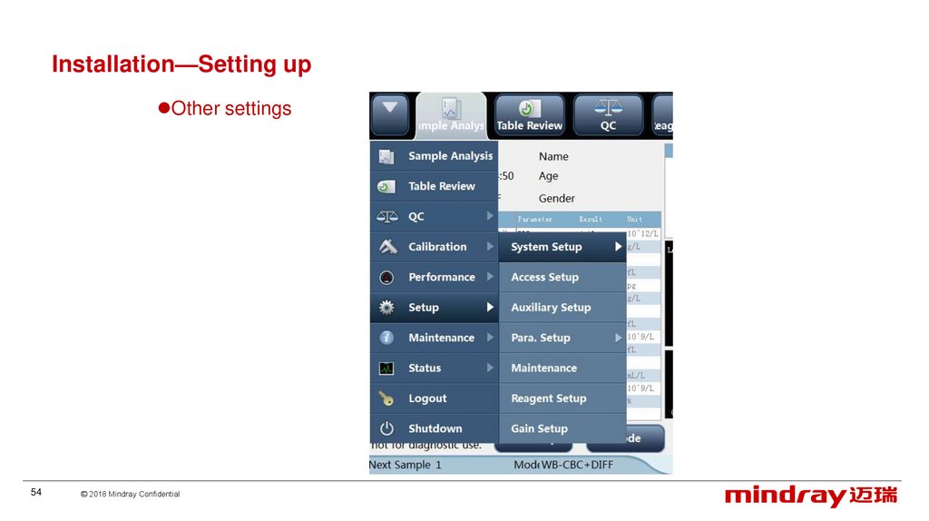
54.
Installation—Setting upOther settings
54
© 2018 Mindray Confidential
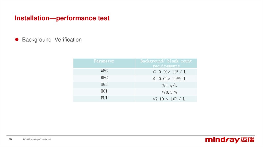
55.
Installation—performance testBackground Verification
Parameter
55
© 2018 Mindray Confidential
WBC
Background/ blank count
requirements
≤ 0.20 109 / L
RBC
≤ 0.02 1012/ L
HGB
≤1 g/L
HCT
≤0.5 %
PLT
≤ 10 109 / L
56.
Installation—performance testBackground Verification
56
© 2018 Mindray Confidential
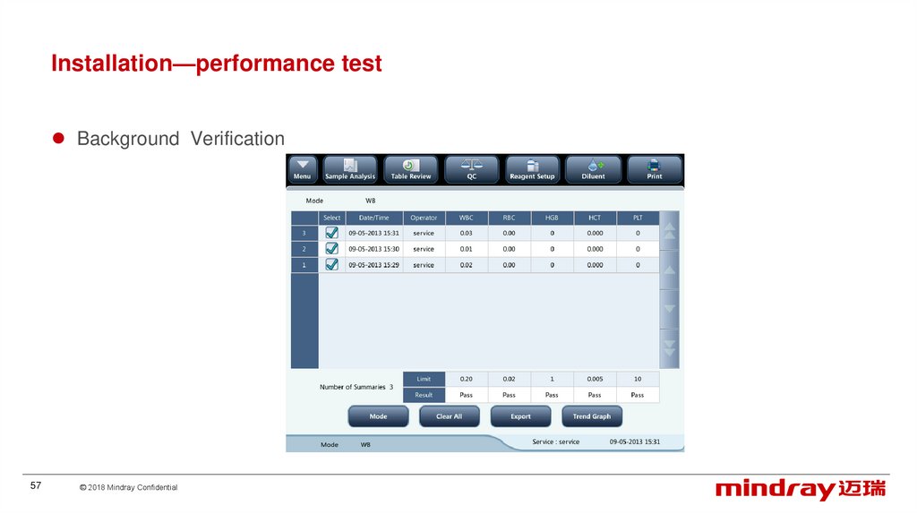
57.
Installation—performance testBackground Verification
57
© 2018 Mindray Confidential
58.
Installation—performance testReproducibility
58
© 2018 Mindray Confidential
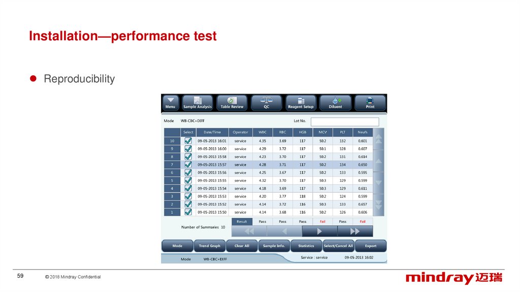
59.
Installation—performance testReproducibility
59
© 2018 Mindray Confidential
60.
Installation—quality controlclick
60
© 2018 Mindray Confidential
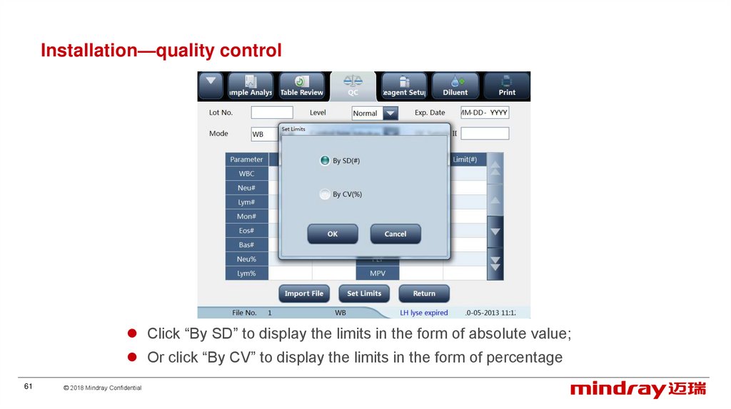
61.
Installation—quality controlClick “By SD” to display the limits in the form of absolute value;
Or click “By CV” to display the limits in the form of percentage
61
© 2018 Mindray Confidential
62.
ContentClinics
Overview
Principle
Installation
Software
Hardware
Optical system
Liquid system
Mechanical structure
62
© 2018 Mindray Confidential
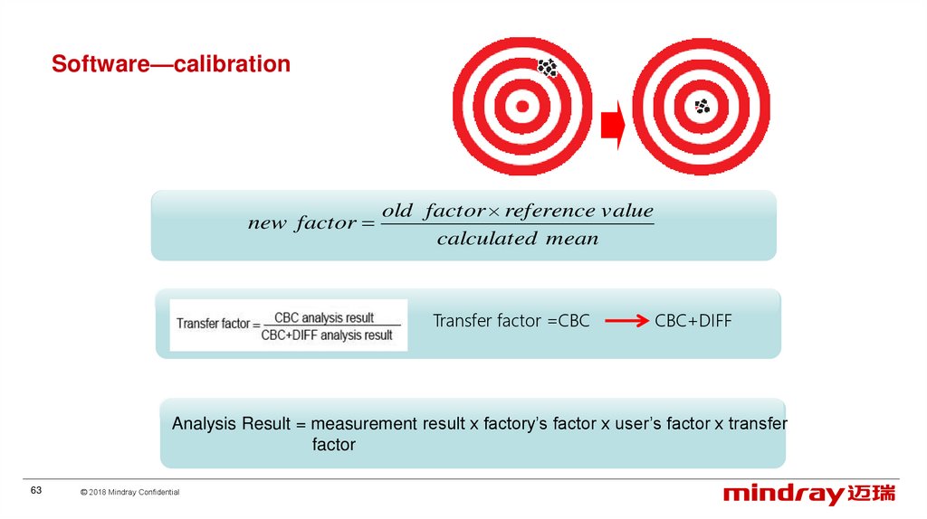
63.
Software—calibrationnew factor
old factor reference value
calculated mean
Transfer factor =CBC
CBC+DIFF
Analysis Result = measurement result x factory’s factor x user’s factor x transfer
factor
63
© 2018 Mindray Confidential
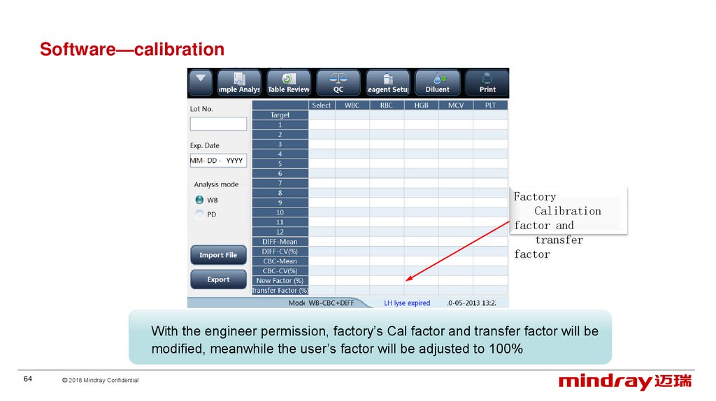
64.
Software—calibrationFactory
Calibration
factor and
transfer
factor
With the engineer permission, factory’s Cal factor and transfer factor will be
modified, meanwhile the user’s factor will be adjusted to 100%
64
© 2018 Mindray Confidential
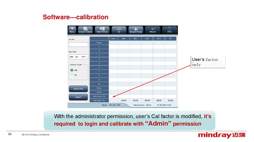
65.
Software—calibrationUser’s factor
only
With the administrator permission, user’s Cal factor is modified, it’s
required to login and calibrate with “Admin” permission
65
© 2018 Mindray Confidential
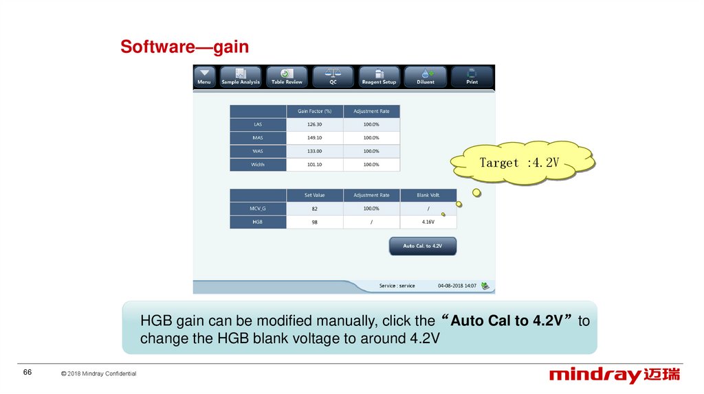
66.
Software—gainTarget :4.2V
HGB gain can be modified manually, click the“Auto Cal to 4.2V”to
change the HGB blank voltage to around 4.2V
66
© 2018 Mindray Confidential
67.
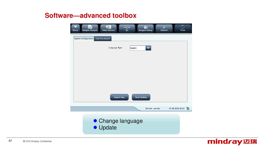
Software—advanced toolboxChange language
Update
67
© 2018 Mindray Confidential
68.
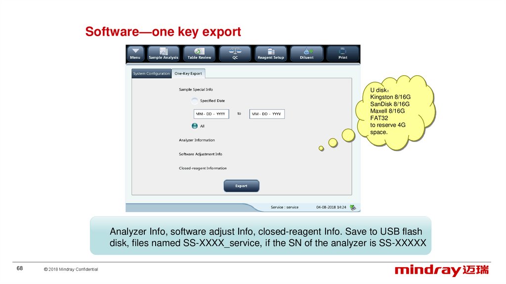
Software—one key exportU disk
Kingston 8/16G
SanDisk 8/16G
Maxell 8/16G
FAT32
to reserve 4G
space.
Analyzer Info, software adjust Info, closed-reagent Info. Save to USB flash
disk, files named SS-XXXX_service, if the SN of the analyzer is SS-XXXXX
68
© 2018 Mindray Confidential
69.
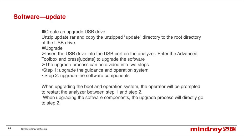
Software—updateCreate an upgrade USB drive
Unzip update.rar and copy the unzipped “update” directory to the root directory
of the USB drive.
Upgrade
Insert the USB drive into the USB port on the analyzer. Enter the Advanced
Toolbox and press[update] to upgrade the software
The upgrade process can be divided into two steps.
•Step 1: upgrade the guidance and operation system
• Step 2: upgrade the software components
When upgrading the boot and operation system, the operator will be prompted
to restart the analyzer between step 1 and step 2.
When upgrading the software components, the upgrade process will directly go
to step 2.
69
© 2018 Mindray Confidential
70.
Software—communicationIP addresses of the PC and the analyzer shall be in the same
IP segment
Default IP of the analyzer 10.0.0.2
70
© 2018 Mindray Confidential
71.
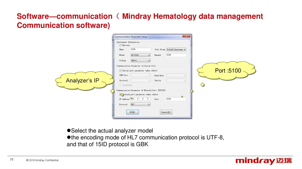
Software—communication Mindray Hematology data managementCommunication software)
Port :5100
Analyzer’s IP
Select the actual analyzer model
the encoding mode of HL7 communication protocol is UTF-8,
and that of 15ID protocol is GBK
71
© 2018 Mindray Confidential
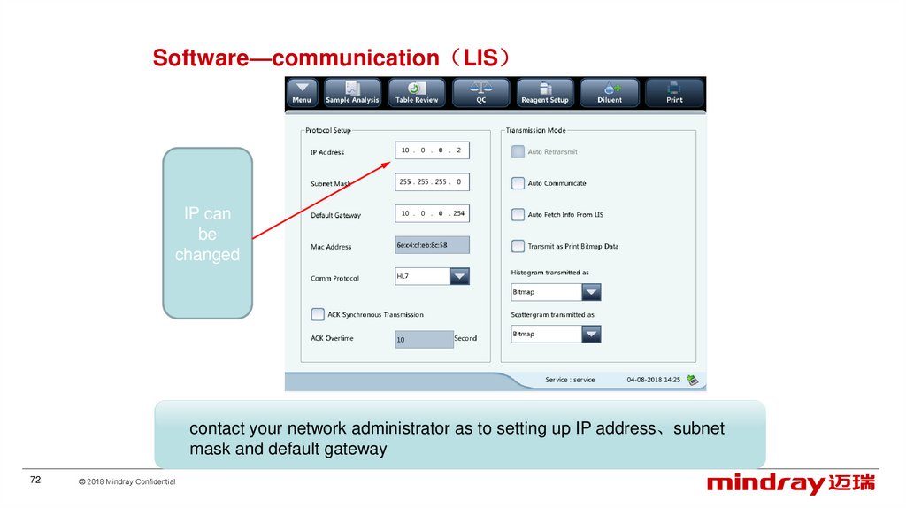
72.
Software—communication LISIP can
be
changed
contact your network administrator as to setting up IP address、subnet
mask and default gateway
72
© 2018 Mindray Confidential
73.
ContentClinics
Overview
Principle
Installation
Software
Hardware
Optical system
Liquid system
Mechanical structure
73
© 2018 Mindray Confidential
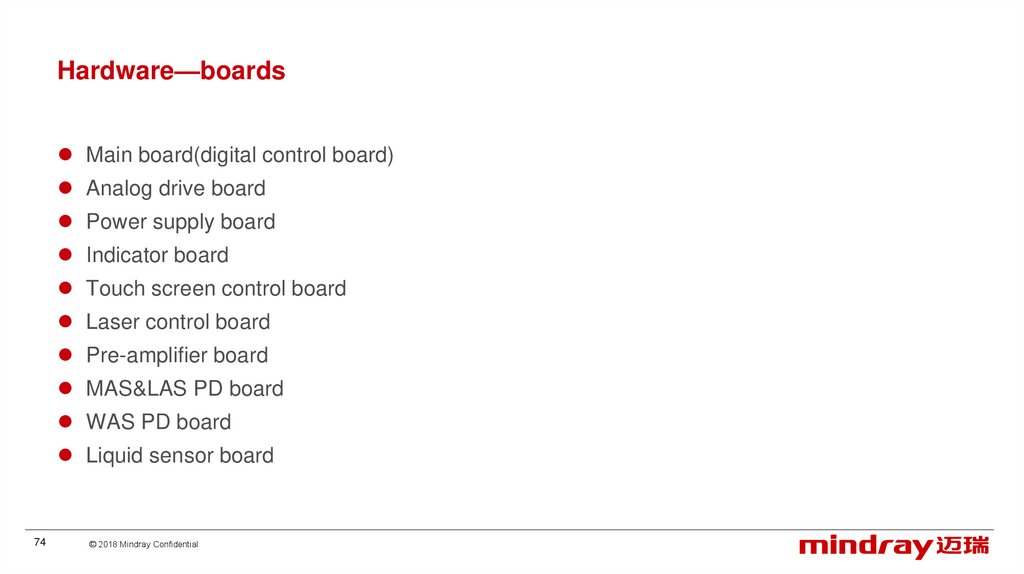
74.
Hardware—boardsMain board(digital control board)
Analog drive board
Power supply board
Indicator board
Touch screen control board
Laser control board
Pre-amplifier board
MAS&LAS PD board
WAS PD board
Liquid sensor board
74
© 2018 Mindray Confidential
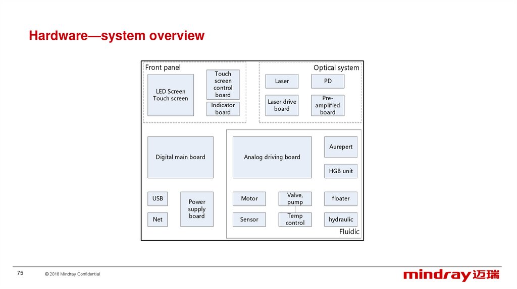
75.
Hardware—system overviewFront panel
LED Screen
Touch screen
Optical system
Touch
screen
control
board
Indicator
board
Laser
PD
Laser drive
board
Preamplified
board
Aurepert
Digital main board
Analog driving board
HGB unit
USB
Net
Power
supply
board
Motor
Valve,
pump
floater
Sensor
Temp
control
hydraulic
Fluidic
75
© 2018 Mindray Confidential
76.
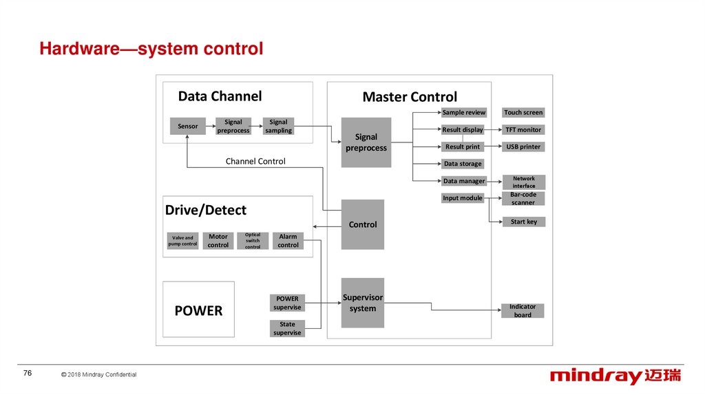
Hardware—system controlData Channel
Sensor
Signal
preprocess
Master Control
Signal
sampling
Signal
preprocess
Channel Control
Control
Motor
control
POWER
Optical
switch
control
© 2018 Mindray Confidential
Result display
TFT monitor
Result print
USB printer
Data manager
Network
interface
Input module
Bar-code
scanner
Start key
Alarm
control
POWER
supervise
State
supervise
76
Touch screen
Data storage
Drive/Detect
Valve and
pump control
Sample review
Supervisor
system
Indicator
board
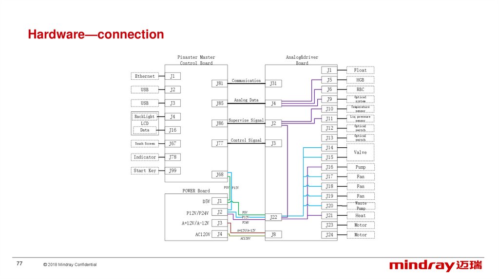
77.
Hardware—connectionPinaster Master
Control Board
Ethernet
Analog&driver
Board
J1
J81
USB
USB
BackLight
J3
J85
J4
J86
Touch Screen
J67
Indicator
J78
Start Key
J99
J77
Supervise Signal
J4
J2
Control Signal
J3
Float
J5
HGB
J6
RBC
J9
Optical
system
J10
Temperature
sensor
J11
Liq pressure
sensor
J12
Optical
switch
J13
Optical
switch
J14
Valve
J15
J68
P5V P12V
D5V
J1
P12V/P24V
J2
P5V
P12V
A+12V/A-12V
J3
P24V
AC120V
© 2018 Mindray Confidential
Analog Data
J16
POWER Board
77
J31
J2
LCD
Data
Communication
J1
J4
A+12V/A-12V
AC120V
J22
J8
J16
Pump
J17
Fan
J18
Fan
J19
Fan
J20
Waste
Pump
J21
Heat
J23
Motor
J24
Motor
78.
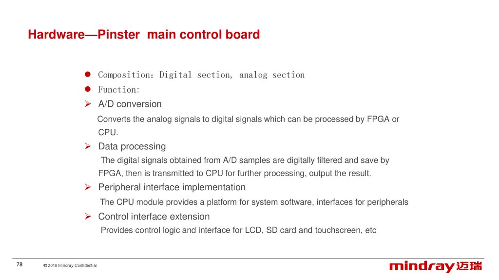
Hardware—Pinster main control boardComposition Digital section, analog section
Function:
A/D conversion
Converts the analog signals to digital signals which can be processed by FPGA or
CPU.
Data processing
The digital signals obtained from A/D samples are digitally filtered and save by
FPGA, then is transmitted to CPU for further processing, output the result.
Peripheral interface implementation
The CPU module provides a platform for system software, interfaces for peripherals
Control interface extension
Provides control logic and interface for LCD, SD card and touchscreen, etc
78
© 2018 Mindray Confidential
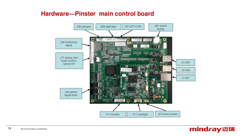
79.
Hardware—Pinster main control board79
© 2018 Mindray Confidential
80.
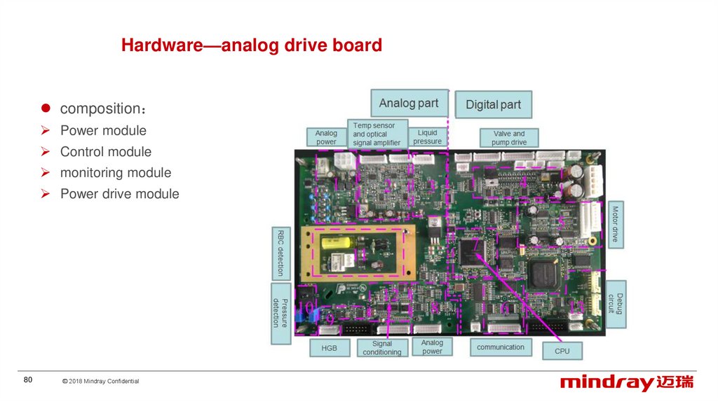
Hardware—analog drive boardcomposition
Power module
Control module
monitoring module
Power drive module
80
© 2018 Mindray Confidential
81.
Hardware—analog drive boardPower module
supplies power for all the electronic devices on the analog drive board, including both input power from the analog
drive board, and the power converted by the chip;
Main control module
responsible for communicating with the control board and task scheduling;
Monitoring module
collecting information such as temperature, pressure, voltage and fluid in the tubes;
Power driving module
driving electric components such as motor, heater, fan, valves and pumps;
RBC detection circuit
provides the RBC module with constant current source, RBC signal collection and modulation;
Modulation of optical signals and HGB signals.
81
© 2018 Mindray Confidential
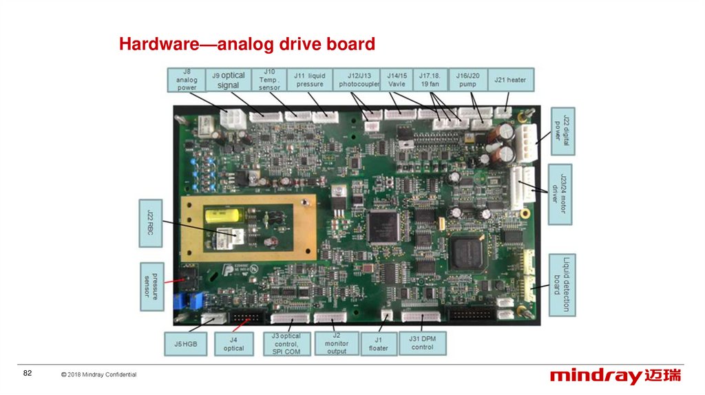
82.
Hardware—analog drive board82
© 2018 Mindray Confidential
83.
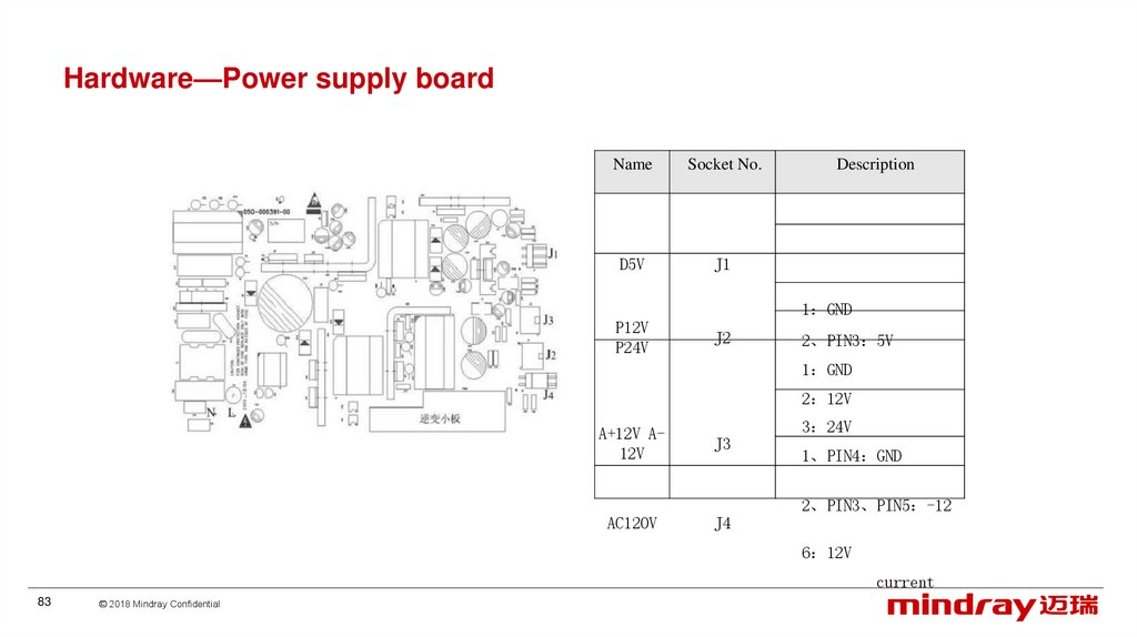
Hardware—Power supply boardName
Socket No.
D5V
J1
Description
PIN1 GND
P12V
P24V
J2
PIN2、PIN3 5V
PIN1 GND
PIN2 12V
PIN3 24V
A+12V A12V
J3
AC120V
J4
PIN1、PIN4 GND
PIN2、PIN3、PIN5 -12V
PIN6 12V
Alternating current
83
© 2018 Mindray Confidential
84.
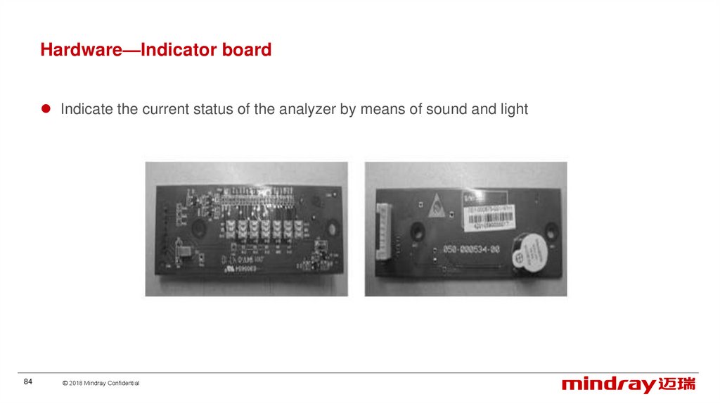
Hardware—Indicator boardIndicate the current status of the analyzer by means of sound and light
84
© 2018 Mindray Confidential
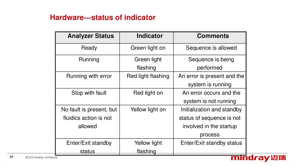
85.
Hardware—status of indicatorAnalyzer Status
Indicator
Comments
Ready
Green light on
Sequence is allowed
Running
Green light
Sequence is being
Running with error
flashing
Red light flashing
Stop with fault
Red light on
performed
An error is present and the
system is running
An error occurs and the
No fault is present, but
fluidics action is not
allowed
Enter/Exit standby
status
85
© 2018 Mindray Confidential
Yellow light on
Yellow light
flashing
system is not running
Initialization and standby
status of sequence is not
involved in the startup
process
Enter/Exit standby status
86.
Hardware—buzzerEvent
Buzzer Prompts
Startup completed
One short beep
Open-vial aspiration completed
When count operation can not be
started in count related screens
(including Sample Analysis, QC,
Calibration, Reproducibility,
Carryover, Background, Aging and
Optical Gain Calibration Count, etc.),
press the aspirate key
Error
Analyzer is ready
When the screen is black
prompting “Please power off the
analyzer”
86
© 2018 Mindray Confidential
Two short beeps
One long beep
Long intermittent
beeps
One short beep
stop beep
Comments
Startup completed means the
whole startup process has been
completed and the analyzer is
ready for operation
If these screens have already
prompted, then the buzzer need
not be responded again.
Tap the touchscreen to stop the
buzzer
Analyzer enters ready status
from other status
If an error occurs during the
shutdown process, the buzzer will
stop beeping when the screen is
black
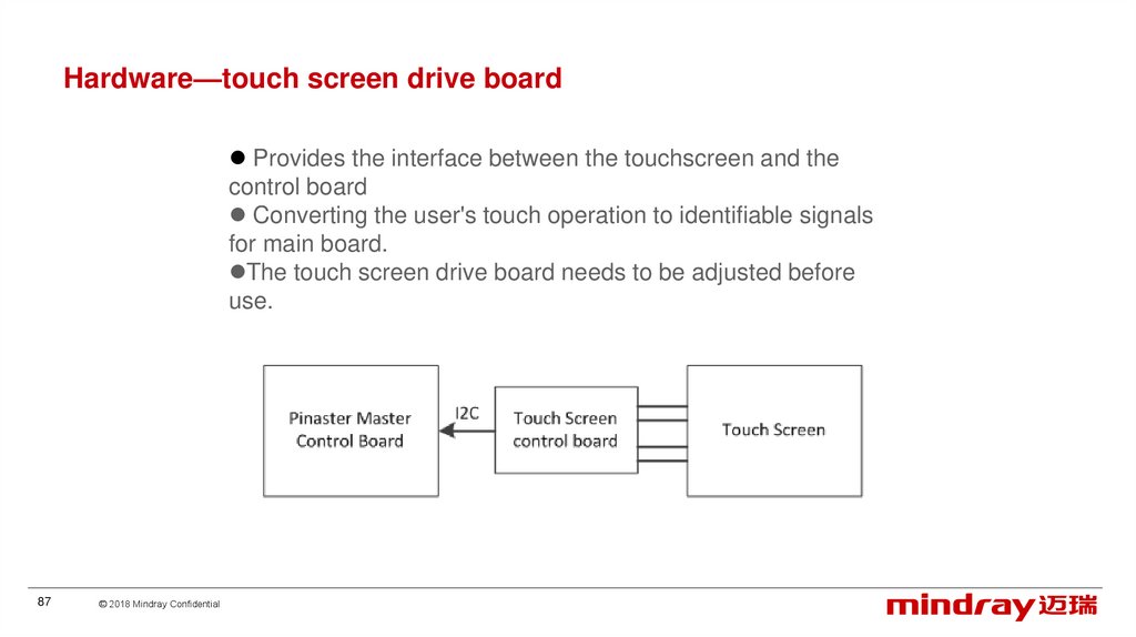
87.
Hardware—touch screen drive boardProvides the interface between the touchscreen and the
control board
Converting the user's touch operation to identifiable signals
for main board.
The touch screen drive board needs to be adjusted before
use.
87
© 2018 Mindray Confidential
88.
Hardware—Liquid sensor boardLED and Test point TP4
output lower than 0.8V, the LED light is off, (have reagent)
output higher than 2V, the LED light is on, (no reagent)
88
© 2018 Mindray Confidential
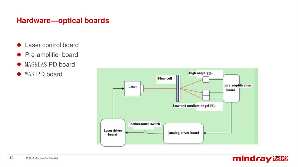
89.
Hardware—optical boardsLaser control board
Pre-amplifier board
MAS&LAS PD board
WAS PD board
89
© 2018 Mindray Confidential
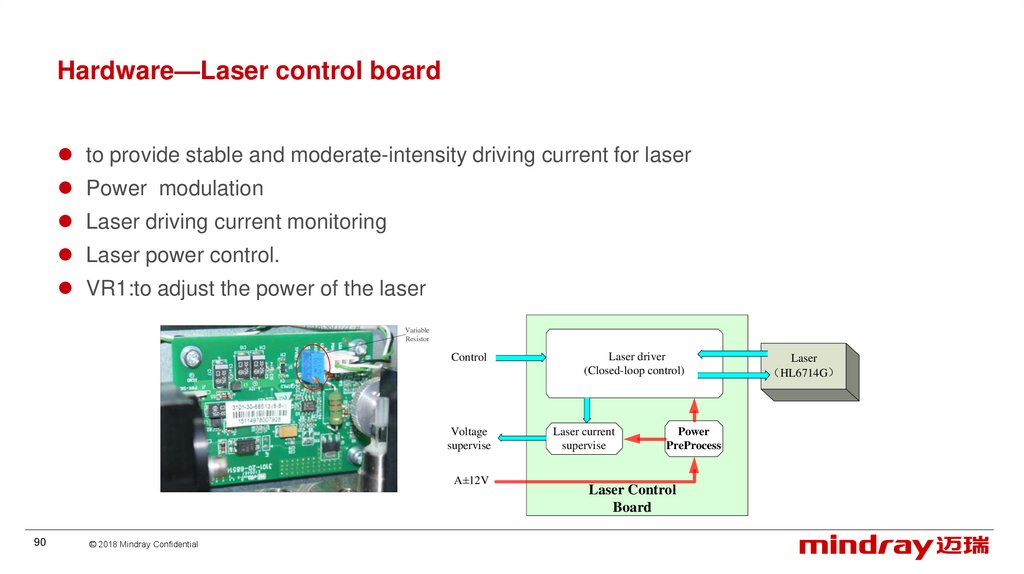
90.
Hardware—Laser control boardto provide stable and moderate-intensity driving current for laser
Power modulation
Laser driving current monitoring
Laser power control.
VR1:to adjust the power of the laser
Variable
Resistor
Control
Voltage
supervise
A±12V
90
© 2018 Mindray Confidential
Laser driver
(Closed-loop control)
Laser current
supervise
Power
PreProcess
Laser Control
Board
Laser
HL6714G
91.
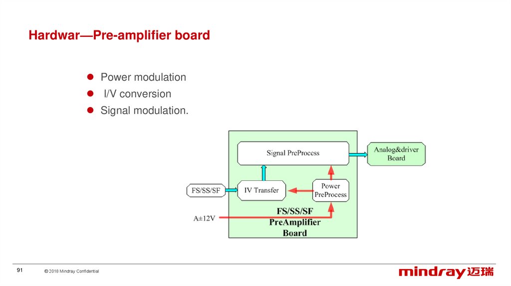
Hardwar—Pre-amplifier boardPower modulation
I/V conversion
Signal modulation.
91
© 2018 Mindray Confidential
92.
ContentClinics
Overview
Principle
Installation
Software
Hardware
Optical system
Liquid system
Mechanical structure
92
© 2018 Mindray Confidential
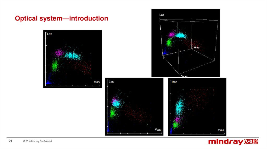
93.
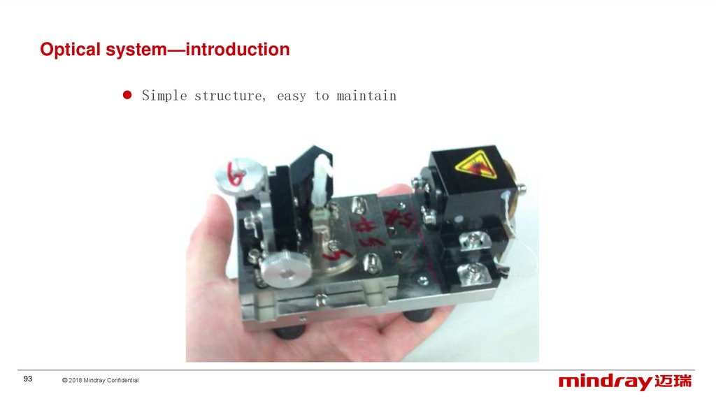
Optical system—introductionSimple structure, easy to maintain
93
© 2018 Mindray Confidential
94.
Optical system—introductionOmit backward optical assembly, to receive scatter signal
directly with a large size PD instead, make it small and low
cost
3106 optical
3107optical
94
© 2018 Mindray Confidential
95.
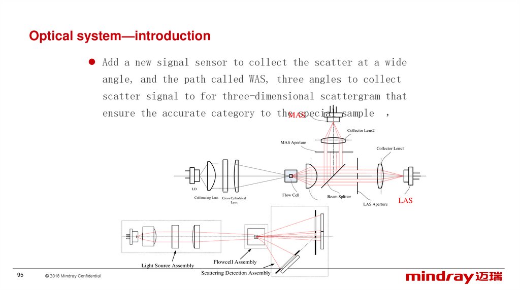
Optical system—introductionAdd a new signal sensor to collect the scatter at a wide
angle, and the path called WAS, three angles to collect
scatter signal to for three-dimensional scattergram that
ensure the accurate category to theMAS
special sample
Collector Lens2
MAS Aperture
Collector Lens1
LD
Collimating Lens
Light Source Assembly
95
© 2018 Mindray Confidential
Cross Cylindrical
Lens
Flowcell Assembly
Scattering Detection Assembly
Flow Cell
Beam Splitter
LAS Aperture
LAS
96.
Optical system—introduction96
© 2018 Mindray Confidential
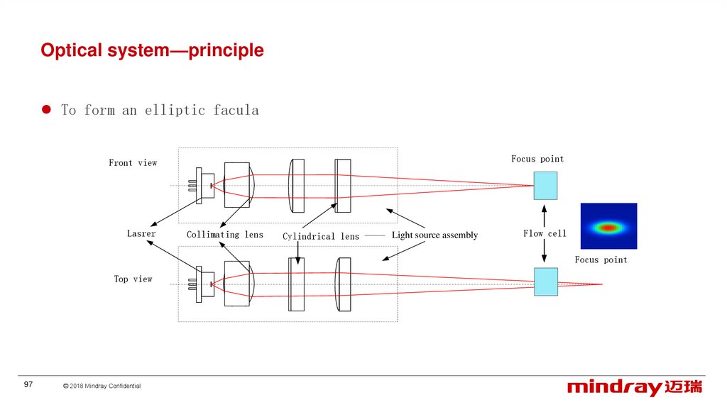
97.
Optical system—principleTo form an elliptic facula
Focus point
Front view
Lasrer
Collimating lens
Cylindrical lens
Light source assembly
Flow cell
Focus point
Top view
97
© 2018 Mindray Confidential
98.
Optical system—principleFacula and signal light intensity in horizontal direction
V
t
98
© 2018 Mindray Confidential
样本流
99.
Optical system—principleOval facula -Gaussian distribution
Vertical direction: cover an entire blood cell
Horizontal direction wider than that of sample flow, even light intensity in detection area.
cell
Laser facula
Flow cell
sheath
sample
99
© 2018 Mindray Confidential
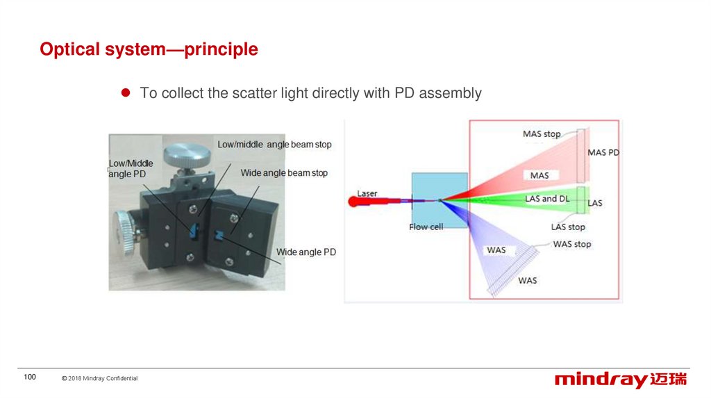
100.
Optical system—principleTo collect the scatter light directly with PD assembly
100
© 2018 Mindray Confidential
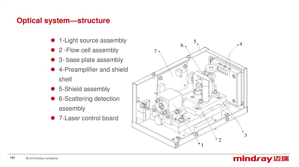
101.
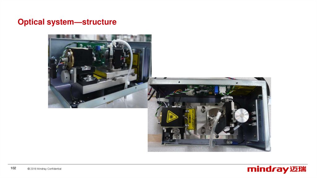
Optical system—structure1-Light source assembly
2 -Flow cell assembly
6
5
4
7
3- base plate assembly
4-Preamplifier and shield
shell
5-Shield assembly
6-Scattering detection
assembly
7-Laser control board
3
2
1
101
© 2018 Mindray Confidential
102.
Optical system—structure102
© 2018 Mindray Confidential
103.
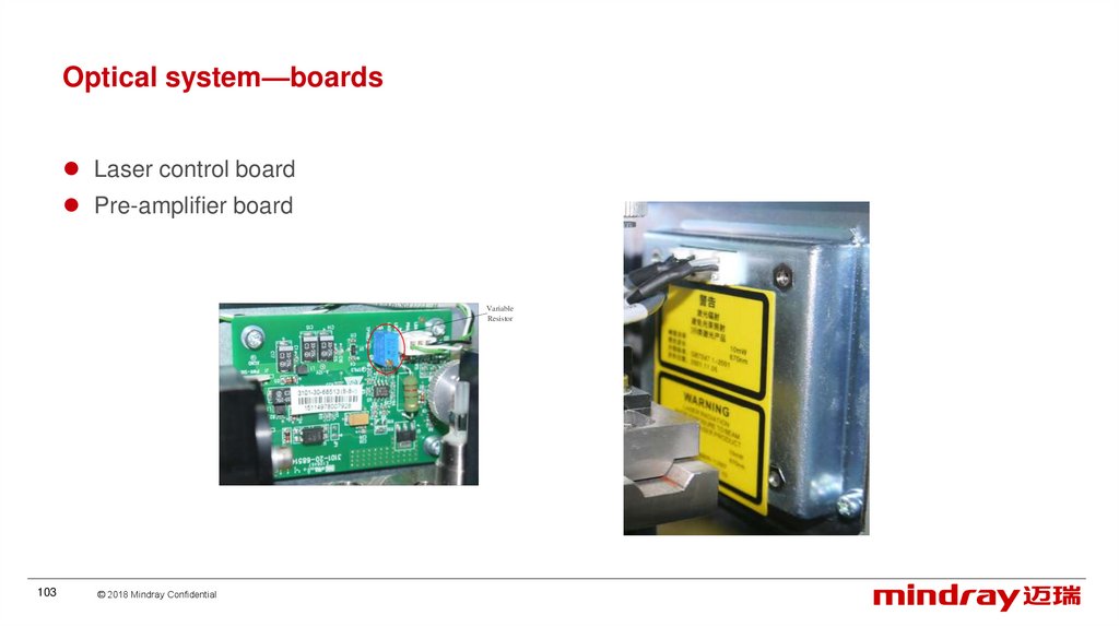
Optical system—boardsLaser control board
Pre-amplifier board
Variable
Resistor
103
© 2018 Mindray Confidential
104.
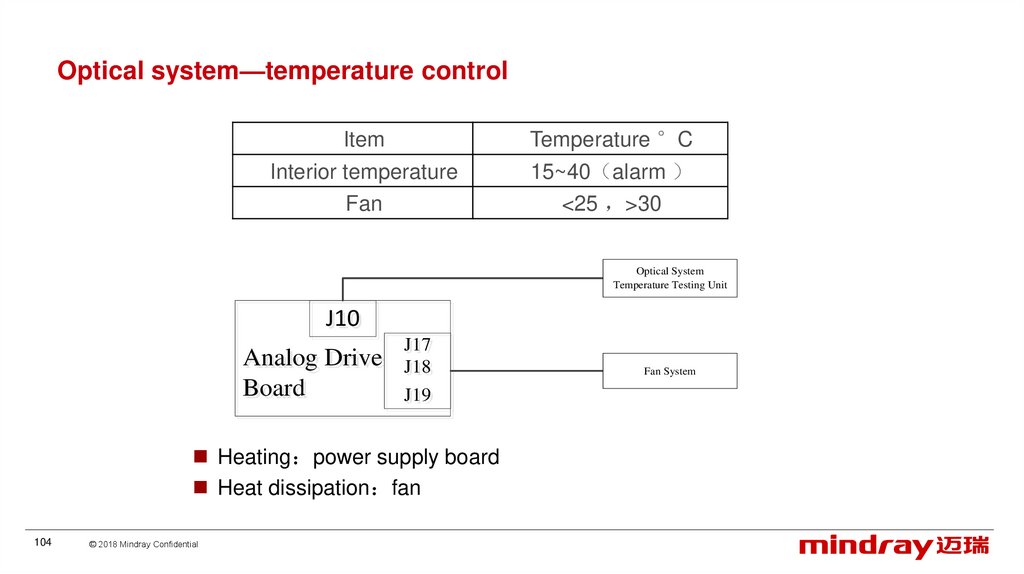
Optical system—temperature controlItem
Interior temperature
Fan
Temperature °C
15~40 alarm
<25 >30
Optical System
Temperature Testing Unit
J10
J10
Analog
Analog Drive
Drive
Board
Board
J17
J17
J18
J18
J19
J19
Heating power supply board
Heat dissipation fan
104
© 2018 Mindray Confidential
Fan System
105.
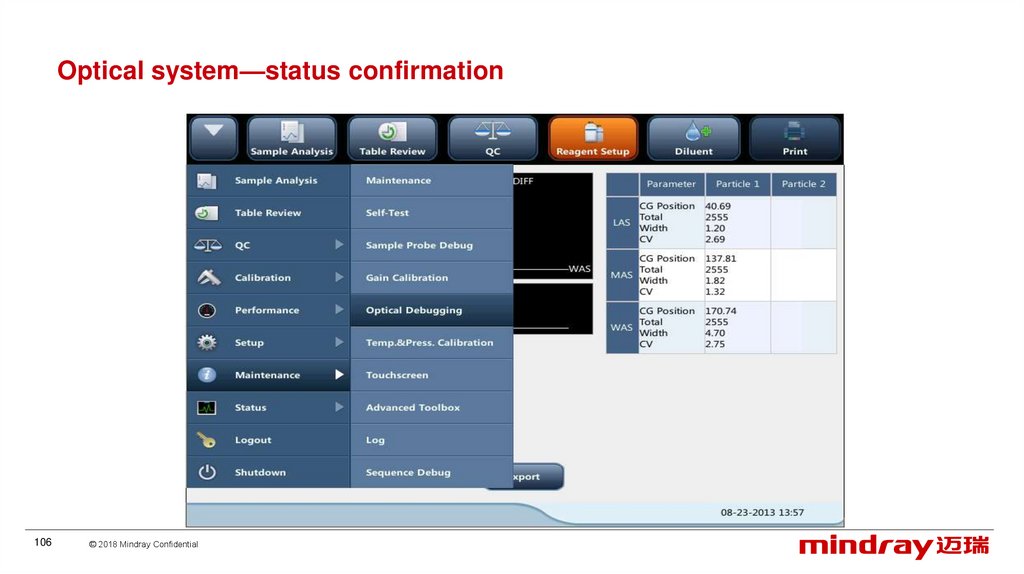
Optical system—status confirmationTo confirm the performance of optical system,
CG position-intensity of the signal
CV-signal stability
Enter the “optical” screen, perform counting with 7um standard particle solution (0.5ml
deionized water+3drops standard particle
Parameter
Total
LAS
MAS
WAS
105
© 2018 Mindray Confidential
1500~3000
CG Position
CV
38~42
≤6.50
107~158
≤3.00
135~220
≤8.00
106.
Optical system—status confirmation106
© 2018 Mindray Confidential
107.
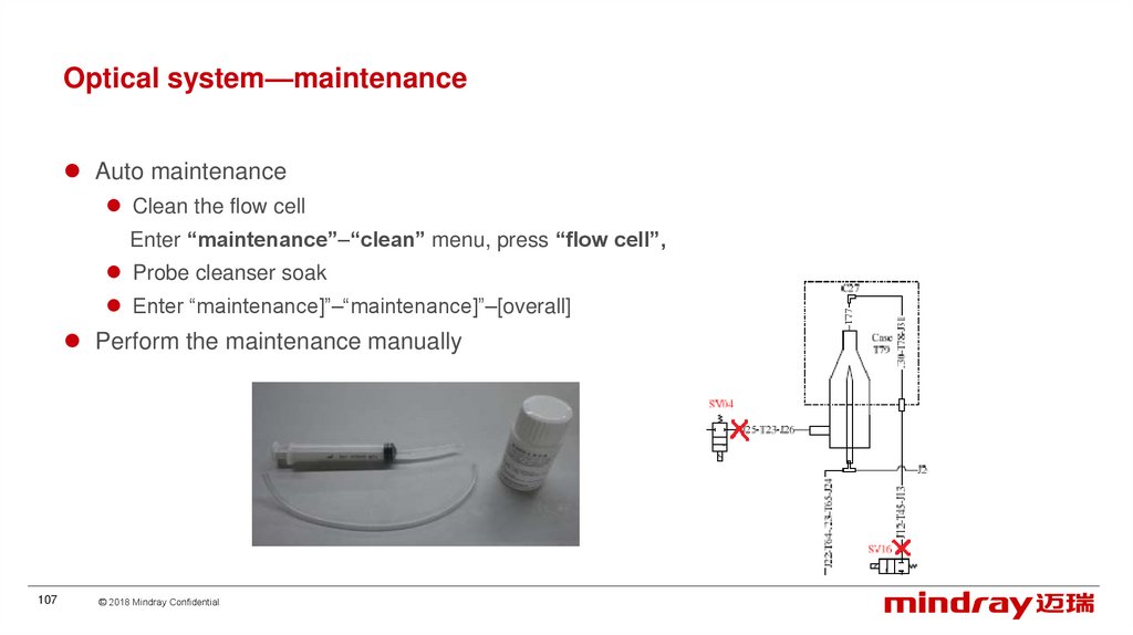
Optical system—maintenanceAuto maintenance
Clean the flow cell
Enter “maintenance”–“clean” menu, press “flow cell”,
Probe cleanser soak
Enter “maintenance]”–“maintenance]”–[overall]
Perform the maintenance manually
107
© 2018 Mindray Confidential
108.
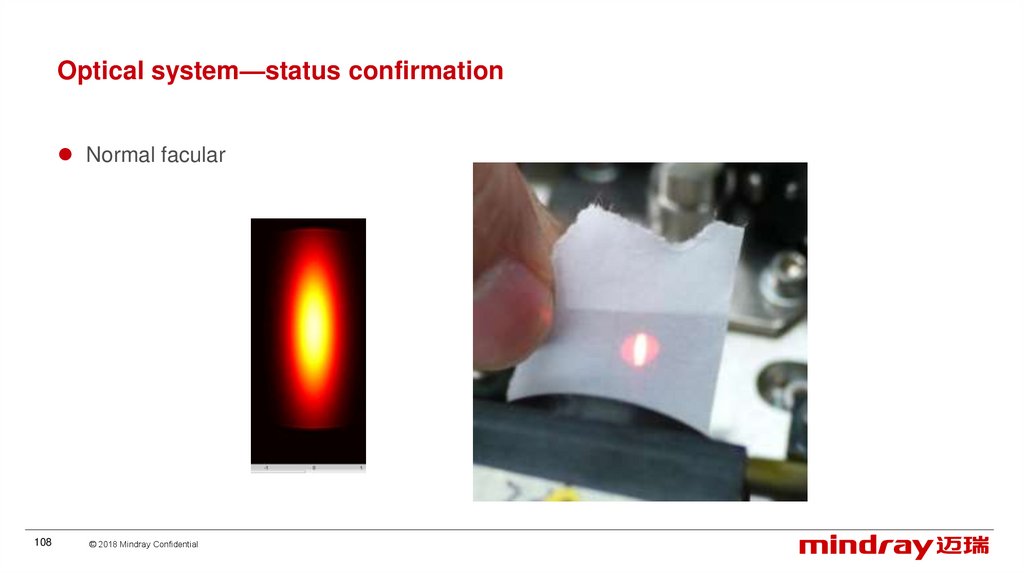
Optical system—status confirmationNormal facular
108
© 2018 Mindray Confidential
109.
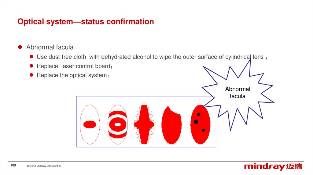
Optical system—status confirmationAbnormal facula
Use dust-free cloth with dehydrated alcohol to wipe the outer surface of cylindrical lens
Replace laser control board
Replace the optical system
Abnormal
facula
109
© 2018 Mindray Confidential
110.
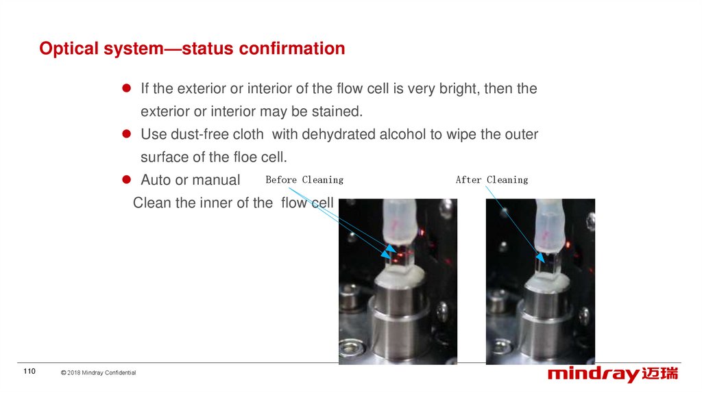
Optical system—status confirmationIf the exterior or interior of the flow cell is very bright, then the
exterior or interior may be stained.
Use dust-free cloth with dehydrated alcohol to wipe the outer
surface of the floe cell.
Auto or manual
Before Cleaning
Clean the inner of the flow cell
110
© 2018 Mindray Confidential
After Cleaning
111.
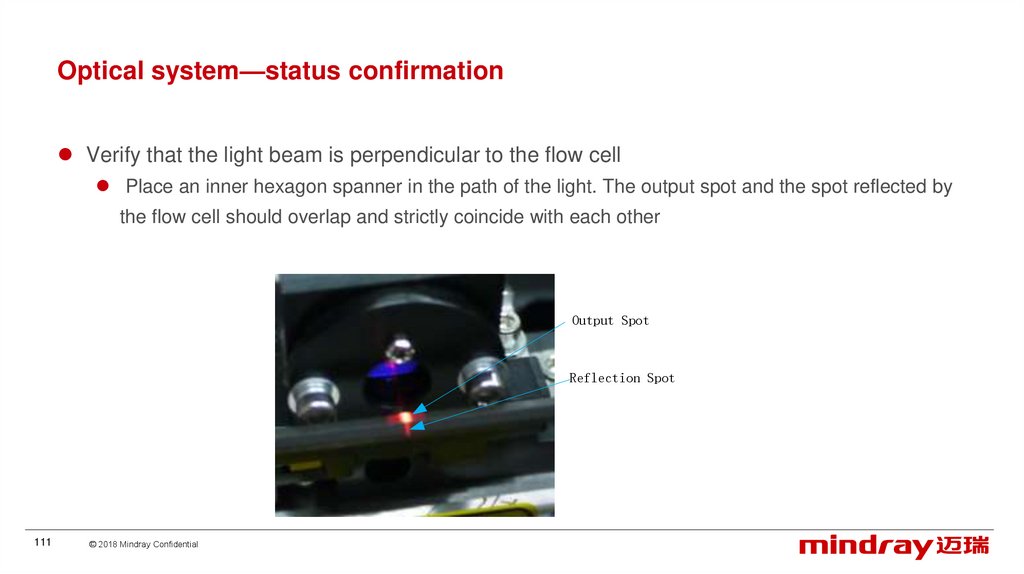
Optical system—status confirmationVerify that the light beam is perpendicular to the flow cell
Place an inner hexagon spanner in the path of the light. The output spot and the spot reflected by
the flow cell should overlap and strictly coincide with each other
Output Spot
Reflection Spot
111
© 2018 Mindray Confidential
112.
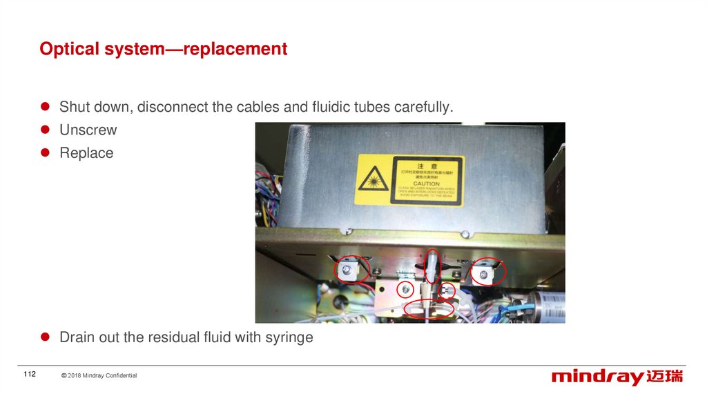
Optical system—replacementShut down, disconnect the cables and fluidic tubes carefully.
Unscrew
Replace
Drain out the residual fluid with syringe
112
© 2018 Mindray Confidential
113.
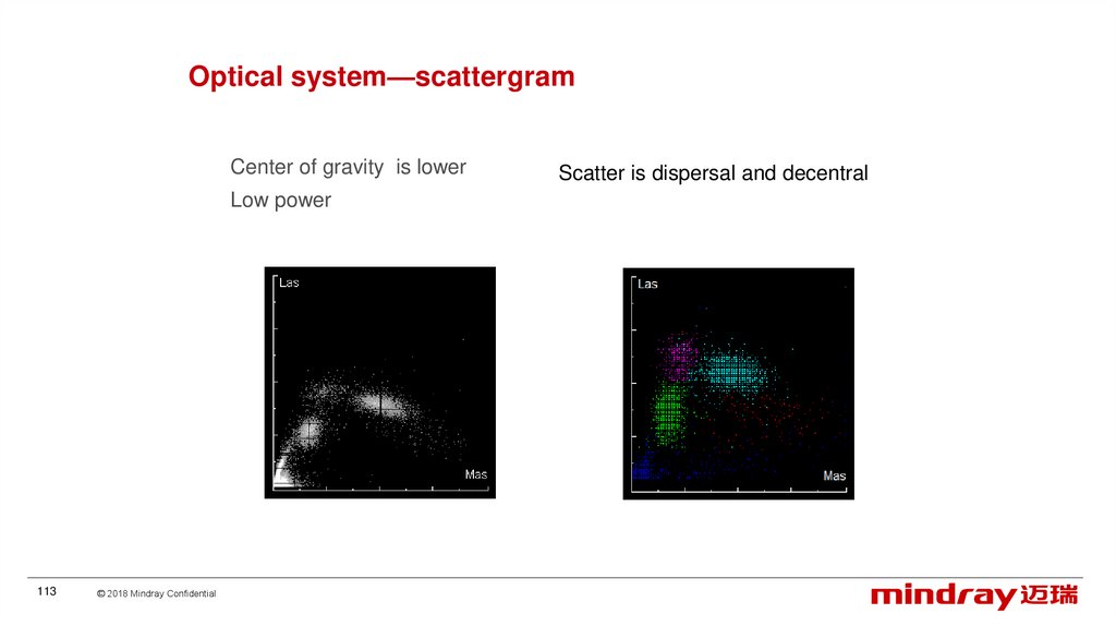
Optical system—scattergramCenter of gravity is lower
Low power
113
© 2018 Mindray Confidential
Scatter is dispersal and decentral
114.
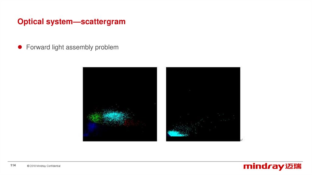
Optical system—scattergramForward light assembly problem
114
© 2018 Mindray Confidential
115.
ContentClinics
Overview
Principle
Installation
Software
Hardware
Optical system
Liquid system
Mechanical structure
115
© 2018 Mindray Confidential
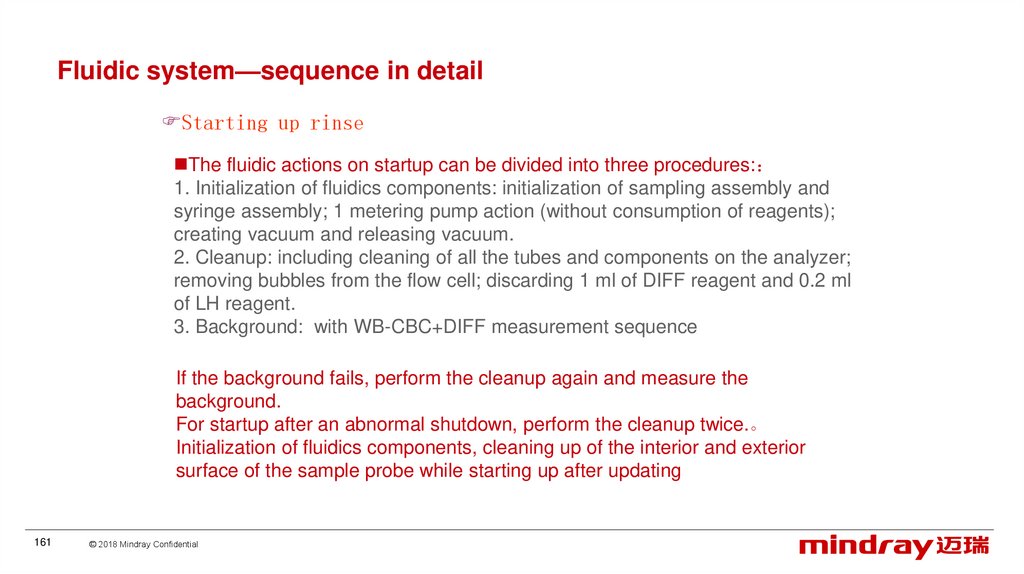
116.
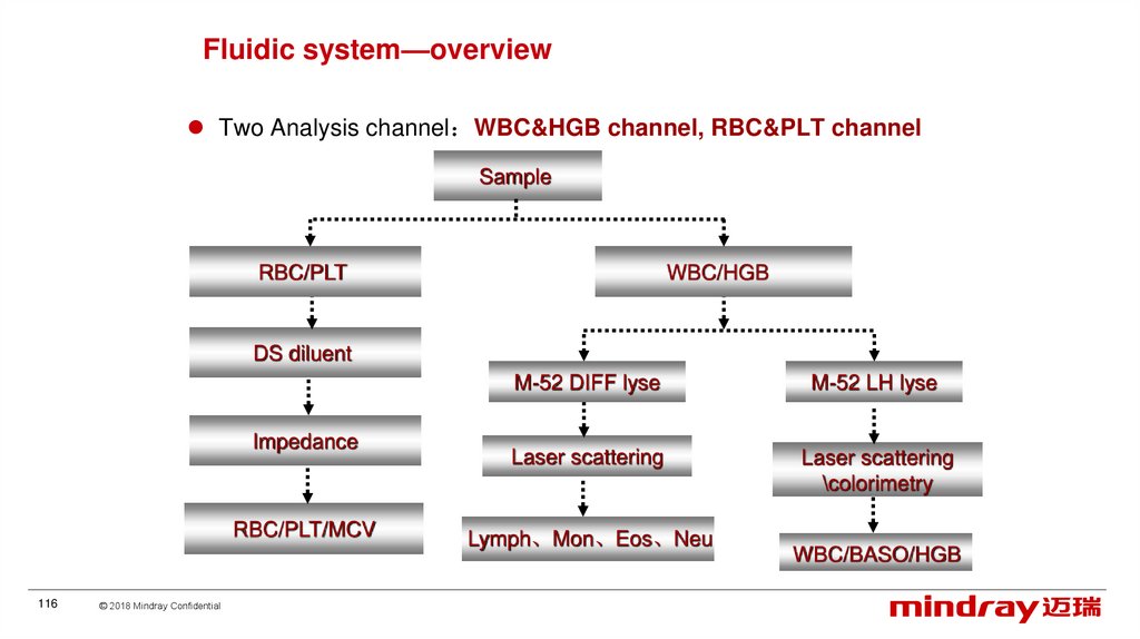
Fluidic system—overviewTwo Analysis channel WBC&HGB channel, RBC&PLT channel
Sample
RBC/PLT
WBC/HGB
DS diluent
Impedance
RBC/PLT/MCV
116
© 2018 Mindray Confidential
M-52 DIFF lyse
M-52 LH lyse
Laser scattering
Laser scattering
\colorimetry
Lymph、Mon、Eos、Neu
WBC/BASO/HGB
117.
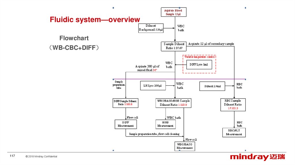
Fluidic system—overviewFlowchart
WB-CBC+DIFF
117
© 2018 Mindray Confidential
118.
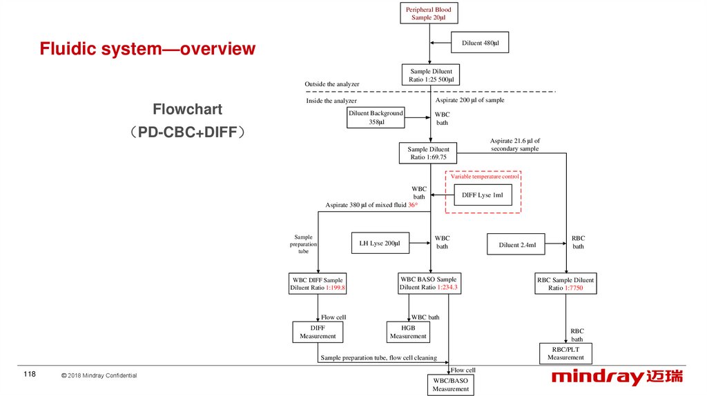
Peripheral BloodSample 20μl
Diluent 480μl
Fluidic system—overview
Sample Diluent
Ratio 1:25 500μl
Outside the analyzer
Flowchart
Aspirate 200 μl of sample
Inside the analyzer
Diluent Background
358μl
PD-CBC+DIFF
WBC
bath
Aspirate 21.6 μl of
secondary sample
Sample Diluent
Ratio 1:69.75
Variable temperature control
WBC
bath
Aspirate 380 μl of mixed fluid 36°
Sample
preparation
tube
WBC
bath
LH Lyse 200μl
WBC DIFF Sample
Diluent Ratio 1:199.8
Flow cell
DIFF
Measurement
DIFF Lyse 1ml
Diluent 2.4ml
WBC BASO Sample
Diluent Ratio 1:234.3
© 2018 Mindray Confidential
RBC Sample Diluent
Ratio 1:7750
WBC bath
HGB
Measurement
RBC
bath
RBC/PLT
Measurement
Sample preparation tube, flow cell cleaning
118
RBC
bath
Flow cell
WBC/BASO
Measurement
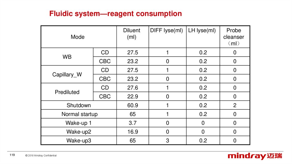
119.
Fluidic system—reagent consumptionDiluent
(ml)
Mode
27.5
1
0.2
0
CBC
23.2
0
0.2
0
CD
27.5
1
0.2
0
CBC
23.2
0
0.2
0
CD
27.6
1
0.2
0
CBC
22.9
0
0.2
0
Shutdown
60.9
1
0.2
2
Normal startup
65
1
0.2
0
Wake-up 1
3.7
0
0
0
Wake-up2
16.9
0
0
0
Wake-up3
65
3
0.2
0
Capillary_W
Prediluted
© 2018 Mindray Confidential
Probe
cleanser
ml
CD
WB
119
DIFF lyse(ml) LH lyse(ml)
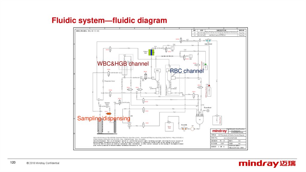
120.
Fluidic system—fluidic diagram2
3
4
5
REV
SV08
Yang Yijie
3.0
CR-3107-047
Yang Yijie
T20
DILUENT
T71
T72
T54
J18-T60-J19
DIFF Reagent Bottle
T41
Transducer
T58
SV10
T67
T66
T43
T73
SPB
VC
SV09
T44
WASTE
Waste
Tank
C25
Diluent Tank
Sampling/dispensing
J1-T4-J2
C8
T57
J27-T22-J28
J3-T5
T2
T1
SV03
C16
T46
J4-T6
C1
C7
T16
SV15
J5-T7-J6-T8
T56
T53
T42
C2
C26
T74
Hydraulic
Sensor
T39
C9
T36
SV11
T11
T10
C3
SV13
T38
T37
T55
T15
T14
C20
C21
SV12
C13
T62
T40
C5
T13
T51
C6
C12
T61
SV14
LH Reagent Bottle
T29
J9
T52
T33
Isolation Chamber 2
Case
T75
C10
J16-T59-J17
Isolation Chamber 1
SV16
T34
J10-T35-J11
J12-T45-J13
J22-T64-J23-T65-J24
T3
T9
SV06
T12
T24
T26
J30-T78-J31
T18
T77
T17
J20-T63-J21
C11
C18
C19
RBC channel
RBC
WBC
PV18
J25-T23-J26
C4
T47
SV07
SV04
Temperature Sensor
T50
SV02 DP2
WBC&HGB channel
B
C15
DP1
J14-T48-J15-T80-J32
Case
T79
C23
T49
SV01
T32
C27
C22
T30
J7-T31-J8
SV05
Preheat
Bath
Add T80,J32 and revise T48,J15
LF
T76
T25
CV1
J29
LP
C24
T69
Confidential classification:
Confidential
CONFIDENTIAL
T68
SR
D
TITLE
保密:此图及其全部知识产权(含著作权)归深圳迈瑞生物医疗电子股份有限公司所有。未经深圳迈瑞生物医疗电子股份有限公司预先书面许可,严禁出于任何目的,对
此图的全部或部分内容(包括但不限于图中信息、数据、运算结果等)泄露、使用、拷贝或复制。
Classified documents, This set of drawing(s) and all it's intellectual property rights (including copyright) subsisting herein are property of
Shenzhen Mindray Bio-medical Electronics Co.,Ltd. No disclosure,use,copies or reproductions should be made of this drawing or any part(s)
thereof for whatever purpose nor shall any information, data, calculations, or other contents contained in this drawing be disseminated without
prior written permission of Shenzhen Mindray Bio-medical Electronics Co.,Ltd
120
© 2018 Mindray Confidential
DESIGN
2.0
C14
T21
C
DESCRIPTION
Add the information of LF, T76 and tubes in the optical assembly, Revise T3,
CR-3107-042 T10, T11, T18, T20, T22, T32, T44, T57, T66, T70, T71, T75, C18, C19,
C20, C21
C17
T19
A
6
ECN
T70
1
MRSZ/R05N01.291.02 2.0
DOC No.
3107 Pneumatic & Fluidics System Diagram
A1-115-015670-00
DESIGN
杨一杰
REV.
P.CODE
3107
SHEET
1 OF 6
A4
SIZE
Software &Rev:
Microsoft visio 2003
3.0
121.
Fluidic system—componentHighly integrated air and hydraulic system
17valves 1 high pressure (2-way)(V3);1pinch valve(V18)、1LVM(V11)
1 syringe assembly (2 syringes 250ul、10ml
1 sampling assembly
2 Electromagnetic Metering pumps 1ml、200ul
2 counting baths
2 isolate chambers
1 flow cell
1 waster pump
1 preheat bath assembly
1 hydraulic pressure sensor
1 check valve
1 filter
1 vacuum chamber
121
© 2018 Mindray Confidential
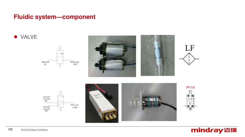
122.
Fluidic system—componentVALVE
122
© 2018 Mindray Confidential
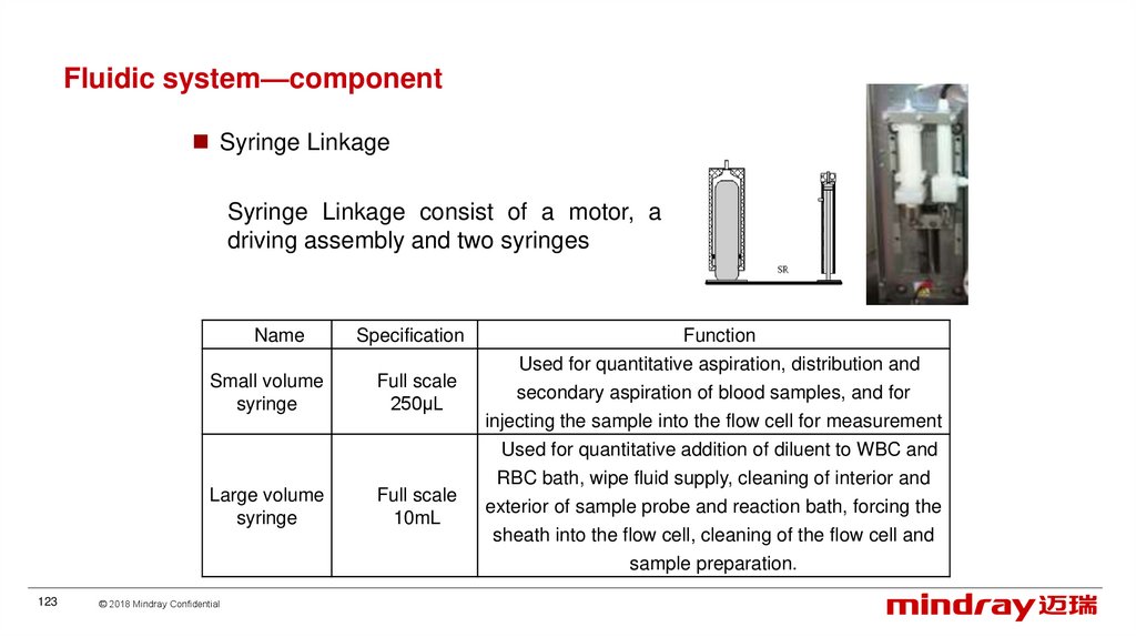
123.
Fluidic system—componentSyringe Linkage
Syringe Linkage consist of a motor, a
driving assembly and two syringes
Name
Specification
Small volume
syringe
Full scale
250μL
Function
Used for quantitative aspiration, distribution and
secondary aspiration of blood samples, and for
injecting the sample into the flow cell for measurement
Used for quantitative addition of diluent to WBC and
Large volume
syringe
Full scale
10mL
RBC bath, wipe fluid supply, cleaning of interior and
exterior of sample probe and reaction bath, forcing the
sheath into the flow cell, cleaning of the flow cell and
sample preparation.
123
© 2018 Mindray Confidential
124.
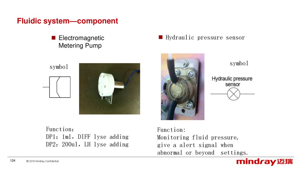
Fluidic system—componentElectromagnetic
Metering Pump
symbol
Function
DP1 1ml DIFF lyse adding
DP2 200ul LH lyse adding
124
© 2018 Mindray Confidential
Hydraulic pressure sensor
symbol
Function:
Monitoring fluid pressure,
give a alert signal when
abnormal or beyond settings.
125.
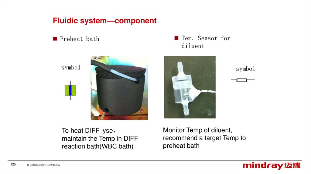
Fluidic system—componentPreheat bath
symbol
To heat DIFF lyse
maintain the Temp in DIFF
reaction bath(WBC bath)
125
© 2018 Mindray Confidential
Tem. Sensor for
diluent
symbol
Monitor Temp of diluent,
recommend a target Temp to
preheat bath
126.
Fluidic system—componentFluidic temperature control
Item
Preheat bath
Target
Temp
Refer to diluent
Alarm
Temp
<target Temp -1.5
>target Temp +3
diluent
<10, >40
Diluent
Temperature
Sensor
J10
Analog Drive
J21
Board
126
© 2018 Mindray Confidential
Reaction Bath
Temperature
Sensor
PIN1
Temperature
Temperature
Switch
Switch
PIN3
Preheat
Preheat
assembly
assembly
127.
Fluidic system—componentWaste pump
Drain the wipe block, WBC bath,
RBC bath and vacuum chamber,
create vacuum in the vacuum
chamber
127
© 2018 Mindray Confidential
Check valve
Define the flow direction of
DIFF lyse in case of reverse
flow
Attention : direction
128.
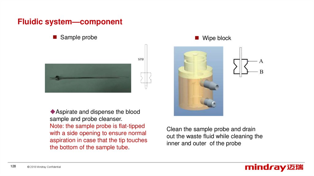
Fluidic system—componentSample probe
Aspirate and dispense the blood
sample and probe cleanser.
Note: the sample probe is flat-tipped
with a side opening to ensure normal
aspiration in case that the tip touches
the bottom of the sample tube.
128
© 2018 Mindray Confidential
Wipe block
Clean the sample probe and drain
out the waste fluid while cleaning the
inner and outer of the probe
129.
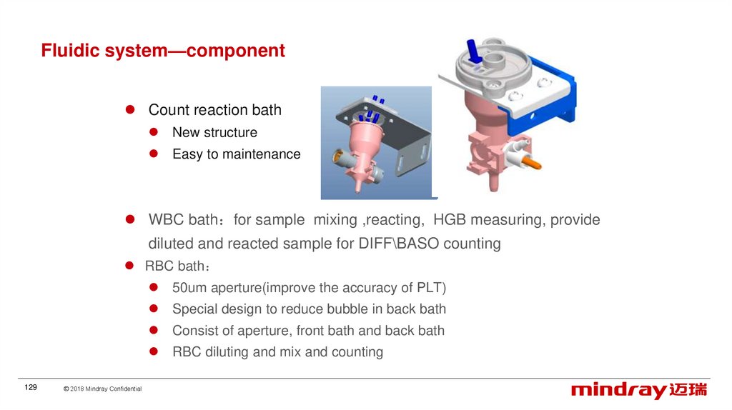
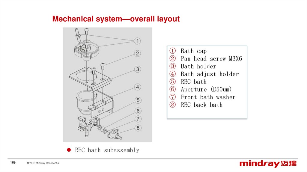
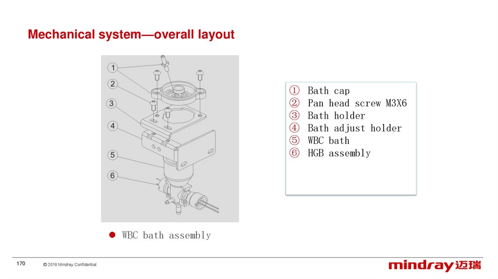
Fluidic system—componentCount reaction bath
New structure
Easy to maintenance
WBC bath for sample mixing ,reacting, HGB measuring, provide
diluted and reacted sample for DIFF\BASO counting
RBC bath
50um aperture(improve the accuracy of PLT)
Special design to reduce bubble in back bath
Consist of aperture, front bath and back bath
RBC diluting and mix and counting
129
© 2018 Mindray Confidential
130.
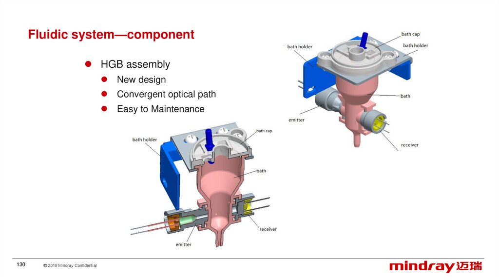
Fluidic system—componentHGB assembly
New design
Convergent optical path
Easy to Maintenance
130
© 2018 Mindray Confidential
131.
Fluidic system—componentVacuum chamber maintain negative pressure for RBC counting. Same with that of BC3000
WBC/RBC Isolation chamber : provide an isolation air room to cut off the internal or external
interference
131
© 2018 Mindray Confidential
132.
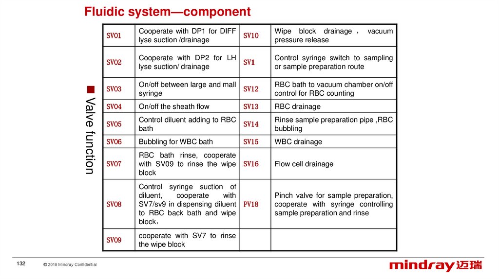
Fluidic system—componentValve function
132
© 2018 Mindray Confidential
SV01
Cooperate with DP1 for DIFF
lyse suction /drainage
SV10
Wipe block drainage vacuum
pressure release
SV02
Cooperate with DP2 for LH
lyse suction/ drainage
SV11
Control syringe switch to sampling
or sample preparation route
SV03
On/off between large and mall
syringe
SV12
RBC bath to vacuum chamber on/off
control for RBC counting
SV04
On/off the sheath flow
SV13
RBC drainage
SV05
Control diluent adding to RBC
bath
SV14
Rinse sample preparation pipe ,RBC
bubbling
SV06
Bubbling for WBC bath
SV15
WBC drainage
SV07
RBC bath rinse, cooperate
with SV09 to rinse the wipe
block
SV16
Flow cell drainage
SV08
Control syringe suction of
diluent,
cooperate
with
SV7/sv9 in dispensing diluent
to RBC back bath and wipe
block
PV18
Pinch valve for sample preparation,
cooperate with syringe controlling
sample preparation and rinse
SV09
cooperate with SV7 to rinse
the wipe block
133.
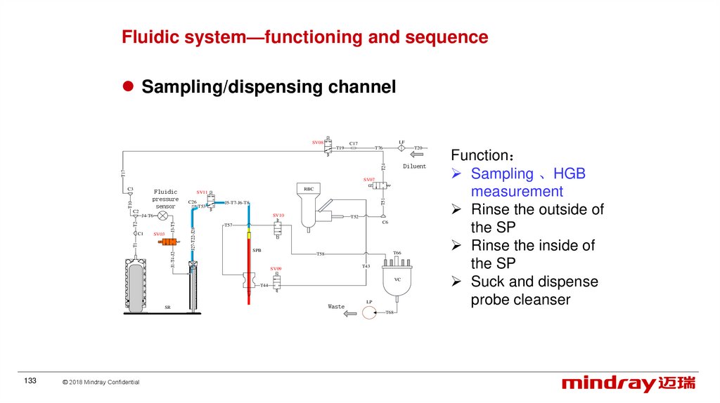
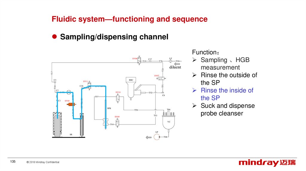
Fluidic system—functioning and sequenceSampling/dispensing channel
SV08
LF
C17
T76
T20
Diluent
T17
T24
T19
SV07
T10
Fluidic
pressure
sensor
RBC
SV11
C26
T53
T51
C3
J5-T7-J6-T8
C2
SV10
SV03
J1-T4-J2
T1
C1
T52
C6
T57
J27-T22-J28
T2
J3-T5
J4-T6
SPB
T66
T58
T43
SV09
VC
T44
SR
Waste
LP
T68
133
© 2018 Mindray Confidential
Function
Sampling 、HGB
measurement
Rinse the outside of
the SP
Rinse the inside of
the SP
Suck and dispense
probe cleanser
134.
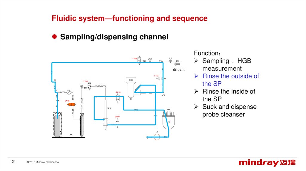
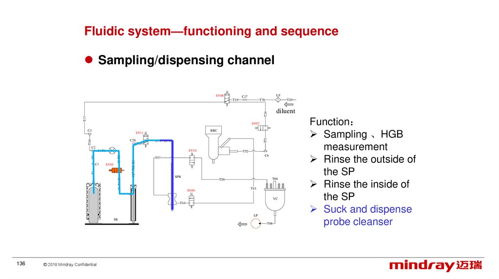
Fluidic system—functioning and sequenceSampling/dispensing channel
SV08
LF
C17
T76
T20
diluent
T17
T24
T19
SV07
C3
RBC
T10
C26
T53
T51
SV11
J5-T7-J6-T8
C2
SV10
SV03
J1-T4-J2
T1
C1
T52
C6
T57
J27-T22-J28
T2
J3-T5
J4-T6
SPB
T66
T58
SV09
T43
VC
T44
LP
SR
T68
134
© 2018 Mindray Confidential
Function
Sampling 、HGB
measurement
Rinse the outside of
the SP
Rinse the inside of
the SP
Suck and dispense
probe cleanser
135.
Fluidic system—functioning and sequenceSampling/dispensing channel
SV08
LF
C17
T76
T20
diluent
T17
T24
T19
SV07
C3
RBC
T10
C26
T53
T51
SV11
J5-T7-J6-T8
C2
SV10
SV03
J1-T4-J2
T1
C1
T52
C6
T57
J27-T22-J28
T2
J3-T5
J4-T6
SPB
T66
T58
SV09
T43
VC
T44
LP
SR
T68
135
© 2018 Mindray Confidential
Function
Sampling 、HGB
measurement
Rinse the outside of
the SP
Rinse the inside of
the SP
Suck and dispense
probe cleanser
136.
Fluidic system—functioning and sequenceSampling/dispensing channel
SV08
LF
C17
T76
T20
diluent
T17
T24
T19
SV07
C3
RBC
T10
C26
T53
T51
SV11
J5-T7-J6-T8
C2
SV10
SV03
J1-T4-J2
T1
C1
T52
C6
T57
J27-T22-J28
T2
J3-T5
J4-T6
SPB
T66
T58
SV09
T43
VC
T44
LP
SR
T68
136
© 2018 Mindray Confidential
Function
Sampling 、HGB
measurement
Rinse the outside of
the SP
Rinse the inside of
the SP
Suck and dispense
probe cleanser
137.
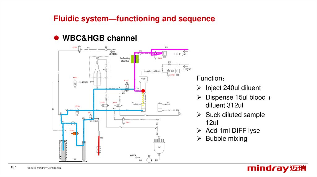
Fluidic system—functioning and sequenceWBC&HGB channel
SV08
LF
C17
T19
T76
C14
T20
diluent
DIFF lyse
SV01
T32
DP1
C15
J30-T78-J31
T50
T26
T77
T17
T49
T30
J7-T31-J8
J29
Preheating
chamber
C27
T9
T25
CV1
J14-T48-J15-T80-J32
LH lyse
T47
SV02 DP2
SV16
T34
外套
T75
C10
T33
C12
T61
SV14
C13
T62
C5
T13
T12
C11
J10-T35-J11
J22-T64-J23-T65-J24
T9
SV06
C4
J12-T45-J13
J20-T63-J21
J16-T59-J17
PV18
J25-T23-J26
WBC
J9
SV04
T14
T37
SV11
T15
C3
T11
T16
J5-T7-J6-T8
J1-T4-J2
T46
C8
T42
J27-T22-J28
J3-T5
T2
SV03
T1
C1
C7
SV15
J4-T6
T41
T10
T53
C2
C9
T36
C26
T66
SPB
VC
Waste
SR
137
© 2018 Mindray Confidential
LP
T69
T38
T68
Function
Inject 240ul diluent
Dispense 15ul blood +
diluent 312ul
Suck diluted sample
12ul
Add 1ml DIFF lyse
Bubble mixing
138.
Fluidic system—functioning and sequenceWBC&HGB channel
SV08
LF
C17
T19
T76
C14
T20
diluent
T17
DIFF lyse
SV01
T32
DP1
C15
J30-T78-J31
T50
T26
T77
Perheating
chamber
T49
T30
J7-T31-J8
J29
C27
T79
T25
CV1
J14-T48-J15-T80-J32
LH lyse
T47
SV02 DP2
PV18
J25-T23-J26
C10
T33
T75
C12
T61
SV14
C13
T62
C5
T13
T12
T34
J16-T59-J17
SV16
C11
J10-T35-J11
J22-T64-J23-T65-J24
T9
SV06
C4
J12-T45-J13
J20-T63-J21
WBC
J9
SV04
T14
T37
SV11
T15
C3
T11
C2
T53
T16
J5-T7-J6-T8
J1-T4-J2
T46
C8
T42
J27-T22-J28
J3-T5
T2
T1
SV03
C7
SV15
J4-T6
C1
C9
T36
C26
T41
T10
Fluidic
pressure
sensor
T66
SPB
VC
Waste
SR
138
© 2018 Mindray Confidential
T69
T38
LP
T68
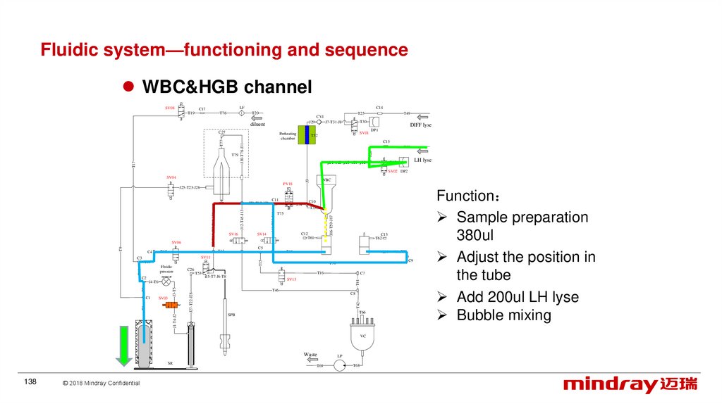
Function
Sample preparation
380ul
Adjust the position in
the tube
Add 200ul LH lyse
Bubble mixing
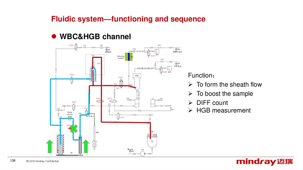
139.
Fluidic system—functioning and sequenceWBC&HGB channel
SV08
LF
C17
T19
T76
C14
T20
C27
T17
DIFF lyse
SV01
T32
DP1
C15
J30-T78-J31
T50
T26
T77
Preheating
chamber
T49
T30
J7-T31-J8
J29
diluent
T79
T25
CV1
LH lyse
J14-T48-J15-T80-J32
T47
SV02 DP2
SV16
T34
T75
C10
T33
C12
T61
SV14
C13
T62
C5
T13
T12
C11
J10-T35-J11
J22-T64-J23-T65-J24
T9
SV06
C4
J12-T45-J13
J20-T63-J21
J16-T59-J17
PV18
J25-T23-J26
WBC
J9
SV04
T14
T37
SV11
T15
C3
T11
C2
T53
T16
J5-T7-J6-T8
J1-T4-J2
T46
C8
T42
J27-T22-J28
J3-T5
T2
T1
SV03
C7
SV15
J4-T6
C1
C9
T36
C26
T41
T10
Fluidic
pressure
sensor
T66
SPB
VC
Waste
SR
139
© 2018 Mindray Confidential
T69
T38
LP
T68
Function
To form the sheath flow
To boost the sample
DIFF count
HGB measurement
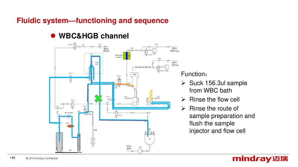
140.
Fluidic system—functioning and sequenceWBC&HGB channel
SV08
LF
C17
T19
T76
C14
T20
C27
T17
DIFF lyse
SV01
T32
DP1
C15
J30-T78-J31
T50
T26
T77
Preheating
chamber
T49
T30
J7-T31-J8
J29
diluent
外套
T79
T25
CV1
LH lyse
J14-T48-J15-T80-J32
T47
SV02 DP2
SV16
T34
外套
T75
C10
T33
C12
T61
SV14
隔
离
室
1
C5
T13
T12
C11
J10-T35-J11
J22-T64-J23-T65-J24
T9
SV06
C4
J12-T45-J13
J20-T63-J21
J16-T59-J17
PV18
J25-T23-J26
WBC
J9
SV04
T14
C13
T62
隔
离
室
2
T37
SV11
T15
C3
液压传感器
T53
C2
T16
J5-T7-J6-T8
J1-T4-J2
T46
C8
T42
J27-T22-J28
J3-T5
T2
SV03
T1
C1
C7
SV15
J4-T6
T66
SPB
VC
废液
SR
140
© 2018 Mindray Confidential
T69
T38
C9
T36
C26
T41
T10
T11
LP
T68
Function
Suck 156.3ul sample
from WBC bath
Rinse the flow cell
Rinse the route of
sample preparation and
flush the sample
injector and flow cell
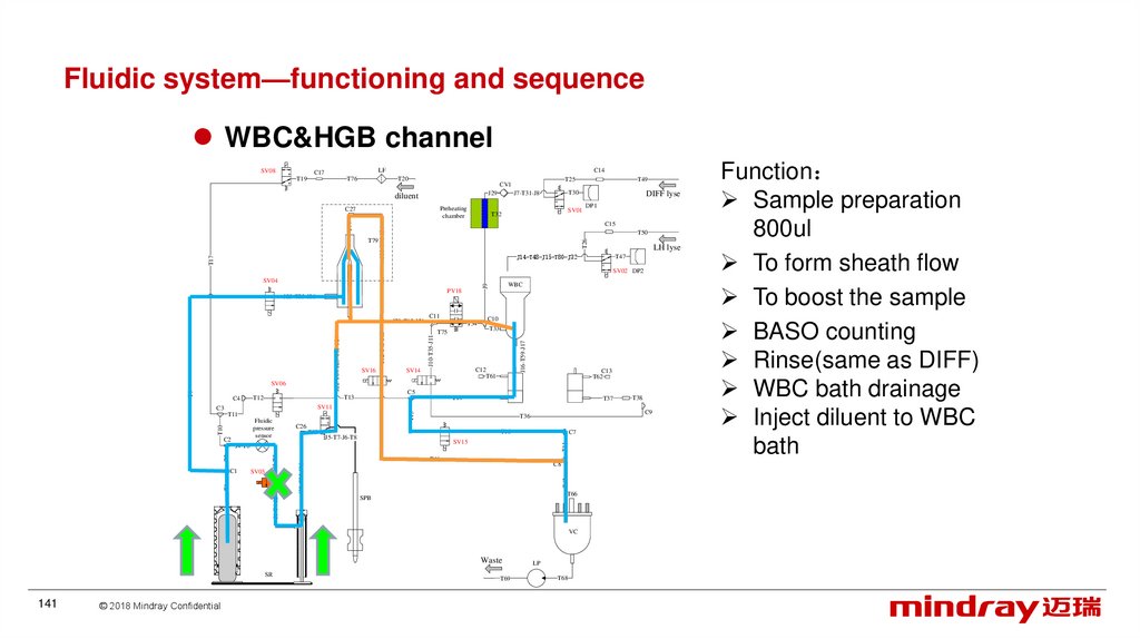
141.
Fluidic system—functioning and sequenceWBC&HGB channel
SV08
LF
C17
T19
T76
C14
T20
diluent
Preheating
chamber
DIFF lyse
SV01
T32
DP1
C15
J30-T78-J31
T50
T26
T77
T17
T49
T30
J7-T31-J8
J29
C27
T79
T25
CV1
LH lyse
J14-T48-J15-T80-J32
T47
SV02 DP2
SV16
T34
T75
C10
T33
C12
T61
SV14
C13
T62
C5
T13
T12
C11
J10-T35-J11
J22-T64-J23-T65-J24
T9
SV06
C4
J12-T45-J13
J20-T63-J21
J16-T59-J17
PV18
J25-T23-J26
WBC
J9
SV04
T14
T37
SV11
T15
C3
T11
C2
T53
T16
J5-T7-J6-T8
J1-T4-J2
T46
C8
T42
J27-T22-J28
J3-T5
T2
T1
SV03
C7
SV15
J4-T6
C1
C9
T36
C26
T41
T10
Fluidic
pressure
sensor
T66
SPB
VC
Waste
SR
141
© 2018 Mindray Confidential
T69
T38
LP
T68
Function
Sample preparation
800ul
To form sheath flow
To boost the sample
BASO counting
Rinse(same as DIFF)
WBC bath drainage
Inject diluent to WBC
bath
142.
Fluidic system—functioning and sequenceWBC&HGB channel
SV08
LF
C17
T19
T76
C14
T20
C27
T17
DIFF lyse
SV01
T32
DP1
C15
J30-T78-J31
T50
T26
T77
Reheating
chamber
T49
T30
J7-T31-J8
J29
diluent
T79
T25
CV1
LH lyse
J14-T48-J15-T80-J32
T47
SV02 DP2
SV16
T34
T75
C10
T33
C12
T61
SV14
C13
T62
C5
T13
T12
C11
J10-T35-J11
J22-T64-J23-T65-J24
T9
SV06
C4
J12-T45-J13
J20-T63-J21
J16-T59-J17
PV18
J25-T23-J26
WBC
J9
SV04
T14
T37
SV11
T15
C3
T11
C2
T53
T16
J5-T7-J6-T8
J1-T4-J2
T46
C8
T42
J27-T22-J28
J3-T5
T2
T1
SV03
C7
SV15
J4-T6
C1
C9
T36
C26
T41
T10
Fluidic
pressure
sensor
T66
SPB
VC
Waste
SR
142
© 2018 Mindray Confidential
T69
T38
LP
T68
Function
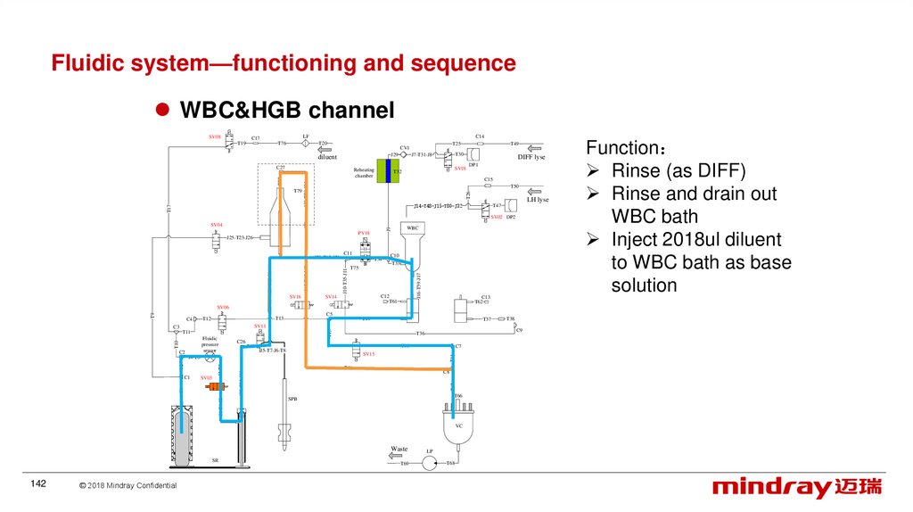
Rinse (as DIFF)
Rinse and drain out
WBC bath
Inject 2018ul diluent
to WBC bath as base
solution
143.
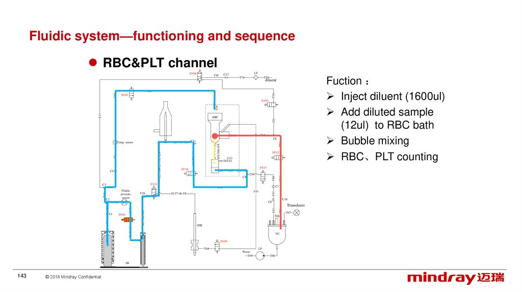
Fluidic system—functioning and sequenceRBC&PLT channel
SV08
LF
C17
T19
T76
Fuction
Inject diluent (1600ul)
Add diluted sample
(12ul) to RBC bath
Bubble mixing
RBC、PLT counting
T20
diluent
T24
T18
T21
SV05
T17
T29
SV07
T51
RBC
T52
T54
J18-T60-J19
J10-T35-J11
SV12
C13
T62
SV13
T37
T38
C9
T39
SV11
T11
T53
T43
J5-T7-J6-T8
T41
C26
C16
C8
SV03
J1-T4-J2
T1
T42
C1
Transducer
J27-T22-J28
T2
J3-T5
J4-T6
T66
SPB
VC
SV09
T44
LP
Waste
T69
SR
143
© 2018 Mindray Confidential
T56
T10
C2
C7
T36
Fluidic
pressure
sensor
T55
SV14
T40
J22-T64-J23-T65-J24
T3
C4
C3
C6
J20-T63-J21 C11
Temp. sensor
T68
T67
144.
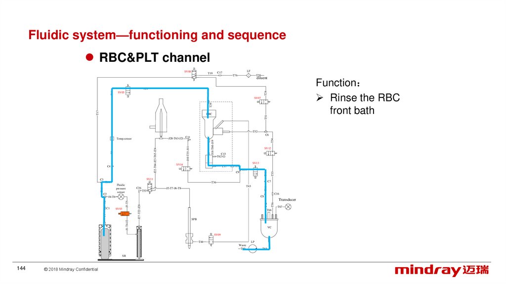
Fluidic system—functioning and sequenceRBC&PLT channel
SV08
LF
C17
T19
T76
T20
diluent
Function
Rinse the RBC
front bath
T24
T18
T21
SV05
T17
T29
SV07
T51
RBC
T52
T54
J18-T60-J19
J10-T35-J11
SV12
C13
T62
SV13
T37
T38
C9
T39
SV11
T11
T53
T43
J5-T7-J6-T8
T41
C26
C16
C8
SV03
J1-T4-J2
T1
T42
C1
Transducer
J27-T22-J28
T2
J3-T5
J4-T6
T66
SPB
VC
SV09
T44
LP
Waste
T69
SR
144
© 2018 Mindray Confidential
T56
T10
C2
C7
T36
Fluidic
pressure
sensor
T55
SV14
T40
J22-T64-J23-T65-J24
T3
C4
C3
C6
J20-T63-J21 C11
Temp.sensor
T68
T67
145.
Fluidic system—functioning and sequenceRBC&PLT channel
SV08
LF
C17
T76
T20
diluent
T17
T24
T19
SV07
C3
RBC
T10
C2
C26
T53
T51
SV11
Fluidic
pressure
sensor
J5-T7-J6-T8
SV10
SV03
J1-T4-J2
T1
C1
T52
C6
T57
J27-T22-J28
T2
J3-T5
J4-T6
SPB
T66
T58
T43
SV09
VC
T44
LP
SR
Waste
T68
145
© 2018 Mindray Confidential
Function
Rinse the RBC
back bath
Inject diluent
(2560ul) to RBC
bath as base
solution
Release vacuum
146.
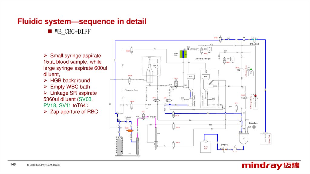
Fluidic system—sequence in detailWB_CBC+DIFF
SV08
LF
C17
T19
T76
T20
J29
T49
T30
J7-T31-J8
SV05
SV01
T52
T33
© 2018 Mindray Confidential
T72
T70
DIFF Reagent Bottle
T41
T67
T66
T43
VC
WASTE
Waste
Tank
C25
LP
C24
T69
T68
T73
SPB
T44
146
T42
SV10
T56
Transducer
T58
SV09
SR
T54
J18-T60-J19
C8
Diluent Tank
J1-T4-J2
C16
T46
T57
J27-T22-J28
J3-T5
T2
T1
SV03
C20
C21
C7
T16
SV15
J5-T7-J6-T8
J4-T6
C1
C9
T74
T10
T53
T39
T36
T11
C26
SV13
T38
T37
T55
T15
T14
SV12
C13
T62
T40
C5
Isolation Chamber 2
C6
SV11
C2
T51
C10
C12
T61
SV14
T13
T12
T34
Case
T75
J16-T59-J17
Isolation Chamber 1
SV16
C11
J10-T35-J11
T3
SV06
J12-T45-J13
J22-T64-J23-T65-J24
J20-T63-J21
Hydraulic
Sensor
RBC
WBC
C18
C19
T71
J9
T29
SV07
PV18
Temperature Sensor
LH Reagent Bottle
J30-T78-J31
T18
T77
T17
Case
T79
T47
SV02 DP2
J25-T23-J26
C3
T50
J14-T48-J15-T80-J32
SV04
C4
C15
DP1
T26
T32
C27
T9
Small syringe aspirate
15μL blood sample, while
large syringe aspirate 600ul
diluent,
HGB background
Empty WBC bath
Linkage SR aspirate
5360ul diluent (SV03、
PV18, SV11 toT64
Zap aperture of RBC
Preheat
Bath
T24
T21
C23
DILUENT
C14
T25
CV1
C22
147.
Fluidic system—sequence in detailSV08
LF
C17
T19
T76
T20
J29
T49
T30
J7-T31-J8
SV05
Preheat
Bath
T52
T33
VC
SV09
147
© 2018 Mindray Confidential
T70
T66
T43
SPB
T44
SR
T54
T41
SV10
T67
WASTE
Waste
Tank
C25
LP
C24
T69
T68
T73
J1-T4-J2
Transducer
T58
Diluent Tank
SV03
C8
T57
J27-T22-J28
J3-T5
T2
C1
C16
T46
J4-T6
C20
C21
C7
T16
SV15
J5-T7-J6-T8
T56
T53
C9
T42
C2
C26
T39
T74
Hydraulic
Sensor
SV13
T38
T37
T36
T11
DIFF Reagent Bottle
T15
T14
T55
C5
SV12
C13
T62
T40
C12
T61
SV14
T72
C6
SV11
T10
C3
T51
C10
Isolation Chamber 2
T34
Case
T75
J16-T59-J17
Isolation Chamber 1
C11
J10-T35-J11
T3
T9
SV16
T13
T12
T1
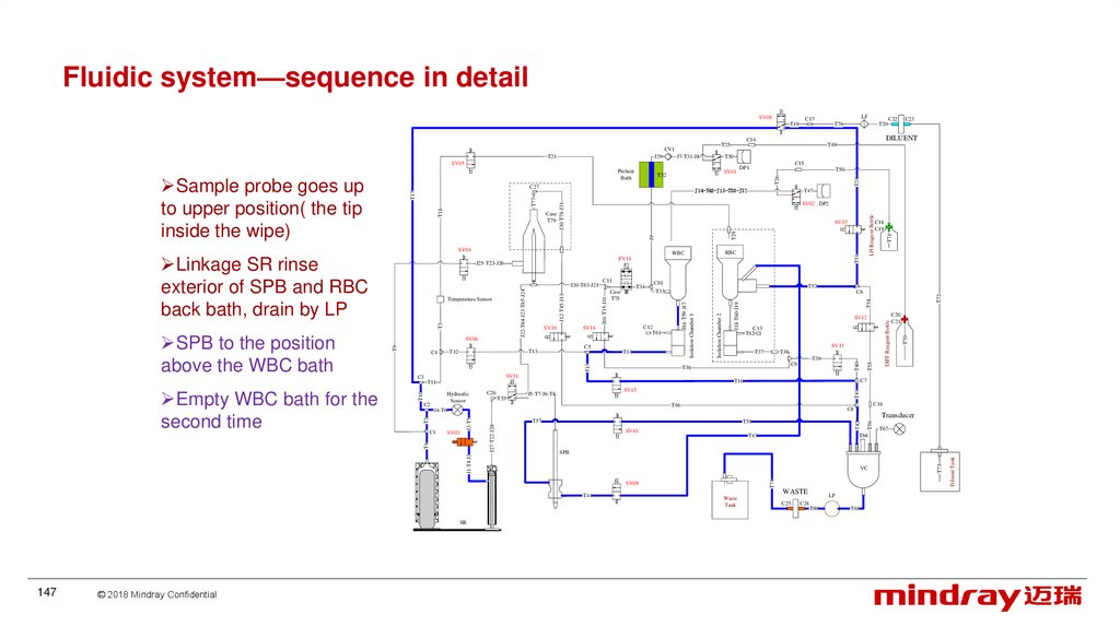
Empty WBC bath for the
second time
SV06
J12-T45-J13
J22-T64-J23-T65-J24
J20-T63-J21
C4
RBC
WBC
PV18
C18
C19
T71
J9
T29
SV07
J25-T23-J26
Temperature Sensor
LH Reagent Bottle
J30-T78-J31
T18
Case
T79
T47
SV02 DP2
SV04
SPB to the position
above the WBC bath
T50
J14-T48-J15-T80-J32
T77
T17
C27
Linkage SR rinse
exterior of SPB and RBC
back bath, drain by LP
C15
DP1
T26
T32
J18-T60-J19
Sample probe goes up
to upper position( the tip
inside the wipe)
SV01
T24
T21
C23
DILUENT
C14
T25
CV1
C22
148.
Fluidic system—sequence in detailvSV08
LF
C17
T19
T76
T20
T49
T30
J7-T31-J8
SV05
SV01
T52
T33
© 2018 Mindray Confidential
T72
T70
DIFF Reagent Bottle
T41
T67
T66
T43
VC
WASTE
Waste
Tank
C25
LP
C24
T69
T68
T73
SPB
T44
148
T42
T58
SV10
T56
Transducer
T57
SV09
SR
T54
J18-T60-J19
C8
Diluent Tank
J1-T4-J2
C16
T46
J27-T22-J28
J3-T5
T2
T1
SV03
C7
SV15
J5-T7-J6-T8
J4-T6
C1
C9
T16
T74
T10
T53
T39
T36
T11
C26
SV13
T38
T37
T55
T15
T14
C20
C21
SV12
C13
T62
T40
C5
Isolation Chamber 2
C6
SV11
C2
T51
C10
C12
T61
SV14
T13
T12
T34
Case
T75
J16-T59-J17
Isolation Chamber 1
SV16
C11
J10-T35-J11
T3
SV06
J12-T45-J13
J22-T64-J23-T65-J24
J20-T63-J21
Hydraulic
Sensor
RBC
WBC
PV18
C18
C19
T71
J9
T29
SV07
J25-T23-J26
Temperature Sensor
LH Reagent Bottle
J30-T78-J31
T18
Case
T79
T47
SV02 DP2
SV04
C3
T50
J14-T48-J15-T80-J32
T77
T17
C27
C4
C15
DP1
T26
T32
T24
Preheat
Bath
T9
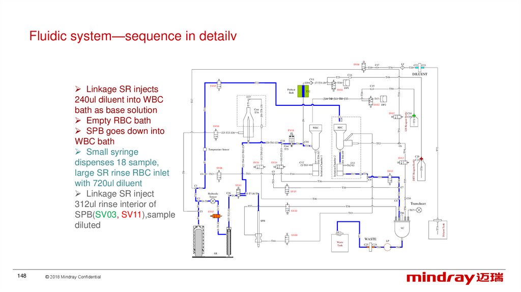
Linkage SR injects
240ul diluent into WBC
bath as base solution
Empty RBC bath
SPB goes down into
WBC bath
Small syringe
dispenses 18 sample,
large SR rinse RBC inlet
with 720ul diluent
Linkage SR inject
312ul rinse interior of
SPB(SV03, SV11),sample
diluted
J29
C23
DILUENT
C14
T25
CV1
T21
C22
149.
Fluidic system—sequence in detailSV08
J29
Preheat
Bath
SV01
T72
T54
DIFF Reagent Bottle
T41
C8
T42
SV10
T56
Transducer
T58
T67
T66
T43
VC
T44
WASTE
Waste
Tank
C25
LP
C24
T69
T68
T73
SPB
Diluent Tank
J1-T4-J2
C16
T46
SV09
© 2018 Mindray Confidential
C20
C21
C7
T16
SV15
J5-T7-J6-T8
T57
J27-T22-J28
J3-T5
T2
J18-T60-J19
T36
J4-T6
T1
T39
C9
T74
T10
T53
SV13
T38
T37
T55
T15
T14
SV12
C13
T62
T40
C5
Isolation Chamber 2
C6
C12
T61
SV14
T71
T52
T33
SV11
SR
T51
C10
J16-T59-J17
Isolation Chamber 1
T34
Case
T75
T11
C26
LH Reagent Bottle
T29
J9
C11
J10-T35-J11
J12-T45-J13
J22-T64-J23-T65-J24
T3
T9
SV16
T13
SV03
RBC
WBC
SV06
C1
C18
C19
SV07
PV18
T12
Hydraulic
Sensor
T47
SV02 DP2
J30-T78-J31
T18
T77
T17
Case
T79
Temperature Sensor
C3
T50
J14-T48-J15-T80-J32
J20-T63-J21
C4
C15
DP1
T26
T32
SV04
C2
149
DILUENT
T30
J7-T31-J8
C27
C23
T24
T21
C22
T49
SV05
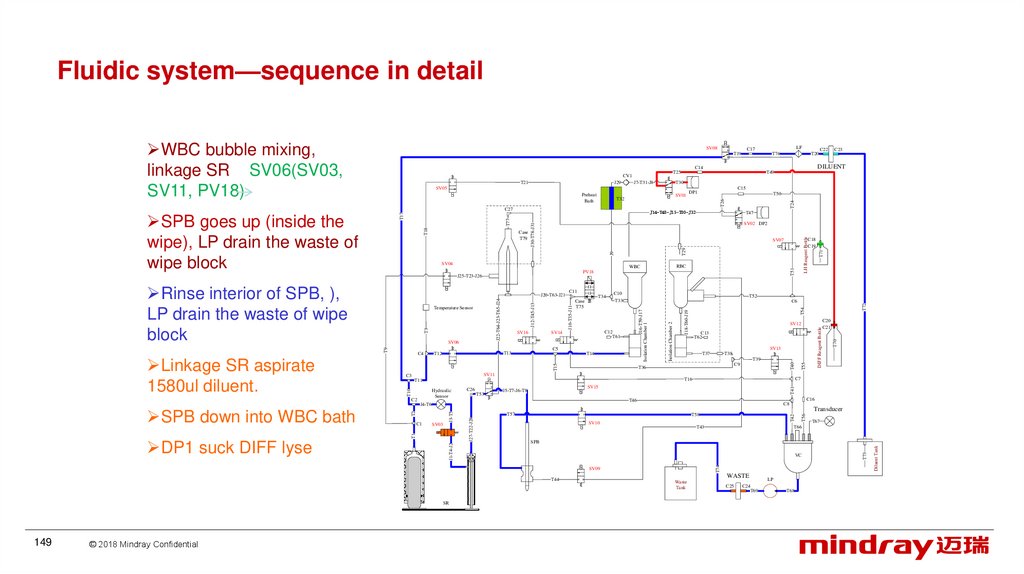
Rinse interior of SPB, ),
LP drain the waste of wipe
block
DP1 suck DIFF lyse
T20
C14
J25-T23-J26
SPB down into WBC bath
T76
T25
CV1
SPB goes up (inside the
wipe), LP drain the waste of
wipe block
Linkage SR aspirate
1580ul diluent.
LF
C17
T19
T70
WBC bubble mixing,
linkage SR SV06(SV03,
SV11, PV18)
150.
Fluidic system—sequence in detailEmpty RBC bath
SV08
LF
C17
T19
T76
T20
Preheat
Bath
SV01
T29
J9
SV10
© 2018 Mindray Confidential
T56
T72
T70
Transducer
T67
T66
T43
WASTE
Waste
Tank
C25
LP
C24
T69
T68
T73
VC
Diluent Tank
SPB
SV09
150
DIFF Reagent Bottle
C8
T58
T44
SR
T54
T41
C16
T46
T57
J27-T22-J28
J3-T5
SV03
C20
C21
C7
T16
SV15
J5-T7-J6-T8
T74
T10
T2
C1
T39
C9
T36
J4-T6
J1-T4-J2
Bubble mix WBC via
SV06.
T53
SV13
T38
T37
T55
T15
T14
SV12
C13
T62
T40
C5
SV11
C2
T51
C6
T11
C26
C18
C19
T52
T33
J18-T60-J19
J10-T35-J11
C10
C12
T61
SV14
T13
T12
T34
Case
T75
Isolation Chamber 1
SV16
C11
J16-T59-J17
Isolation Chamber 1
SV06
J12-T45-J13
J22-T64-J23-T65-J24
T3
Temperature Sensor
Hydraulic
Sensor
RBC
WBC
PV18
J20-T63-J21
LH Reagent Bottle
SV07
T71
J30-T78-J31
T18
T77
T17
Case
T79
T47
SV02 DP2
J25-T23-J26
C3
T50
J14-T48-J15-T80-J32
SV04
C4
C15
DP1
T26
T32
C27
T1
DP1 add DIFF lyse to
WBC bath
T30
J7-T31-J8
T24
J29
SV05
T9
SPB goes up (inside the
wipe),rinse exterior of
SPB LP drain the waste of
wipe block, then turn to
RBC bath.
T21
T49
T42
Small SPB aspirate 12ul
diluted sample from WBC
bath, large SPB for 480
diluent (SV03 off)
C23
DILUENT
C14
T25
CV1
C22
151.
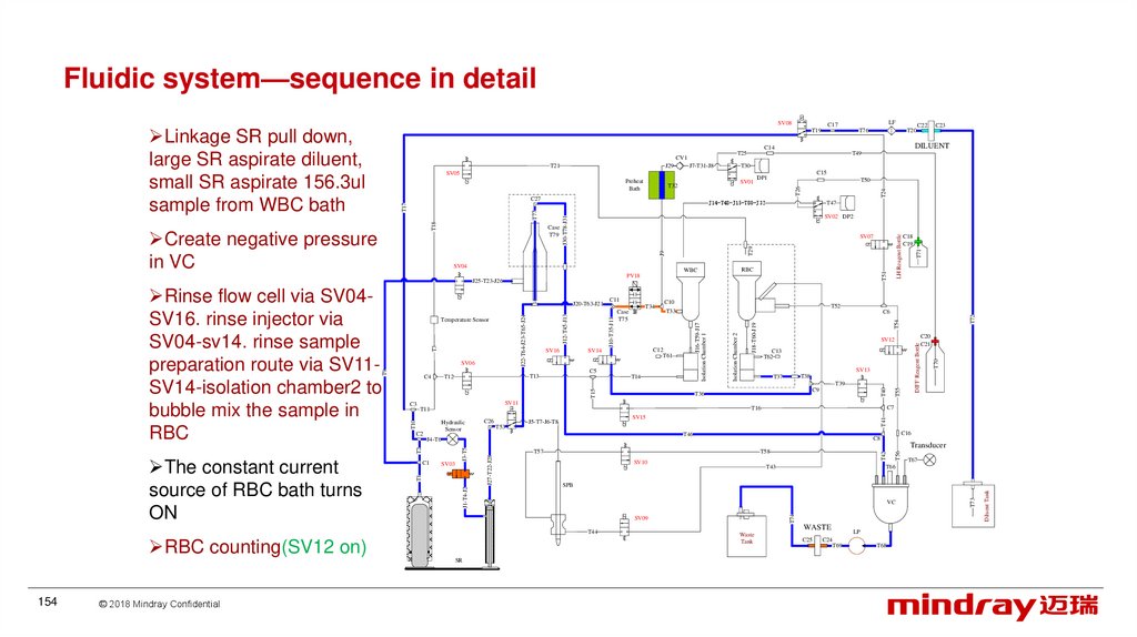
Fluidic system—sequence in detailSV08
LF
C17
T19
T76
T20
J29
T49
T30
J7-T31-J8
SV05
Preheat
Bath
SV01
© 2018 Mindray Confidential
T42
T70
DIFF Reagent Bottle
VC
WASTE
Waste
Tank
C25
LP
C24
T69
T68
T73
SPB
T44
151
T67
T66
T43
SV09
SR
T54
T41
Transducer
T58
SV10
Diluent Tank
J1-T4-J2
C16
C8
T57
J27-T22-J28
J3-T5
T2
SV03
C20
C21
C7
T46
J4-T6
C1
J18-T60-J19
T16
SV15
J5-T7-J6-T8
T56
T53
C9
T74
C2
C26
T39
T36
T11
Hydraulic
Sensor
SV13
T38
T37
T55
T15
T14
SV12
C13
T62
T40
C5
T72
C6
SV11
T10
C3
T51
T52
T33
Isolation Chamber 2
J10-T35-J11
C10
C12
T61
SV14
T13
T12
T34
Case
T75
J16-T59-J17
Isolation Chamber 1
SV16
C11
C18
C19
T71
J9
SV06
T9
J12-T45-J13
J22-T64-J23-T65-J24
T3
Temperature Sensor
C4
RBC
WBC
PV18
J20-T63-J21
T1
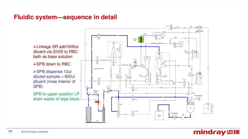
SPB to upper position LP
drain waste of wipe block
T29
SV07
SV04
SPB down to RBC
LH Reagent Bottle
J30-T78-J31
T18
Case
T79
T47
SV02 DP2
J25-T23-J26
SPB dispense 12ul
diluted sample + 800ul
diluent (rinse interior of
SPB)
T50
J14-T48-J15-T80-J32
T77
T17
C27
Linkage SR add1600ul
diluent via SV05 to RBC
bath as base solution
C15
DP1
T26
T32
T24
T21
C23
DILUENT
C14
T25
CV1
C22
152.
Fluidic system—sequence in detailSV08
LF
C17
T19
T76
T20
J29
T49
T30
J7-T31-J8
SV05
Preheat
Bath
T16
T72
T70
DIFF Reagent Bottle
C20
C21
C7
T41
SV15
J5-T7-J6-T8
T71
LH Reagent Bottle
T51
T54
C9
T36
T55
T40
T39
C16
C8
Transducer
T57
T42
T58
SV10
T67
T66
T43
WASTE
Waste
Tank
C25
LP
C24
T69
T68
T73
VC
SV09
Diluent Tank
SPB
T74
J1-T4-J2
SV13
T38
T37
T46
J27-T22-J28
J3-T5
T2
SV03
T1
C1
SV12
C13
T62
T56
T53
Isolation Chamber 2
J16-T59-J17
Isolation Chamber 1
T15
T14
T11
SR
© 2018 Mindray Confidential
C6
SV11
C26
C18
C19
T52
T33
C5
T44
152
C10
C12
T61
SV14
T13
T12
T34
Case
T75
J4-T6
Aspirate 200ul via C11T35 –SV14-ISC1, adjust
sample position
T26
J9
SV16
C11
J10-T35-J11
J12-T45-J13
J22-T64-J23-T65-J24
T3
T9
SV06
C2
RBC
WBC
PV18
Temperature Sensor
T10
DP2 suck LH lyse
T29
SV07
J20-T63-J21
Hydraulic
Sensor
T47
J30-T78-J31
T18
Case
T79
J25-T23-J26
C3
T50
SV02 DP2
SV04
C4
C15
DP1
J14-T48-J15-T80-J32
T77
T17
C27
SPB to the up position of
sampling
Linkage SR aspirate
380ul DIFF sample into
sample preparation
pipe(T65-T63),
T32
J18-T60-J19
Linkage SR aspirate
diluent from diluent tank
SV01
T24
T21
C23
DILUENT
C14
T25
CV1
C22
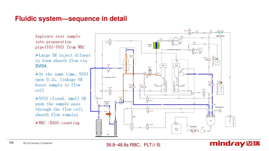
153.
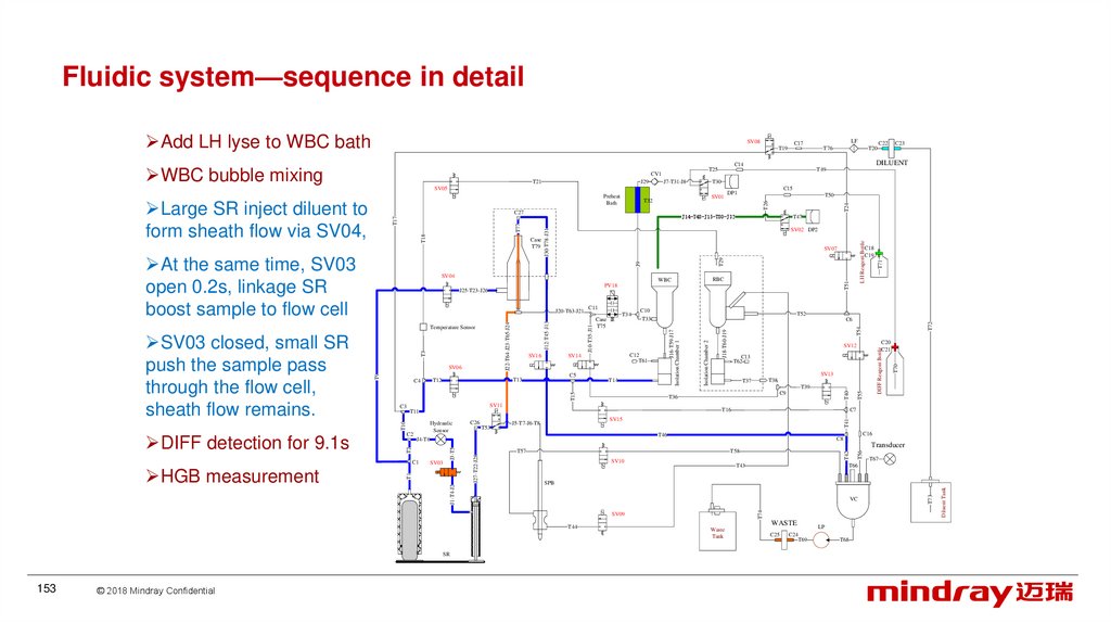
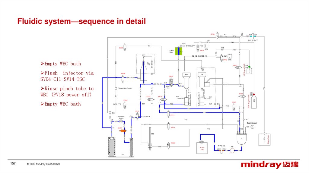
Fluidic system—sequence in detailAdd LH lyse to WBC bath
SV08
T49
SV01
© 2018 Mindray Confidential
T42
SV10
T56
T70
DIFF Reagent Bottle
Transducer
T67
T66
T43
VC
WASTE
Waste
Tank
C25
LP
C24
T69
T68
T73
SPB
T44
153
T54
T41
C8
T58
Diluent Tank
J1-T4-J2
C16
T46
SV09
SR
C7
T16
SV15
J5-T7-J6-T8
T57
J27-T22-J28
J3-T5
T2
T1
C9
T36
J4-T6
SV03
T39
T74
T10
T53
SV13
T38
T37
T55
T15
T14
C20
C21
SV12
C13
T62
T40
C5
J18-T60-J19
C12
T61
T72
C6
T11
C26
T71
T52
T33
SV11
C1
T51
C10
Isolation Chamber 2
J10-T35-J11
T34
Case
T75
SV14
T13
T12
C11
J16-T59-J17
Isolation Chamber 1
SV16
LH Reagent Bottle
T29
J9
SV06
T9
J12-T45-J13
J22-T64-J23-T65-J24
T3
Temperature Sensor
C2
RBC
WBC
PV18
J20-T63-J21
Hydraulic
Sensor
C18
C19
SV07
J25-T23-J26
C3
T47
SV02 DP2
SV04
C4
T50
J30-T78-J31
T18
T77
T17
At the same time, SV03
open 0.2s, linkage SR
boost sample to flow cell
C15
DP1
T26
T32
J14-T48-J15-T80-J32
Case
T79
C23
T30
J7-T31-J8
C27
C22
T24
J29
Preheat
Bath
Large SR inject diluent to
form sheath flow via SV04,
HGB measurement
T20
DILUENT
T25
CV1
T21
SV05
DIFF detection for 9.1s
T76
C14
WBC bubble mixing
SV03 closed, small SR
push the sample pass
through the flow cell,
sheath flow remains.
LF
C17
T19
154.
Fluidic system—sequence in detailSV08
J29
Preheat
Bath
T26
T71
T72
T54
DIFF Reagent Bottle
T41
SV10
T42
T58
T56
Transducer
T57
T67
T66
T43
VC
WASTE
Waste
Tank
C25
LP
C24
T69
T68
T73
SPB
Diluent Tank
J1-T4-J2
C16
C8
SV09
SR
C20
C21
C7
T16
SV15
J5-T7-J6-T8
T46
J27-T22-J28
J3-T5
T2
T1
C9
T36
J4-T6
SV03
T39
T74
T10
T53
SV13
T38
T37
T55
T15
T14
SV12
C13
T62
T40
C5
J18-T60-J19
C12
T61
Isolation Chamber 2
C6
T11
C26
C18
C19
T52
T33
SV11
C1
T51
C10
J16-T59-J17
Isolation Chamber 1
T34
Case
T75
SV14
T13
T12
LH Reagent Bottle
T29
J9
SV16
C11
J10-T35-J11
J12-T45-J13
J22-T64-J23-T65-J24
T3
T9
SV06
C2
RBC
WBC
PV18
Temperature Sensor
Hydraulic
Sensor
T47
SV07
J20-T63-J21
C3
T50
SV02 DP2
SV04
C4
C15
DP1
J30-T78-J31
T18
T77
T17
Case
T79
RBC counting(SV12 on)
© 2018 Mindray Confidential
SV01
T32
J14-T48-J15-T80-J32
T44
154
DILUENT
T30
J7-T31-J8
C27
C23
T24
T21
C22
T49
SV05
J25-T23-J26
The constant current
source of RBC bath turns
ON
T20
C14
T25
CV1
Create negative pressure
in VC
Rinse flow cell via SV04SV16. rinse injector via
SV04-sv14. rinse sample
preparation route via SV11SV14-isolation chamber2 to
bubble mix the sample in
RBC
T76
T70
Linkage SR pull down,
large SR aspirate diluent,
small SR aspirate 156.3ul
sample from WBC bath
LF
C17
T19
155.
Fluidic system—sequence in detailSV08
LF
C17
T19
T54
J18-T60-J19
DIFF Reagent Bottle
T41
C16
T46
C8
T42
T58
SV10
T56
Transducer
T57
T67
T66
T43
VC
SV09
SR
39.8~48.8s RBC、PLT计数
WASTE
Waste
Tank
C25
LP
C24
T69
T68
T73
SPB
Diluent Tank
J27-T22-J28
J3-T5
J1-T4-J2
C7
T16
SV15
J5-T7-J6-T8
J4-T6
T2
C9
T74
T10
T53
T39
T36
T11
C26
SV13
T38
T37
T55
T15
T14
C20
C21
SV12
C13
T62
T40
C5
T72
C6
C12
T61
SV14
T71
T52
T33
SV11
SV03
T51
C10
Isolation Chamber 2
T34
Case
T75
J16-T59-J17
Isolation Chamber 1
C11
J10-T35-J11
J12-T45-J13
J22-T64-J23-T65-J24
T3
SV16
T13
T12
LH Reagent Bottle
J9
T29
T18
J30-T78-J31
T77
T17
T9
SV06
C1
RBC
WBC
Temperature Sensor
C2
C18
C19
PV18
J20-T63-J21
Hydraulic
Sensor
T47
SV07
J25-T23-J26
C3
T50
SV02 DP2
SV04
C4
C15
DP1
T26
T32
T44
© 2018 Mindray Confidential
SV01
J14-T48-J15-T80-J32
Case
T79
WBC /BASO counting
155
T30
J7-T31-J8
C27
T1
SV03 closed, small SR
push the sample pass
through the flow cell,
sheath flow remains
J29
T49
SV05
Preheat
Bath
C23
T24
T21
C22
DILUENT
C14
T25
CV1
Large SR inject diluent
to form sheath flow via
SV04,
At the same time, SV03
open 0.2s, linkage SR
boost sample to flow
cell
T20
T70
Aspirate rest sample
into preparation
pipe(T63-T65) from WBC
T76
156.
Fluidic system—sequence in detailSV08
LF
C17
T19
T76
T20
J29
T49
T30
J7-T31-J8
SV05
Preheat
Bath
SV01
T29
J9
T52
T33
T72
T54
C13
T62
SV13
T38
T37
T42
SV10
T67
T66
T43
VC
SV09
WASTE
Waste
Tank
C25
LP
C24
T69
T68
T73
SPB
T44
SR
T55
T41
Transducer
T58
Diluent Tank
J1-T4-J2
C8
T57
J27-T22-J28
J3-T5
T2
SV03
T1
C1
C16
T46
T56
T53
SV15
J5-T7-J6-T8
T74
Hydraulic
Sensor
C7
T16
T11
C26
C9
T36
SV11
T40
T15
C3
C20
C21
T70
J18-T60-J19
SV12
DIFF Reagent Bottle
T14
Isolation Chamber 2
C6
C5
J4-T6
© 2018 Mindray Confidential
C18
C19
T39
C2
156
T51
C10
C12
T61
SV14
T13
T12
T34
Case
T75
J16-T59-J17
Isolation Chamber 1
SV06
SV16
C11
J10-T35-J11
J12-T45-J13
J22-T64-J23-T65-J24
T3
Temperature Sensor
T10
Linkage SR aspirate
diluent.
J20-T63-J21
C4
RBC
WBC
PV18
J25-T23-J26
LH Reagent Bottle
SV07
T71
J30-T78-J31
T18
Case
T79
T47
SV02 DP2
SV04
T9
Rinse sample
preparation pipe via
(PV18 power on) SV03SV11-C11-SV14、rinse
flow cell via sv04-sv16
T50
J14-T48-J15-T80-J32
T77
T17
C27
Empty RBC bath
C15
DP1
T26
T32
T24
T21
C23
DILUENT
C14
T25
CV1
C22
157.
Fluidic system—sequence in detailSV08
LF
C17
T19
T76
T20
J29
T49
T30
J7-T31-J8
SV05
Preheat
Bath
SV01
© 2018 Mindray Confidential
T71
T72
T70
T41
Transducer
T57
T42
T58
SV10
T67
T66
T43
VC
WASTE
Waste
Tank
C25
LP
C24
T69
T68
T73
SPB
T44
157
T54
J18-T60-J19
C16
C8
SV09
SR
C7
T16
SV15
J5-T7-J6-T8
C20
C21
Diluent Tank
J1-T4-J2
C9
T46
J27-T22-J28
J3-T5
T2
T1
SV03
T39
T36
J4-T6
C1
SV13
T38
T37
T56
T53
C13
T62
T74
C2
C26
DIFF Reagent Bottle
T15
T14
SV12
T40
C5
Isolation Chamber 2
C6
T11
Hydraulic
Sensor
LH Reagent Bottle
T52
T33
SV11
T10
C3
T51
C10
C12
T61
SV14
T13
T12
T34
Case
T75
J16-T59-J17
Isolation Chamber 1
T9
SV06
SV16
C11
J10-T35-J11
T3
Temperature Sensor
C4
J12-T45-J13
J22-T64-J23-T65-J24
Rinse pinch tube to
WBC (PV18 power off)
RBC
WBC
PV18
J25-T23-J26
C18
C19
T55
SV04
J20-T63-J21
Empty WBC bath
T29
SV07
J9
Case
T79
T47
SV02 DP2
J30-T78-J31
T18
Flush injector via
SV04-C11-SV14-ISC
T50
J14-T48-J15-T80-J32
T77
T17
C27
Empty WBC bath
C15
DP1
T26
T32
T24
T21
C23
DILUENT
C14
T25
CV1
C22
158.
Fluidic system—sequence in detailSV08
LF
C17
T19
T76
T20
J29
Preheat
Bath
T26
T71
LH Reagent Bottle
T51
T72
T54
T70
DIFF Reagent Bottle
T40
Isolation Chamber 2
J18-T60-J19
C16
C8
Transducer
T57
T58
SV10
T67
T66
T43
VC
SV09
WASTE
Waste
Tank
C25
LP
C24
T69
T68
T73
SPB
T44
SR
C7
T16
SV15
J5-T7-J6-T8
Diluent Tank
J1-T4-J2
C9
T36
T46
J27-T22-J28
J3-T5
T2
SV03
T1
C1
T39
C20
C21
T41
T53
SV13
T38
T37
T74
T10
C2
C26
SV12
C13
T62
T55
T15
T14
T11
Ready for next test.
© 2018 Mindray Confidential
C6
SV11
Hydraulic
Sensor
C18
C19
T52
T33
C5
J4-T6
Release vacuum pressure
(SV10 on, LP off)
C10
C12
T61
SV14
T13
T12
T34
Case
T75
J16-T59-J17
Isolation Chamber 1
SV16
C11
J10-T35-J11
T3
SV06
T9
J12-T45-J13
J22-T64-J23-T65-J24
Temperature Sensor
C3
RBC
WBC
PV18
T56
T18
J9
T29
SV07
J20-T63-J21
C4
T47
SV02 DP2
J25-T23-J26
SPB to ready position
T50
J30-T78-J31
T77
T17
Case
T79
Turn on the LP rinse
wipe block
C15
DP1
J14-T48-J15-T80-J32
SV04
158
SV01
T32
C27
Add 2018ul diluent to
WBC bath
Small SR aspirate 4ul
air to create an
isolation bubble
T30
J7-T31-J8
SV05
T24
T21
T49
T42
Add 2560ul diluent to
RBC bath
C23
DILUENT
C14
T25
CV1
C22
159.
Fluidic system—sequence in detailMeasurement sequence in PD-CBC+DIFF mode
Measurement sequence in PD-CBC+DIFF mode is basically the same
with the sequence in WB-CBC+DIFF mode, except that:
Blood sample has been prediluted outside the analyzer,
200μL of prediluted blood is aspirated in the PD mode
Measurement sequence in CBC mode
Compared with the sequence in CBC+DIFF mode, the measurement
sequence in CBC mode is basically the same except that:
Sample volume: 15μL in the WB-CBC+DIFF mode, 11.7μL in the WBCBC mode.(but for PD mode, CBC+DIFF and CBC mode are the same )
There is no actions related to DIFF measurement, including addition of DIFF
reagent, preparation of DIFF samples, DIFF measurement, and cleaning
process of the tubes and the flow cell after the DIFF measurement.
159
© 2018 Mindray Confidential
160.
Fluidic system—sequence for maintenanceMaintenance with probe cleanser(shut down
SV08
LF
C17
T19
J29
T49
T30
J7-T31-J8
SV05
Preheat
Bath
SV01
T52
T33
T72
T54
J18-T60-J19
DIFF Reagent Bottle
T41
C8
T42
T58
SV10
T56
Transducer
T57
T67
T66
T43
SV09
WASTE
Waste
Tank
C25
LP
C24
T69
T68
T73
VC
Diluent Tank
SPB
T2
T1
J1-T4-J2
J27-T22-J28
J3-T5
C16
T46
T74
T10
T53
T44
SR
C7
T16
J5-T7-J6-T8
SV03
C9
SV15
C26
J4-T6
C1
T39
T36
T11
C2
SV13
T38
T37
T55
T15
T14
C20
C21
SV12
C13
T62
T40
C5
Isolation Chamber 1
C6
SV11
Hydraulic
Sensor
T51
C10
C12
T61
SV14
T13
T12
T34
Case
T75
J16-T59-J17
Isolation Chamber 1
SV16
C11
J10-T35-J11
T3
T9
SV06
J12-T45-J13
J22-T64-J23-T65-J24
J20-T63-J21
C3
RBC
WBC
C18
C19
T71
J9
T29
SV07
PV18
Temperature Sensor
LH Reagent Bottle
J30-T78-J31
T18
T77
T17
Case
T79
T47
SV02 DP2
J25-T23-J26
C4
T50
J14-T48-J15-T80-J32
SV04
enhanced probe cleanser
maintenance sequence
will be called every 300
times of sample
measurement.
The soaking time of
enhanced maintenance is
6.67S
In the Maintenance
screen, the probe
cleanser maintenance is
defaulted as enhanced
probe cleanser
© 2018 Mindraymaintenance.
Confidential
C15
DP1
T26
T32
C27
C23
T24
T21
C22
DILUENT
C14
T25
CV1
the blue lines are the
locations passed by the
probe cleanser
160
T20
T70
The orange lines are the
locations soaked by the
probe cleanser,
T76
161.
Fluidic system—sequence in detailStarting up rinse
The fluidic actions on startup can be divided into three procedures:
1. Initialization of fluidics components: initialization of sampling assembly and
syringe assembly; 1 metering pump action (without consumption of reagents);
creating vacuum and releasing vacuum.
2. Cleanup: including cleaning of all the tubes and components on the analyzer;
removing bubbles from the flow cell; discarding 1 ml of DIFF reagent and 0.2 ml
of LH reagent.
3. Background: with WB-CBC+DIFF measurement sequence
If the background fails, perform the cleanup again and measure the
background.
For startup after an abnormal shutdown, perform the cleanup twice.。
Initialization of fluidics components, cleaning up of the interior and exterior
surface of the sample probe while starting up after updating
161
© 2018 Mindray Confidential
162.
Fluidic system—standbyThe instrument will enter standby status after idling for 15 to 30 minutes
(defaulted as 15 minutes). After entering standby status, operations without fluidic
actions can be performed from the screen.
Exit standby status 1: Standby for less than 1 hour.
Clean the exterior of the sample probe and the WBC bath and rebuild the isolation
bubble without consumption of lyse.
Exit standby status 2: Standby for more than 1 hour and less than 5 hour.
Clean the interior and exterior of the sample probe, the WBC bath, the RBC bath,
the sample supply tube and the flow cell, and rebuild the isolation bubble without
consumption of lyse.
Exit standby status 3: Standby for not less than 5 hour.
The same as cleanup on startup, including cleaning of all the tubes and
components on the analyzer; removing bubbles from the flow cell; discarding 3 ml of
DIFF reagent to eliminate the effects of bubbles in the preheat bath tube; discarding 0.2
ml of LH reagent to eliminate the effects of crystal and bubbles.
162
© 2018 Mindray Confidential
163.
163© 2018 Mindray Confidential
164.
ContentClinics
Overview
Principle
Installation
Software
Hardware
Optical system
Liquid system
Mechanical structure
164
© 2018 Mindray Confidential
165.
Mechanical system—overall layout① 2-way valve
② 3-way valve
③ Syringe assemly
④ 1ml metering pump
⑤ microswitch
⑥ [aspirate] key
⑦
200ulmetering pump
⑧ Sampling assembly
⑨ Fluidic pressure
sensor
Front view of the main unit (cover opened)
165
© 2018 Mindray Confidential
166.
Mechanical system—overall layout① Analog drive board
② Main control board
③ Fan assembly
Back view of the main unit (internal structure)
166
© 2018 Mindray Confidential
167.
Mechanical system—overall layout①
②
③
④
⑤
⑥
⑦
Left view of the main unit (left
door removed)
167
© 2018 Mindray Confidential
Optical system
Front cover
Reagent baffle
LH lyse
DIFF lyse
Net 、USB interface
Power supply
assembly
168.
Mechanical system—overall layout①
②
③
④
⑤
⑥
⑦
⑧
⑨
⑩
Fluid inlet/outlet
Waste pump
Vacuum chamber
valve
LVM valve
Diluent Temp. sensor
Sampling assembly
Front cover
RBC bath
WBC bath
Right view of the main unit (right door removed)
168
© 2018 Mindray Confidential
169.
Mechanical system—overall layout①
②
③
④
⑤
⑥
⑦
⑧
RBC bath subassembly
169
© 2018 Mindray Confidential
Bath cap
Pan head screw M3X6
Bath holder
Bath adjust holder
RBC bath
Aperture (D50um)
Front bath washer
RBC back bath
170.
Mechanical system—overall layout①
②
③
④
⑤
⑥
WBC bath assembly
170
© 2018 Mindray Confidential
Bath cap
Pan head screw M3X6
Bath holder
Bath adjust holder
WBC bath
HGB assembly
171.
Mechanical system—disassemblingRBC bath maintenance assembly
171
© 2018 Mindray Confidential
172.
Mechanical system—disassemblingpipes are fixed to the holder
with cable tie
Winding pipe and
adapter should
be tied up with
cable tie
172
© 2018 Mindray Confidential
Replace with specific pipe and
surround with winding pipe as
illustration in the figure
173.
Mechanical system—disassemblingDisassembly rear plate of power
supply assembly
173
© 2018 Mindray Confidential
174.
Mechanical system—adjustment of bath position174
© 2018 Mindray Confidential
175.
Mechanical system—adjustment of bath positionOperation
Procedure
1.1
1.2
1.3
1.4
Quality Control
Operation content
QC Point
QC Standard
Fine adjust
the relative
position of
the bath
The sample
probe is
basically in the
center of the
bath
Check if
the bath
position is
successfully
adjusted
The sample
probe can not
contact with the
bath。
Click on “Service → Sample Probe Debug”. Enter the
Debug screen as shown in Figure 1.1.
First, click on the “Initial position” so that the sample
probe is above the RBC bath, as shown in Figure 1.2.
Click on the “WBC bath”(or “RBC bath”) button shown in
Figure 1.2. Click the “Middle position” button. Check if the
sample probe is basically in the center of the bath. If there
is any deviation, loosen the four screws shown in Figure
1.3 and slightly adjust the bath in left/right and front/back
directions so that the sample probe is in the center of the
bath. Then tighten one screw in each direction
Click on the “Initial position” button, then click “WBC
bath”(“RBC bath”) →“Down position” button. Check there
is no interference with the bath as the sample probe
enters the bath. If the interference occurs, readjust the
bath position in accordance with step 1-3 and repeat this
step to check. Finally, tighten the 4 screws.
Note:
In Figure 1.1, all the buttons except the “Initialization” button will be grey before clicking on Initialization, the
three buttons in the “Sample probe horizontal position” column will be illuminated and available for use Only
after clicking on Initialization. The “Middle position” and “Down position” buttons will not be available until
clicking on the “WBC bath” or “RBC bath” button.
175
© 2018 Mindray Confidential
176.
Preheating temperature calibration and verificationFill in the sum of the machine
measurement value and the FRU
value
Machine
measurement value
Operation
Procedure
2.1
2.2
176
© 2018 Mindray Confidential
Operation Content
Click the Start Menu bar, then click
“Service→
Temp.& Press.
Calibration” to enter the
“Temperature calibration” screen.
Click on the “Preheat bath
temperature calibration” button to
enter the software calibration menu
Record the machine measurement
value, and enter the sum of the
machine measurement value and
the value on the service FRU as the
meter measurement value
Quality Control
QC Point
Measure the
preheat bath
temperature
calibration factor
QC Standard
177.
Mechanical system—matters need attentionAll parts of the analyzer are potential infectious, safety protection measures
should be taken during operation and maintenance
Reagents may irritate eyes, skin and mucous membrane. Operator who
contact such items as reagent in the laboratory, should comply with the
laboratory safety operating rules, and wear personal protective outfit (such as
laboratory protective clothing, gloves, etc.)
Once the skin is in contact with Reagent, wash immediately with plenty of
water, if necessary, please go to see a doctor; Once the reagent is splashed
into your eyes, rinse immediately with plenty of water, and treated by doctors
when removing some component with electrostatic sensitive sign, electrostatic
ring or static gloves and other protective equipment need to be equipped to
avoid damage to the parts
Choose the correct specifications and models of tube and screw
keep the original tube length. Any prolongation and shortening are strictly
forbidden.
Pay attention that the tube and cable could not bend or squeeze,
when reinstall, to prevent block or short circuit
177
© 2018 Mindray Confidential
178.
Version Information178
Version
Author
Date
Description
1.0
Fisher Zhang
29/10/2013
Initial Release
2.0
Mark Wu
23/05/2018
Update
© 2018 Mindray Confidential
179.
Check Information179
Version
Reviewer
Date
Comments
1.0
Luke Liao
29/10/2014
Initial Release
2.0
Luke Liao
23/05/2018
Update
© 2018 Mindray Confidential
180.
Thanks180
© 2018 Mindray Confidential