


 programming
Similar presentations:


Microcontroller Programming Lecture 5
1.
Microcontroller ProgrammingLecture 5
2.
CHAPTER 9: AVR TIMER PROGRAMMING IN C• SECTION 9.1: PROGRAMMING TIMERS 0, 1 AND 2
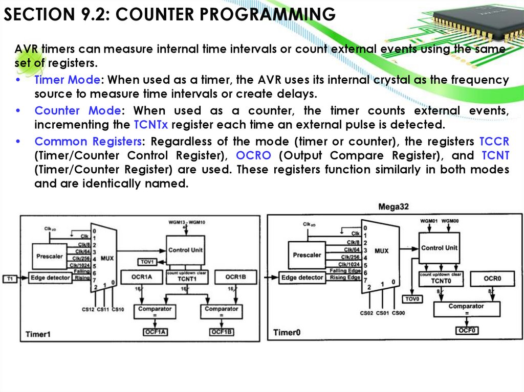
• SECTION 9.2: COUNTER PROGRAMMING
• SECTION 9.3: PROGRAMMING TIMERS IN C
3.
Counter - Digital ElectronicsThe diagram you provided shows an asynchronous (ripple) counter
constructed using JK flip-flops.
Frequency divider
Edge triggering
Number FF
Frequency
Clock
CLK/1
Q0
CLK/2
Q1
CLK/4
Q2
CLK/6
Q3
CLK/8
4.
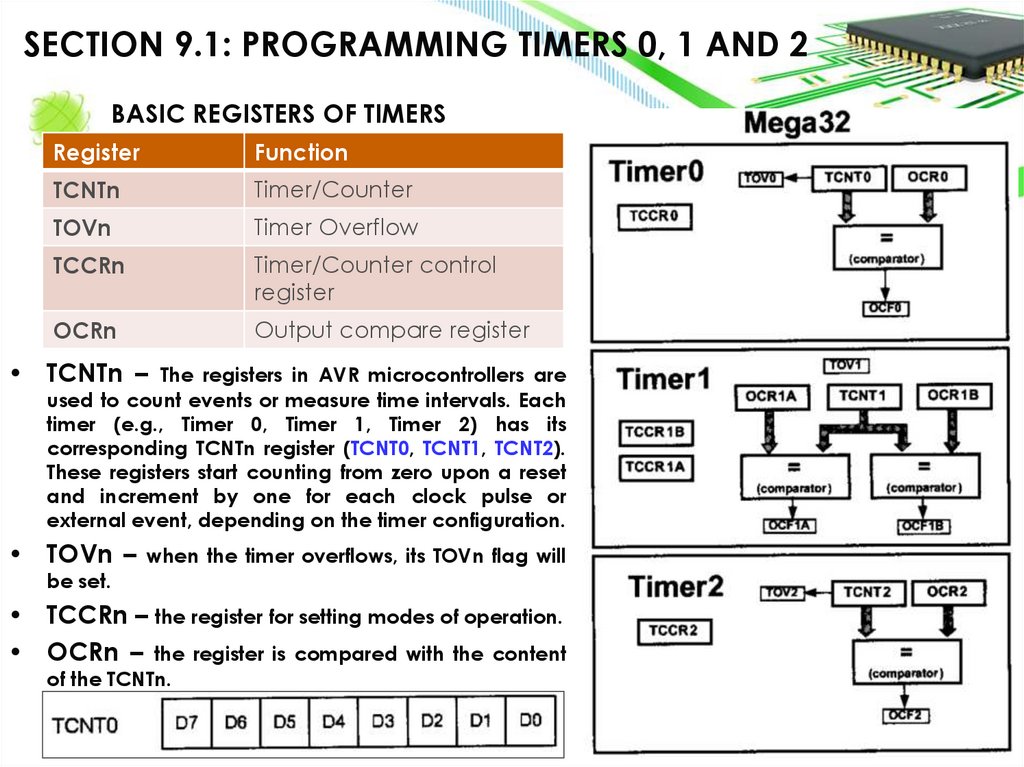
SECTION 9.1: PROGRAMMING TIMERS 0, 1 AND 2BASIC REGISTERS OF TIMERS
Register
Function
TCNTn
Timer/Counter
TOVn
Timer Overflow
TCCRn
Timer/Counter control
register
OCRn
Output compare register
• TCNTn – The registers in AVR microcontrollers are
used to count events or measure time intervals. Each
timer (e.g., Timer 0, Timer 1, Timer 2) has its
corresponding TCNTn register (TCNT0, TCNT1, TCNT2).
These registers start counting from zero upon a reset
and increment by one for each clock pulse or
external event, depending on the timer configuration.
• TOVn – when the timer overflows, its TOVn flag will
be set.
• TCCRn – the register for setting modes of operation.
• OCRn – the register is compared with the content
of the TCNTn.
5.
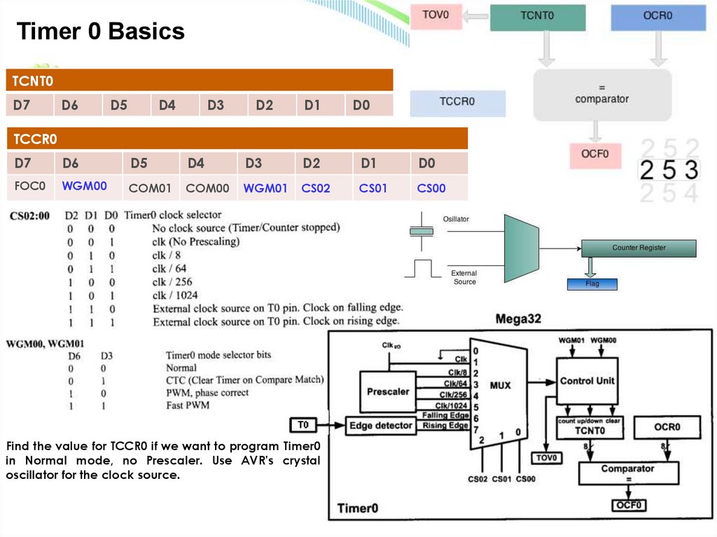
Timer 0 BasicsTCNT0
D7
D6
D5
D4
D3
D2
D1
D0
TCCR0
D7
D6
D5
D4
D3
D2
D1
D0
FOC0
WGM00
COM01
COM00
WGM01
CS02
CS01
CS00
Find the value for TCCR0 if we want to program Timer0
in Normal mode, no Prescaler. Use AVR’s crystal
oscillator for the clock source.
6.
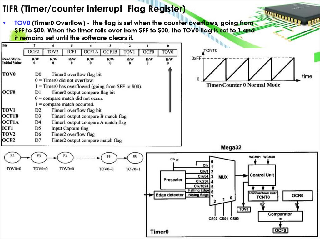
TIFR (Timer/counter interrupt Flag Register)TOV0 (Timer0 Overflow) - the flag is set when the counter overflows, going from
$FF to $00. When the timer rolls over from $FF to $00, the TOV0 flag is set to 1 and
it remains set until the software clears it.
7.
Config Timer0TCCR0
D7
D6
D5
D4
D3
D2
D1
D0
FOC0
WGM00
COM01
COM00
WGM01
CS02
CS01
CS00
D6
D5
D1
D0
TCNT0
D7
D4
D3
D2
8.
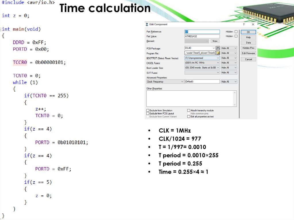
Time calculationCLK = 1MHz
CLK/1024 = 977
T = 1/997= 0.0010
T period = 0.0010×255
T period = 0.255
Time = 0.255×4 ≈ 1
9.
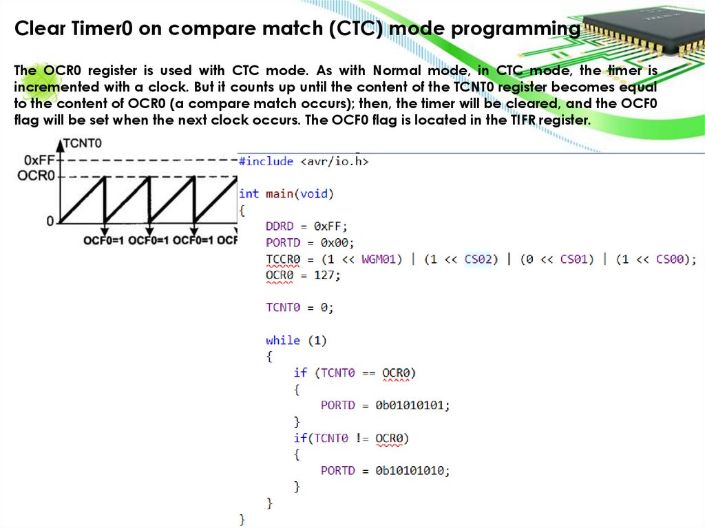
Clear Timer0 on compare match (CTC) mode programmingThe OCR0 register is used with CTC mode. As with Normal mode, in CTC mode, the timer is
incremented with a clock. But it counts up until the content of the TCNT0 register becomes equal
to the content of OCR0 (a compare match occurs); then, the timer will be cleared, and the OCF0
flag will be set when the next clock occurs. The OCF0 flag is located in the TIFR register.
10.
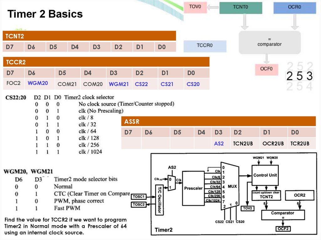
Timer 2 BasicsTCNT2
D7
D6
D5
D4
D3
D2
D1
D0
TCCR2
D7
D6
D5
D4
D3
D2
D1
D0
FOC2
WGM20
COM21
COM20
WGM21
CS22
CS21
CS20
ASSR
D7
Find the value for TCCR2 if we want to program
Timer2 in Normal mode with a Prescaler of 64
using an internal clock source.
D6
D5
D4
D3
D2
D1
D0
AS2
TCN2UB
OCR2UB
TCR2UB
11.
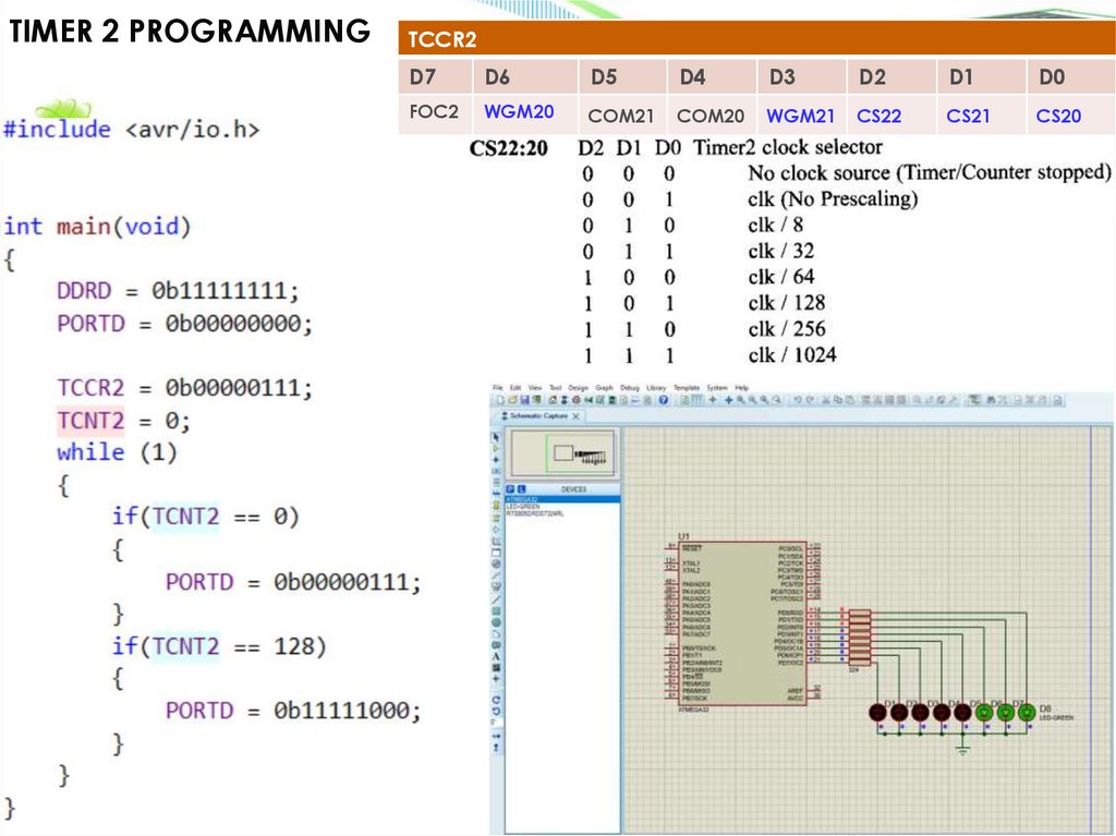
TIMER 2 PROGRAMMINGTCCR2
D7
D6
D5
D4
D3
D2
D1
D0
FOC2
WGM20
COM21
COM20
WGM21
CS22
CS21
CS20
12.
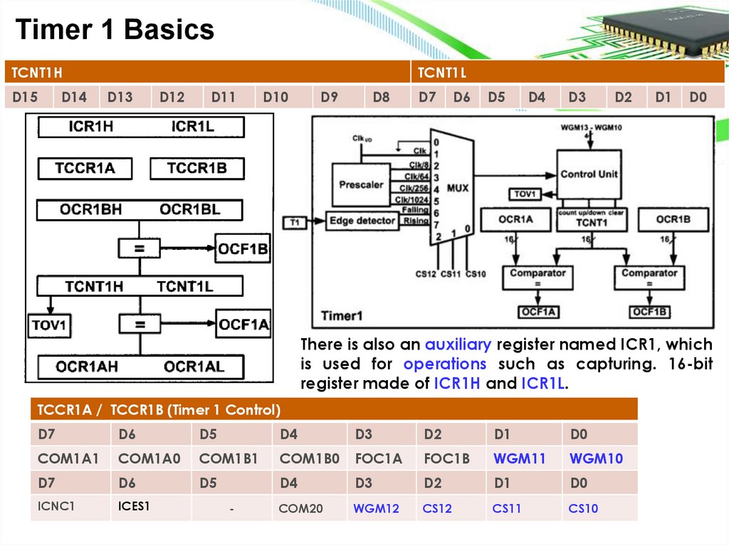
Timer 1 BasicsTCNT1H
D15
D14
TCNT1L
D13
D12
D11
D10
D9
D8
D7
D6
D5
D4
D3
D2
D1
D0
There is also an auxiliary register named ICR1, which
is used for operations such as capturing. 16-bit
register made of ICR1H and ICR1L.
TCCR1A / TCCR1B (Timer 1 Control)
D7
D6
D5
D4
D3
D2
D1
D0
COM1A1
COM1A0
COM1B1
COM1B0
FOC1A
FOC1B
WGM11
WGM10
D7
D6
D5
D4
D3
D2
D1
D0
ICNC1
ICES1
COM20
WGM12
CS12
CS11
CS10
-
13.
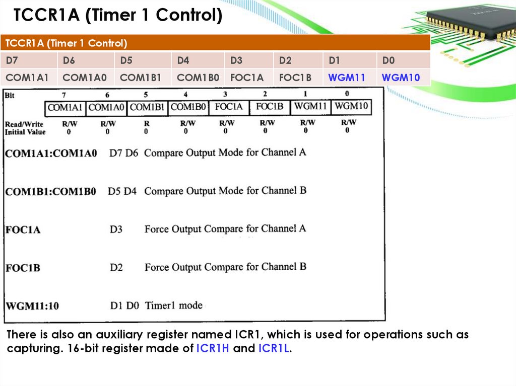
TCCR1A (Timer 1 Control)TCCR1A (Timer 1 Control)
D7
D6
D5
D4
D3
D2
D1
D0
COM1A1
COM1A0
COM1B1
COM1B0
FOC1A
FOC1B
WGM11
WGM10
There is also an auxiliary register named ICR1, which is used for operations such as
capturing. 16-bit register made of ICR1H and ICR1L.
14.
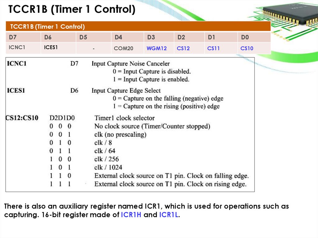
TCCR1B (Timer 1 Control)TCCR1B (Timer 1 Control)
D7
D6
ICNC1
ICES1
D5
-
D4
D3
D2
D1
D0
COM20
WGM12
CS12
CS11
CS10
There is also an auxiliary register named ICR1, which is used for operations such as
capturing. 16-bit register made of ICR1H and ICR1L.
15.
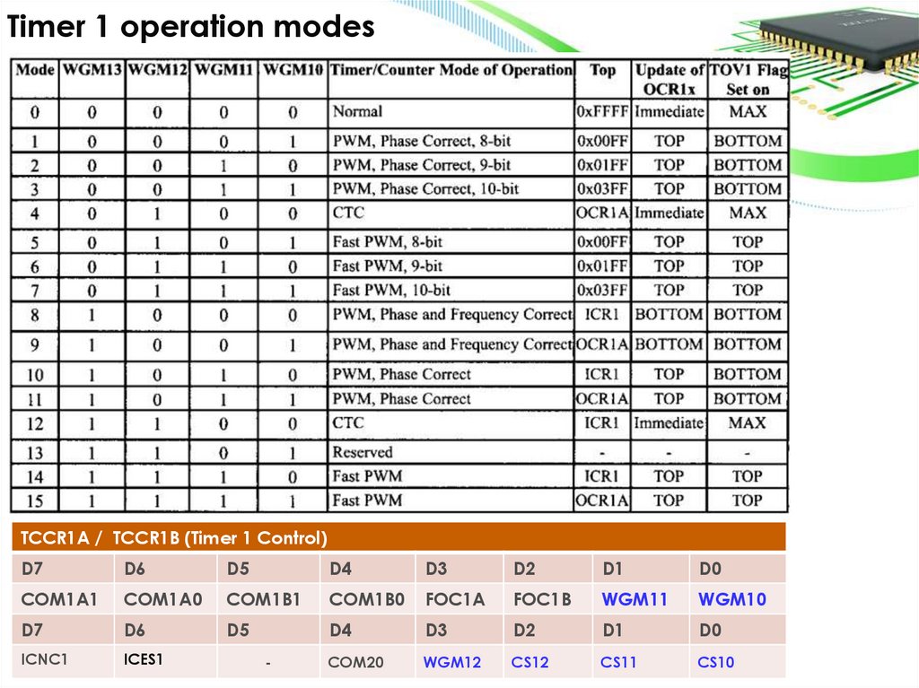
Timer 1 operation modesTCCR1A / TCCR1B (Timer 1 Control)
D7
D6
D5
D4
D3
D2
D1
D0
COM1A1
COM1A0
COM1B1
COM1B0
FOC1A
FOC1B
WGM11
WGM10
D7
D6
D5
D4
D3
D2
D1
D0
ICNC1
ICES1
COM20
WGM12
CS12
CS11
CS10
-
16.
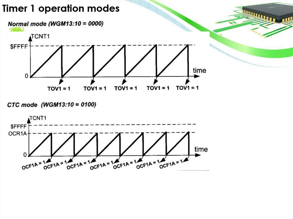
Timer 1 operation modes17.
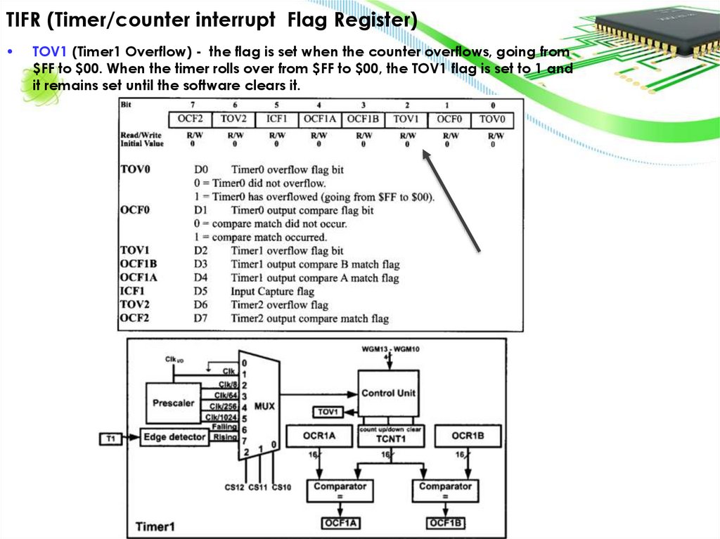
TIFR (Timer/counter interrupt Flag Register)TOV1 (Timer1 Overflow) - the flag is set when the counter overflows, going from
$FF to $00. When the timer rolls over from $FF to $00, the TOV1 flag is set to 1 and
it remains set until the software clears it.
18.
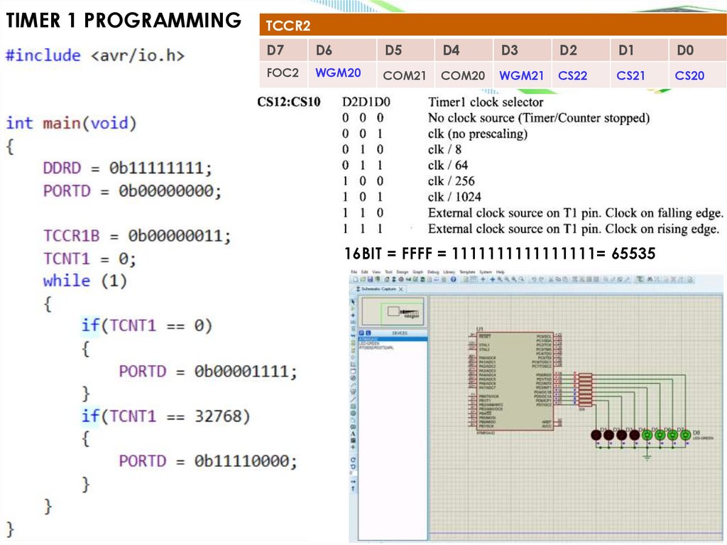
TIMER 1 PROGRAMMINGTCCR2
D7
D6
D5
D4
D3
D2
D1
D0
FOC2
WGM20
COM21
COM20
WGM21
CS22
CS21
CS20
16BIT = FFFF = 1111111111111111= 65535
19.
SECTION 9.2: COUNTER PROGRAMMINGAVR timers can measure internal time intervals or count external events using the same
set of registers.
• Timer Mode: When used as a timer, the AVR uses its internal crystal as the frequency
source to measure time intervals or create delays.
• Counter Mode: When used as a counter, the timer counts external events,
incrementing the TCNTx register each time an external pulse is detected.
• Common Registers: Regardless of the mode (timer or counter), the registers TCCR
(Timer/Counter Control Register), OCRO (Output Compare Register), and TCNT
(Timer/Counter Register) are used. These registers function similarly in both modes
and are identically named.
20.
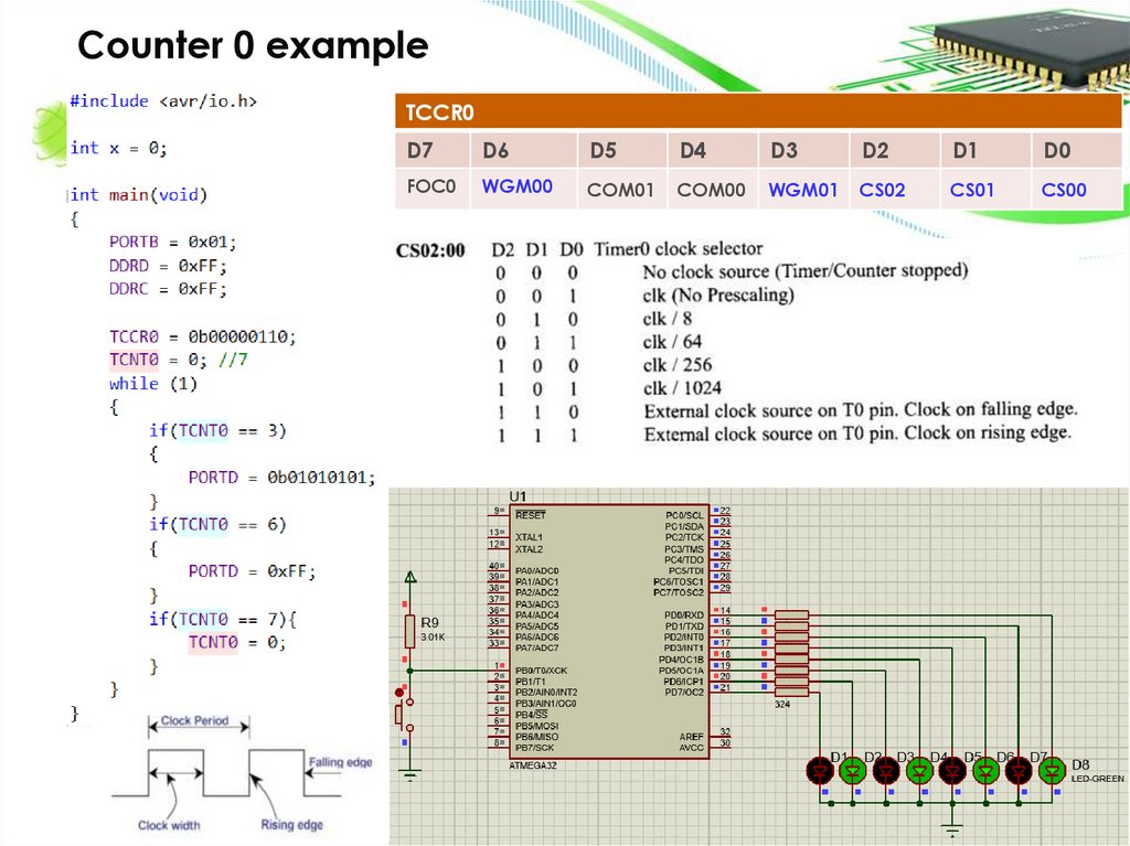
Counter 0 exampleTCCR0
D7
D6
D5
D4
D3
D2
D1
D0
FOC0
WGM00
COM01
COM00
WGM01
CS02
CS01
CS00
21.
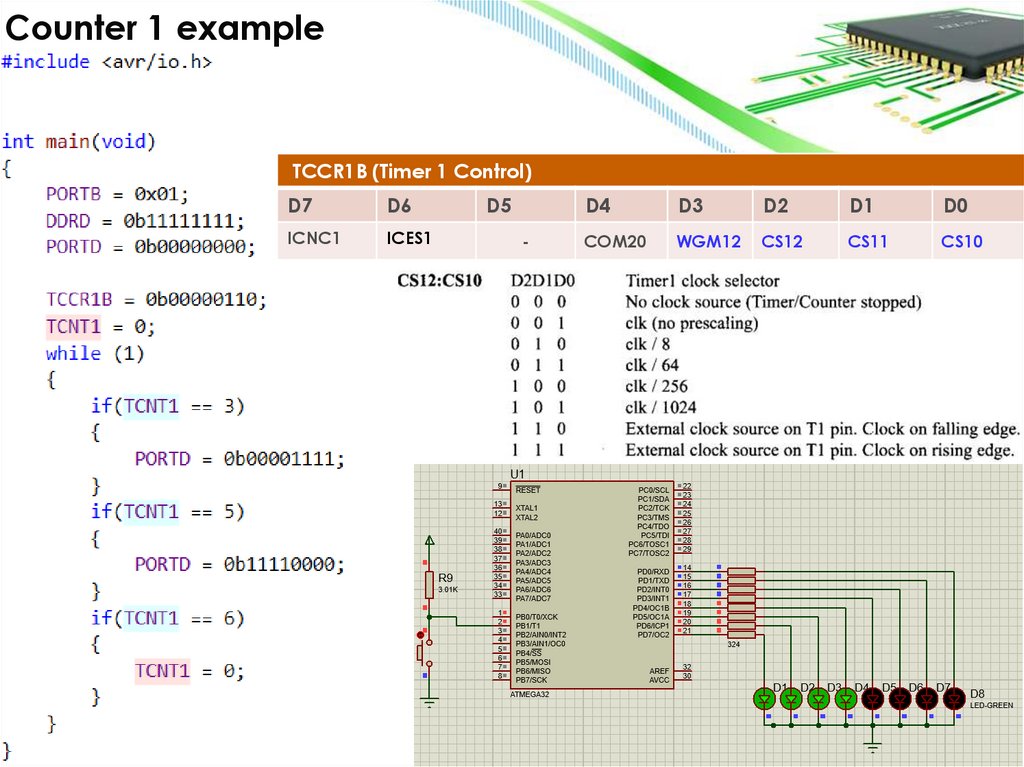
Counter 1 exampleTCCR1B (Timer 1 Control)
D7
D6
ICNC1
ICES1
D5
-
D4
D3
D2
D1
D0
COM20
WGM12
CS12
CS11
CS10
22.
Thanks for your attention!• Thanks for your attention!