


")
")


")


")

")


")


")

")
")


")
")


 informatics
Similar presentations:


")


TrueType Fundamentals
1. TrueType Fundamentals
By Amir Shiri2. Lecture content
This lecture introduces the basic conceptsneeded to create and instruct a TrueType
font. It begins with an overview of the steps
involved in taking a design from paper to
the creation of a bitmap that can be sent to
an output device and follows with a closer
look at each of the steps in the process.
3. What is a TrueType font ?
A digital font that contains much more thanjust the characters associated with a given
alphabet or script. A TrueType font file
includes many different kinds of information
used by the TrueType rasterizer and the
operating system software to ensure that
characters display on the computer screen or
print out exactly as the font designer
intended them to.
4. From design to font file
5. From Font File to Paper
This section describes the process that allowsglyphs from a TrueType font file to be
displayed on raster devices.
6. From Font File to Paper (Cont.)
First, the outline stored in the font file isscaled to the requested size. Once scaled, the
points that make up the outline are no longer
recorded in the FUnits used to describe the
original outline, but have become devicespecific pixel coordinates.
7. From Font File to Paper (Cont.)
Next, the instructions associated with thisglyph are carried out by the interpreter. The
result of carrying out the instructions is a
grid-fitted outline for the requested glyph.
This outline is then scan converted to
produce a bitmap that can be rendered on
the target device.
8.
FUnitsFUnits
FUnits
FUnits
pixel
coordinates
a (x,y)
c (x,y)
d (x,y)
Digitize outline with
FUnit coordinates
in TrueType font file
c (x,y)
d (x,y)
pt size 12
0> NPUS HB[]
1> S RP 0[] 48
2> S ROUND[] 71
3> MDRP[00100] 49
4> RTG[]
5> MIRP[10110] 22 75
6> MIRP[11110] 37 37
7> ALIGNRP [] 24
8> S RP 0[] 49
9> MDRP [11110]
10> DELTAP1[] 1
a (x,y)
c (x,y)
c (x,y)
d (x,y)
d (x,y)
e (x,y)
Interpreter executes
instructions associated
with glyph "B" and gridfits
Scaled outline
with pixel
coordinates
pt size 12
Outline "sized"
to new grid
a (x,y)
a (x,y)
e (x,y)
e (x,y)
Scaler converts FUnits
to pixel coordinates and
scales outline to size
requested by application
e (x,y)
Grid-fitted outline
a (x,y)
c (x,y)
d (x,y)
e (x,y)
Grid-fitted outline
Scan converter decides
which pixels to turn on
Bitmap is rendered on
raster device
9. Digitizing a design
This section describes the coordinate systemused to establish the locations of the points
that define a glyph outline. It also
documents the placement of glyphs with
respect to the coordinate axes.
10. Outlines
In a TrueType font, glyph shapes are describedby their outlines.
A glyph outline consists of a series of
contours.
A glyph can have one, two or more contours.
Composite glyphs can be constructed by
combining two or more simpler glyphs.
11. Glyphs with one, two, three contours respectively
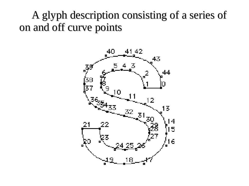
12. Outlines (Cont.)
Contours are composed of straight lines and curves.Curves are defined by a series of points that describe
second order Bezier-splines. The TrueType Bezierspline format uses two types of points to define
curves, those that are on the curve and those that
are off the curve.
Straight lines are defined by two consecutive on
curve points.
13.
A glyph description consisting of a series ofon and off curve points
14. FUnits and the em square
In a TrueType font file point locations are describedin font units, or FUnits.
An FUnit is the smallest measurable unit in the em
square, an imaginary square that is used to size and
align glyphs. The dimensions of the em square
typically are those of the full body height of a font
plus some extra spacing to prevent lines of text
from colliding when typeset without extra leading.
15.
The em squareQ
Ascent
Body
EM
Descent
A character that extends outside of the em square
f
16.
The coordinate systemy
(16383, 16383)
x
(0,0)
(-16384, -16384)
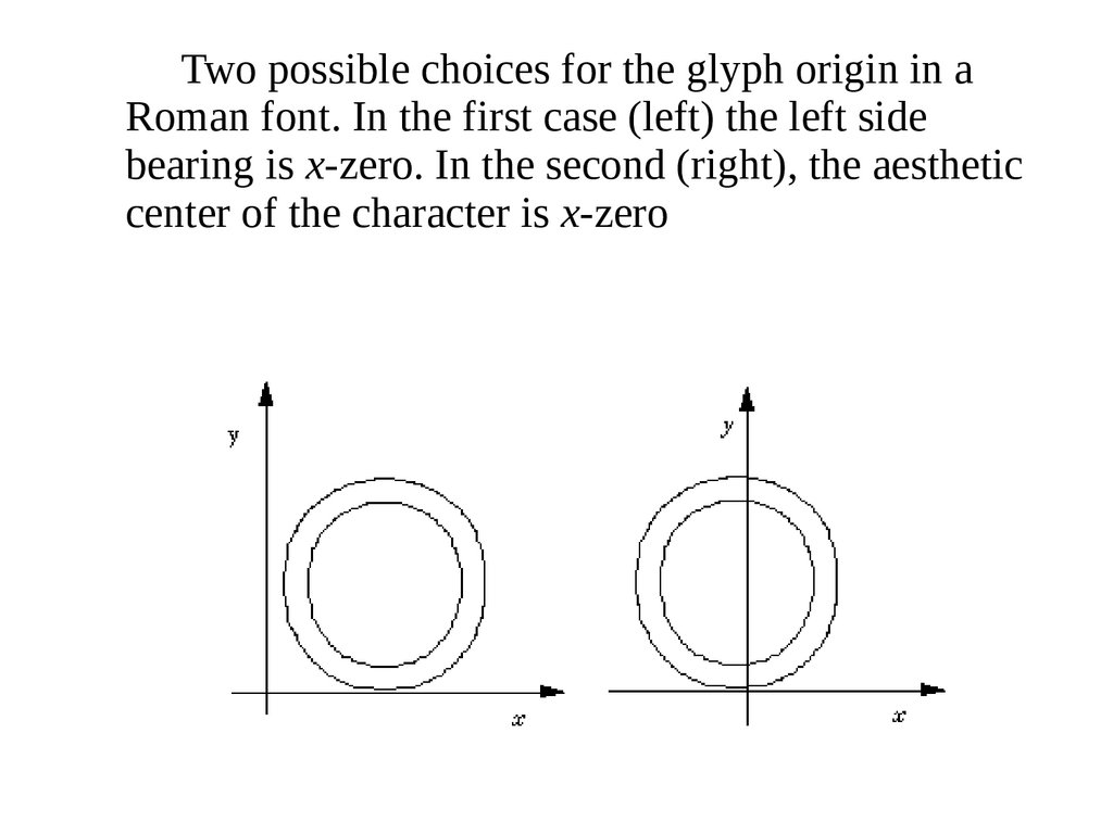
17.
Two possible choices for the glyph origin in aRoman font. In the first case (left) the left side
bearing is x-zero. In the second (right), the aesthetic
center of the character is x-zero
18. The em square
The granularity of the em square is determined by thenumber of FUnits per em, or more simply units per em.
The em square as divided into FUnits defines a
coordinate system with one unit equaling an FUnit.
All points defined in this coordinate system must have
integral locations.
The greater the number of units per em, the greater the
precision available in addressing locations within the
em square.
19.
Two em squares, 8 units per em (left), 16 units perem (right)
20. The em square (Cont.)
The number of units per em remains constantfor a given font regardless of the point size.
The number of points per em, however, will
vary with the point size of a glyph.
Since the number of units per em does not
vary with the point size at which the font is
displayed, the absolute size of an FUnit
varies as the point size varies.
21.
72 point M and 127 point M and their emsquares.
Upem equals 8 in both cases.
1 em
127 points
M M
1 em
72 points
22. The em square (Cont.)
Because FUnits are relative to the em square, a givenlocation on a glyph will have the same coordinate
location in FUnits regardless of the point size at
which the font is rendered. This is convenient
because it makes it possible to instruct outline
points once considering only the original outline
and have the changes apply to the glyph at
whatever size and resolution it is ultimately
rendered.
23. Scaling a glyph
This section describes how glyph outlines arescaled from the master size stored in the font
file to the size requested by an application.
24. Device space
Whatever the resolution of the em square used todefine a glyph outline, before that glyph can be
displayed it must be scaled to reflect the size,
transformation and the characteristics of the output
device on which it is to be displayed.
The scaled outline must describe the character outline
in units that reflect an absolute rather than relative
system of measurement.
25.
Display device characteristicsThe resolution of any particular display device
is specified by the number of dots or pixels
per inch (dpi) that are displayed.
Some devices have different resolution in the
horizontal and vertical directions (i.e. nonsquare pixels). In such cases, horizontal dots
per inch must be distinguished from vertical
dots per inch.
26. Converting FUnits to pixels
Values in the em square are converted tovalues in the pixel coordinate system by
multiplying them by a scale. This scale is:
resolution
pointSize *
72 points per inch * units_ per_ em
pointSize is the size at which the glyph is to be displayed.
resolution is the resolution of the output device.
The 72 in the denominator reflects the number of points per inch.
27. Converting FUnits to pixels (Cont.)
For example, assume that a glyph feature is550 FUnits in length on a 72 dpi screen at
18 point. There are 2048 units per em. The
following calculation reveals that the feature
is 4.83 pixels long.
18 * 72
550 *
4.83
72 * 2048
pixels
28. Grid-fitting a glyph outline
The fundamental task of instructing a glyph is one ofidentifying the critical characteristics of the
original design and using instructions to ensure
that those characteristics will be preserved when
the glyph is rendered at different sizes on different
devices. Consistent stem weights, consistent color,
even spacing, and the elimination of pixel dropouts
are common goals.
29. Grid-fitting a glyph outline
To accomplish these goals, it is necessary to ensure thatthe correct pixels are turned on when a glyph is
rasterized. It is the pixels that are turned on that create
the bitmap image of the glyph. Since it is the shape of
the glyph outline that determines which pixels will
make up the bitmap image of that character at a given
size, it is sometimes necessary to change or distort the
original outline description to produce a high quality
image. This distortion of the outline is known as gridfitting.
30. The figure below illustrates how grid-fitting a character distorts the outline found in the original design.
12 point outlines ungrid-fitted (left) and grid-fitted (right)31.
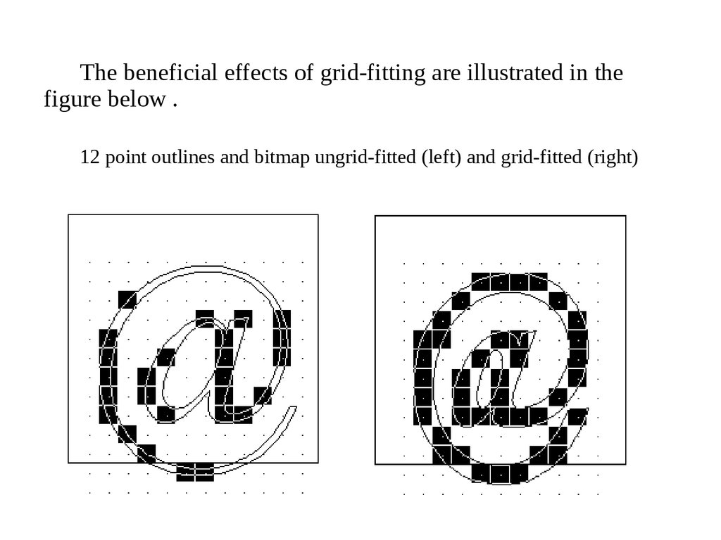
The beneficial effects of grid-fitting are illustrated in thefigure below .
12 point outlines and bitmap ungrid-fitted (left) and grid-fitted (right)
32. What are instructions?
Instructions are the mechanism by which thedesign of a character is preserved when it is
scaled. In other words, instructions control
the way in which a glyph outline will be
grid-fitted for a particular size or device.
33. TrueType Instructions
Instructing a font is a process that involves analyzingthe key elements of a glyph’s design and using the
TrueType instruction set to ensure that they are
preserved. The instructions are flexible enough to
allow characteristics that are roughly the same to
be “homogenized” at small sizes while allowing
the full flavor of the original design to emerge at
sizes where there are sufficiently many pixels.
34. The TrueType interpreter
The interpreter processes a stream or sequenceof instructions. Typically these instructions
take their arguments from the interpreter
stack and place their results on that stack.
The only exceptions are a small number of
instructions that are used to push data onto
the interpreter stack. These instructions take
their arguments from the instruction stream.
35. The TrueType interpreter (Cont.)
All of the interpreter’s actions are carried on inthe context of the Graphics State, a set of
variables whose values guide the actions of
the interpreter and determine the exact effect
of a particular instruction.
36. Using instructions
Instructions can appear in a number of placesin the font file tables that make up a
TrueType font. They can appear as part of
the Font Program, the CVT Program, or as
glyph data. Instructions appearing in the first
two apply to the font as a whole. Those
found in glyph data ('glyf') apply to
individual glyphs within a font.
37. Using instructions (Cont.)
The Font Program:Consists of a set of instructions that is executed
once, the first time a font is accessed by an
application. It is used to create function definitions
(FDEFs) and instruction definitions (IDEFs).
Functions and instructions defined in the Font
Program can be used elsewhere in the font file.
38. Using instructions (Cont.)
The CVT Program:Is a sequence of TrueType instructions executed
every time the point size or transformation change.
It is used to make font wide changes rather than to
manage individual glyphs. The CVT Program is
used to establish the values in the Control Value
Table.
The purpose of the Control Value Table or CVT
is to simplify the task of maintaining consistency
when instructing a font.
39.
Some sample CVT entriesEntry #
0
Value
0
1
2
3
4
5
-39
-35
-33
1082
1114
6
7
8
9
10
11
12
13
14
15
1493
1522
1463
1491
1493
1514
157
127
57
83
Description
upper and lower case
flat base (base line)
upper case round base
lower case round base
figure round base
x-height flat
x-height round
overlap
flat cap
round cap
numbers flat
numbers round top
flat ascender
round ascender
x stem weight
y stem weight
serif
space between the dot
and the I
40. The scan converter
The TrueType scan converter takes an outlinedescription of a glyph and produces a
bitmap image for that glyph.
The scan converter uses a simple algorithm for
determining which pixels are part of that
glyph. The rules can be stated as follows:
41. The scan converter (Cont.)
Rule 1If a pixel’s center falls within the glyph outline,
that pixel is turned on and becomes part of that
glyph.
Rule 2
If a contour falls exactly on a pixel’s center, that
pixel is turned on.
42. The scan converter (Cont.)
A point is considered to be an interior point of a glyph if it hasa non-zero winding number. The winding number is itself
determined by drawing a ray from the point in question
toward infinity. (The direction in which the ray points in
unimportant.) Starting with a count of zero, we subtract one
each time a glyph contour crosses the ray from right to left
or bottom to top. Such a crossing is termed an on transition.
We add one each time a contour of the glyph crossed the
ray from left to right or top to bottom. Such a crossing is
termed an off transition. If the final count is non-zero, the
point is an interior point.
43. Determining the winding number of a point
p1-1
p2
-1
+1
+1
-1
+1 = 0
+1 = 1
44. What is a dropout?
A dropout occurs whenever there is aconnected region of a glyph interior that
contains two black pixels that cannot be
connected by a straight line that only passes
through black pixels.
45.
The letter m with two dropouts46. Preventing dropouts
Rule 3If a scan line between two adjacent pixel centers
(either vertical or horizontal) is intersected by both
an on-Transition contour and an off-Transition
contour and neither of the pixels was already
turned on by rules 1 and 2, turn on the left-most
pixel (horizontal scan line) or the bottom-most pixel
(vertical scan line)
47. Preventing dropouts
Rule 4Apply Rule 3 only if the two contours continue to
intersect other scan lines in both directions. That is do not
turn on pixels for 'stubs'. The scanline segments that form a
square with the intersected scan line segment are examined
to verify that they are intersected by two contours. It is
possible that these could be different contours than the ones
intersecting the dropout scan line segment. This is very
unlikely but may have to be controlled with grid-fitting in
some exotic glyphs.