


 industry
 advertising
Similar presentations:
")


Training course antenna and pedestal group (apg)
1.
TRAINING COURSEANTENNA AND PEDESTAL GROUP
(APG)
Primary Surveillance Radar Systems
ATM
Nº doc.: 0066605020000MA03
Edición: A Revisión: 1
Fecha: 09/03/2020
2.
Warning of ConfidentialityThe data and information, in its totality or partial expression, contained in this document are property of
Indra Sistemas, S.A. This data and information cannot be disclosed totally or partially to third parties.
The copy, reproduction, public communication, dissemination, total or partial distribution, modification or
assignment will require the prior written authorization of Indra Sistemas, S.A. Its content cannot be used
for different purposes to those for which it is provided, its use being limited to the execution of the
Program it is supplied for.
0066605020000MA03 _A1
09/03/2020
2 de 722
3.
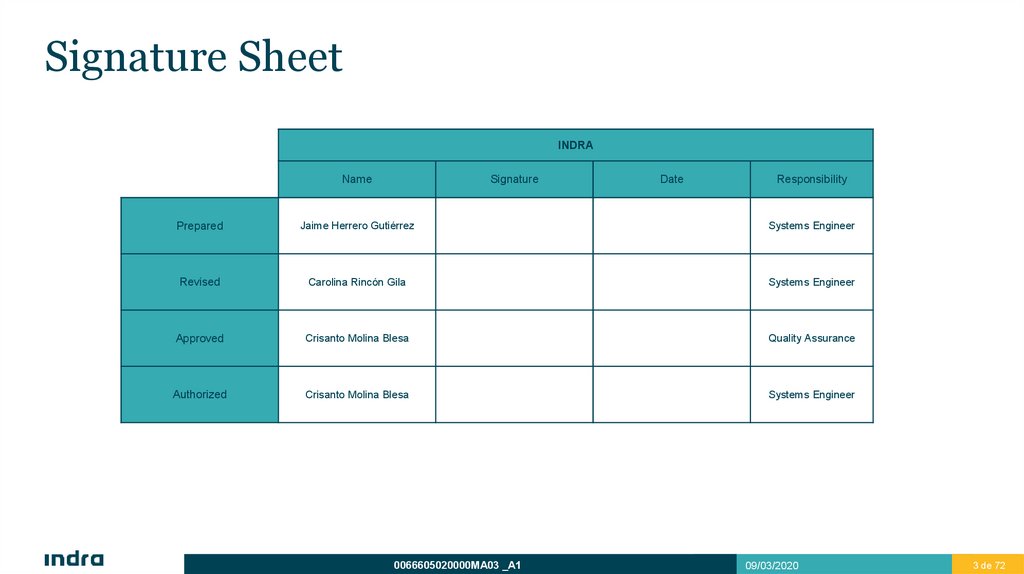
Signature SheetINDRA
Name
Signature
Date
Responsibility
Prepared
Jaime Herrero Gutiérrez
Systems Engineer
Revised
Carolina Rincón Gila
Systems Engineer
Approved
Crisanto Molina Blesa
Quality Assurance
Authorized
Crisanto Molina Blesa
Systems Engineer
0066605020000MA03 _A1
09/03/2020
3 de 723
4.
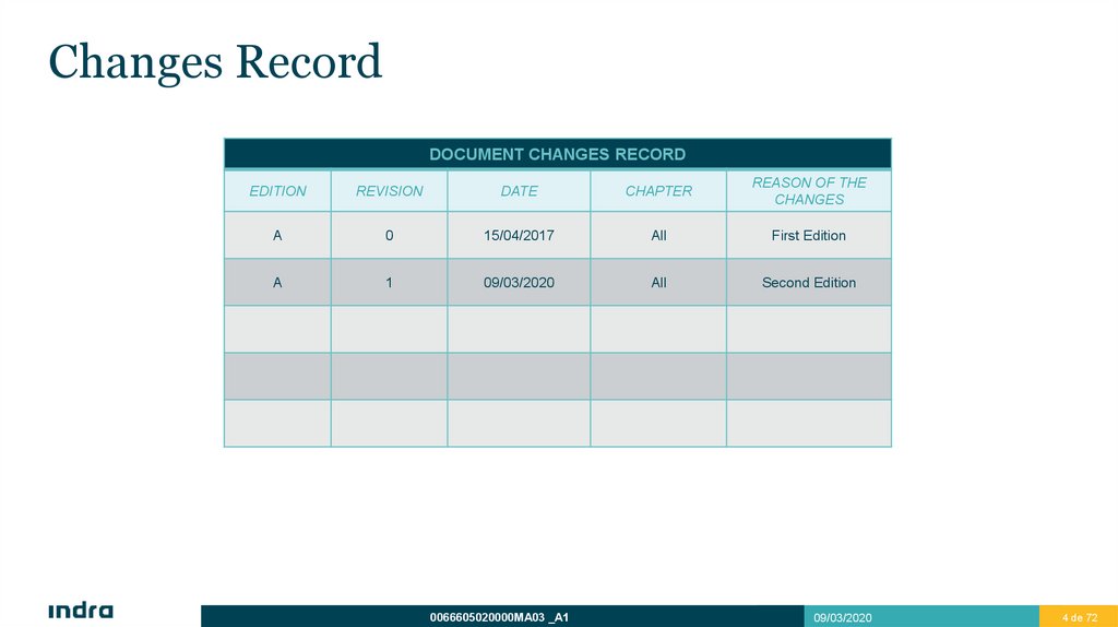
Changes RecordDOCUMENT CHANGES RECORD
EDITION
REVISION
DATE
CHAPTER
REASON OF THE
CHANGES
A
0
15/04/2017
All
First Edition
A
1
09/03/2020
All
Second Edition
0066605020000MA03 _A1
09/03/2020
4 de 724
5.
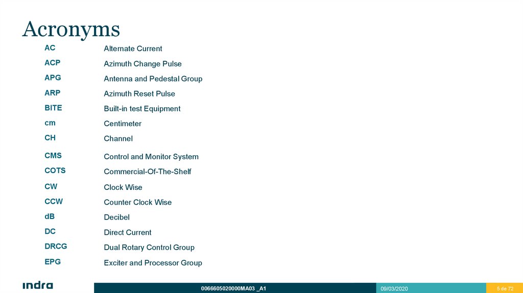
AcronymsAC
Alternate Current
ACP
Azimuth Change Pulse
APG
Antenna and Pedestal Group
ARP
Azimuth Reset Pulse
BITE
Built-in test Equipment
cm
Centimeter
CH
Channel
CMS
Control and Monitor System
COTS
Commercial-Of-The-Shelf
CW
Clock Wise
CCW
Counter Clock Wise
dB
Decibel
DC
Direct Current
DRCG
Dual Rotary Control Group
EPG
Exciter and Processor Group
0066605020000MA03 _A1
09/03/2020
5 de 725
6.
AcronymsEMC
Electromagnetic Compatibility
GHz
Gigahertz
h
Hour
Hz
Hertz
Kg
Kilogram
Km
Kilometer
Kw
Kilowatt
KVA
Kilovoltamper
LAN
Local Area Network
LVA
Large Vertical Aperture
m
Meter
mm
millimeter
MSSR
Monopulse Secondary Surveillance Radar
NLFM
Non Lineal Frequency Modulation
NM (nmi)
Nautical Miles
0066605020000MA03 _A1
09/03/2020
6 de 726
7.
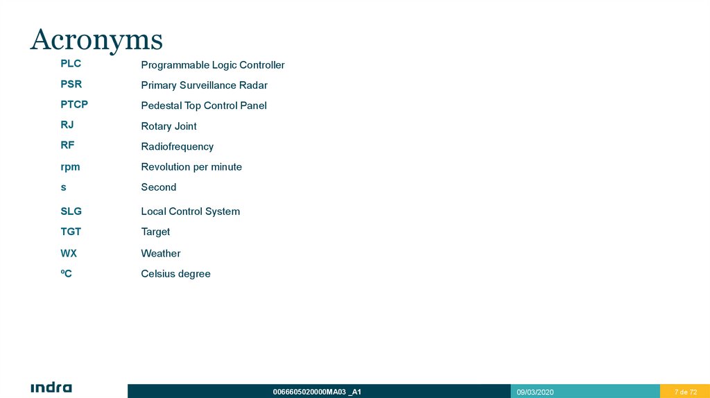
AcronymsPLC
Programmable Logic Controller
PSR
Primary Surveillance Radar
PTCP
Pedestal Top Control Panel
RJ
Rotary Joint
RF
Radiofrequency
rpm
Revolution per minute
s
Second
SLG
Local Control System
TGT
Target
WX
Weather
ºC
Celsius degree
0066605020000MA03 _A1
09/03/2020
7 de 727
8.
IndexIntroduction
Block Diagram
Functional Description and elements
System composition
APG Physical and Functional Description
Antenna
Pedestal
Rotary Joint
1
2
9.
IndexDRCG Physical and Functional Description
Main Features
Elements and Diagrams
BITE
Operation
Features
Pedestal Top Control Panel (PTCP)
Junction Box
APG Interfaces
Antenna
Pedestal
Rotary Joint
3
4
10.
IntroductionBlock Diagram
Functional Description and elements
System composition
1
11.
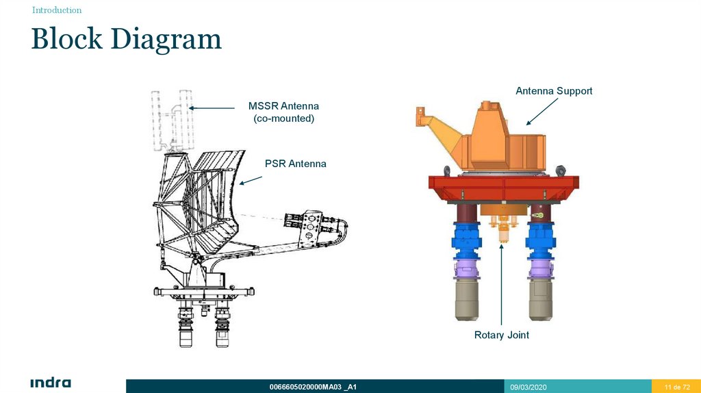
IntroductionBlock Diagram
Antenna Support
MSSR Antenna
(co-mounted)
PSR Antenna
Rotary Joint
0066605020000MA03 _A1
09/03/2020
11 de 72
11
12.
IntroductionFunctional Description and Elements
Antenna subsystem transmits and receives RF signals and consists of:
A reflector.
Two feedhorns.
Polarizer.
Pedestal subsystem performs antenna rotation and consists of:
Two motors.
Two gearboxes.
Two Electrical Clutches.
Rotary joint subsystem consists of a fixed and a moving part and provides:
7 RF channels:
4 for PSR (2 for TGT in waveguide and 2 for WX in coaxial)
3 for MSSR (coaxial)
18 AC/DC slip-rings.
2 encoders.
The rotary joint is the interface between the APG and the sensor (for transmission and reception).
Reception: coaxial cable for weather low/high beams. Waveguide for target high beam and target low beam.
Transmission: Waveguide through low beam path.
The high target channel is directed to the sensor through coaxial by means of a coupler after the rotatory joint.
0066605020000MA03 _A1
09/03/2020
12 de 72
12
13.
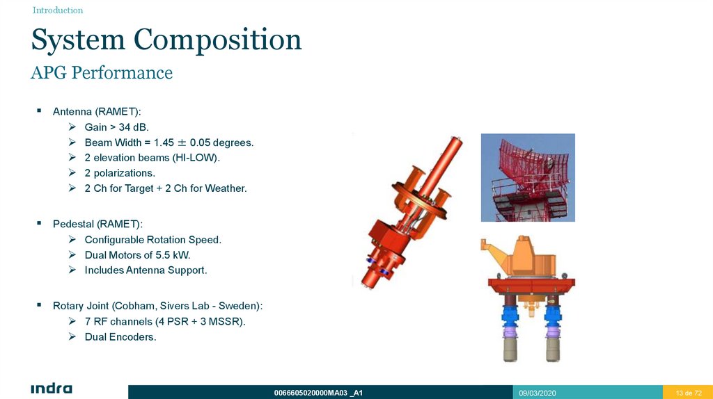
IntroductionSystem Composition
APG Performance
Antenna (RAMET):
Gain > 34 dB.
Beam Width = 1.45 ± 0.05 degrees.
2 elevation beams (HI-LOW).
2 polarizations.
2 Ch for Target + 2 Ch for Weather.
Pedestal (RAMET):
Configurable Rotation Speed.
Dual Motors of 5.5 kW.
Includes Antenna Support.
Rotary Joint (Cobham, Sivers Lab - Sweden):
7 RF channels (4 PSR + 3 MSSR).
Dual Encoders.
0066605020000MA03 _A1
09/03/2020
13 de 72
13
14.
APG Physical andFunctional Description
Antenna
Pedestal
Rotary Joint
2
15.
APG Physical and Functional DescriptionAntenna
0066605020000MA03 _A1
09/03/2020
15 de 72
15
16.
APG Physical and Functional DescriptionAntenna
Introduction
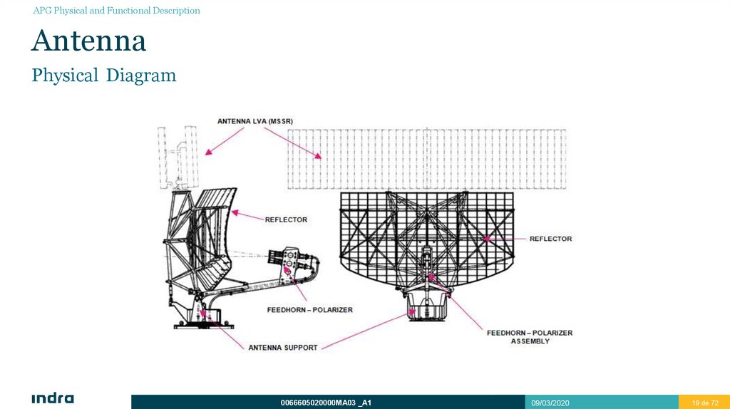
Antenna subsystem is a COTS element made by RAMET and performs RF signal transmission and reception in S-band (2.7 a 2.9 GHz).
This subsystem is made up the next elements:
Reflector, provides an square cosecant elevation pattern.
Two feedhorn assembly, the top one (low beam) transmits and receives, and the bottom one (high beam), only receives.
Two polarizers, provides vertical linear and right-hand circular polarization (transmission and reception).
Two target channels (w/g) and two weather channels (coaxial).
Mechanical Tilt.
In addition, it is made by optional elements such as:
Possibility of co-mounting a LVA antenna.
An obstruction light.
A lightning rod.
Polarization changing and antenna turning monitoring.
0066605020000MA03 _A1
09/03/2020
16 de 72
16
17.
APG Physical and Functional DescriptionPedestal
Features
ELECTRIC REQUIREMENTS
Pinion:
Features
Steel
Bearing Ring - Fixed Case:
Features
Dual motor, possibility of operation with one motor
Sensors
Oil level
Bearing Ring - Mobile Case:
Features
Mechanical interface for S-Band PSR antenna.
Features
4 anchoring points and leveling points to adjust antenna tilt.
Antenna Support:
Features
Mechanical interface between antenna and driving mechanism.
0066605020000MA03 _A1
09/03/2020
17 de 72
17
18.
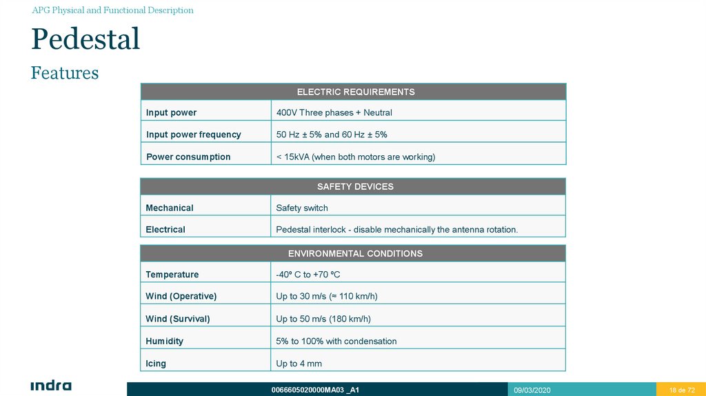
APG Physical and Functional DescriptionPedestal
Features
ELECTRIC REQUIREMENTS
Input power
400V Three phases + Neutral
Input power frequency
50 Hz ± 5% and 60 Hz ± 5%
Power consumption
< 15kVA (when both motors are working)
SAFETY DEVICES
Mechanical
Safety switch
Electrical
Pedestal interlock - disable mechanically the antenna rotation.
ENVIRONMENTAL CONDITIONS
Temperature
-40º C to +70 ºC
Wind (Operative)
Up to 30 m/s (≈ 110 km/h)
Wind (Survival)
Up to 50 m/s (180 km/h)
Humidity
5% to 100% with condensation
Icing
Up to 4 mm
0066605020000MA03 _A1
09/03/2020
18 de 72
18
19.
APG Physical and Functional DescriptionAntenna
Physical Diagram
0066605020000MA03 _A1
09/03/2020
19 de 72
19
20.
APG Physical and Functional DescriptionAntenna
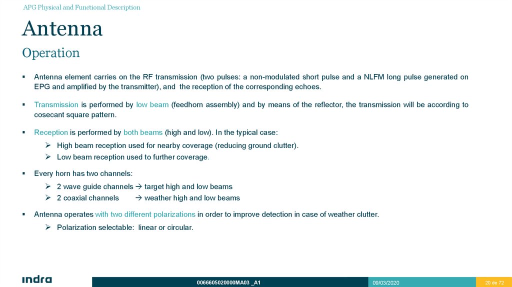
Operation
Antenna element carries on the RF transmission (two pulses: a non-modulated short pulse and a NLFM long pulse generated on
EPG and amplified by the transmitter), and the reception of the corresponding echoes.
Transmission is performed by low beam (feedhorn assembly) and by means of the reflector, the transmission will be according to
cosecant square pattern.
Reception is performed by both beams (high and low). In the typical case:
High beam reception used for nearby coverage (reducing ground clutter).
Low beam reception used to further coverage.
Every horn has two channels:
2 wave guide channels target high and low beams
2 coaxial channels
weather high and low beams
Antenna operates with two different polarizations in order to improve detection in case of weather clutter.
Polarization selectable: linear or circular.
0066605020000MA03 _A1
09/03/2020
20 de 72
20
21.
APG Physical and Functional DescriptionAntenna
Azimuth Diagram
0066605020000MA03 _A1
09/03/2020
21 de 72
21
22.
APG Physical and Functional DescriptionAntenna
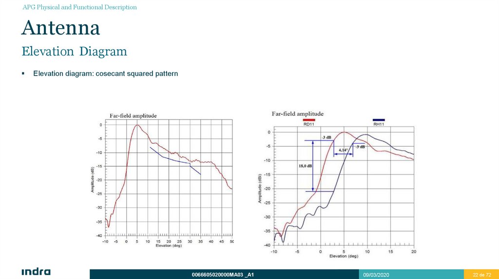
Elevation Diagram
Elevation diagram: cosecant squared pattern
0066605020000MA03 _A1
09/03/2020
22 de 72
22
23.
APG Physical and Functional DescriptionAntenna
Polarization
PSR antenna can transmit with two different polarizations.
Features:
Transmission polarization:
Linear vertical.
Right handed circular E clockwise rotation.
Polarizer transmits and receives linear or circular polarization.
0066605020000MA03 _A1
09/03/2020
23 de 72
23
24.
APG Physical and Functional DescriptionAntenna
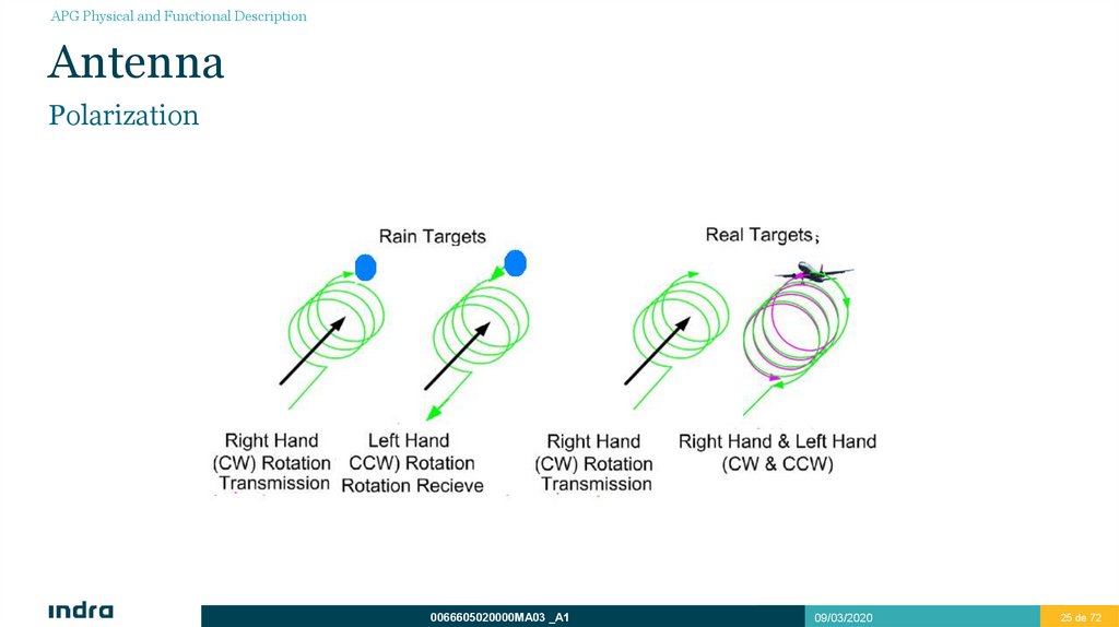
Polarization
POLARIZATION ADVANTAGES.
Symmetric objects (such as raindrops):
Reflects circularly-polarized waves with the opposite sense of rotation. There is one reflection of the wave.
Reflects lineal polarization in the same sense as it was sent.
Asymmetrical objects (such as aircraft):
Reflects circularly-polarized waves with the same and the opposite sense of rotation because they are odd and even
numbers of reflections.
Reflects lineal polarization in the same sense as it was sent.
Notice that transmitted circular polarization:
3 dB of losses in target echoes.
>20 dB in spherical target echoes.
0066605020000MA03 _A1
09/03/2020
24 de 72
24
25.
APG Physical and Functional DescriptionAntenna
Polarization
0066605020000MA03 _A1
09/03/2020
25 de 72
25
26.
APG Physical and Functional DescriptionAntenna
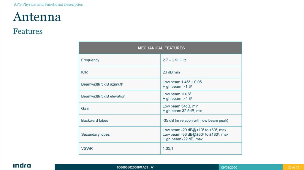
Features
MECHANICAL FEATURES
Frequency
2.7 – 2.9 GHz
ICR
20 dB min
Beamwidth 3 dB azimuth
Low beam 1.45º ± 0.05
High beam >1.3º
Beamwidth 3 dB elevation
Low beam >4.6º
High beam >4.8º
Gain
Low beam 34dB, min
High beam 32.5dB, min
Backward lobes
-35 dB (in relation with low beam peak)
Secondary lobes
Low beam -29 dB@±10º to ±30º, max
Low beam -33 dB@±30º to ±180º, max
High beam -22 dB, max
VSWR
1.35:1
0066605020000MA03 _A1
09/03/2020
26 de 72
26
27.
APG Physical and Functional DescriptionAntenna
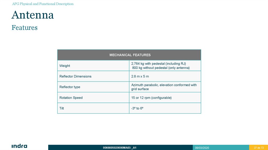
Features
MECHANICAL FEATURES
Weight
2,764 kg with pedestal (including RJ)
800 kg without pedestal (only antenna)
Reflector Dimensions
2.8 m x 5 m
Reflector type
Azimuth parabolic, elevation conformed with
grid surface
Rotation Speed
15 or 12 rpm (configurable)
Tilt
-3º to 6º
0066605020000MA03 _A1
09/03/2020
27 de 72
27
28.
APG Physical and Functional DescriptionPedestal
0066605020000MA03 _A1
09/03/2020
28 de 72
28
29.
APG Physical and Functional DescriptionPedestal
Introduction
Pedestal:
Electromechanical system which able to give continuous rotation to the antenna.
Consists of a mobile case mounted on a large bearing and supported in its base by a fixed case which, at the same time,
supports both power lines (motor + Electrical Clutch).
The pedestal shall allow the assembly of a rotary joint that transmits and receives the RF signals, AC/DC signals and angular
transmission signals from the fixed case to the mobile case.
0066605020000MA03 _A1
09/03/2020
29 de 72
29
30.
APG Physical and Functional DescriptionPedestal
Physical Diagram
0066605020000MA03 _A1
09/03/2020
30 de 72
30
31.
APG Physical and Functional DescriptionPedestal
Description and Elements
The pedestal subsystem is a electromechanical system which performs continuous antenna rotation (even with a co-mounted MSSR
antenna).
The system consists of the next elements:
Movement transmitter system:
Two 5.5 kW motors with gearbox + coupling Electrical Clutch + pinion and bearing ring.
Intermediate element:
Connects the frame and the antenna drive mechanism with the antenna support.
Electrical and Mechanical interfaces:
Each motor has a Heating and a Thermistor terminal.
Oil level sensor.
Antenna Locking:
Antenna can be locked at any angle by the locking screw.
Interlocks:
Electrical: Pedestal Interlock.
Mechanical: Safety Switch.
0066605020000MA03 _A1
09/03/2020
31 de 72
31
32.
APG Physical and Functional DescriptionPedestal
Operation
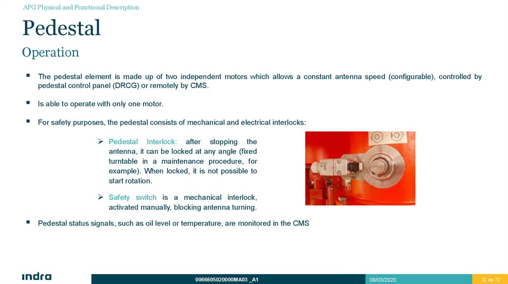
The pedestal element is made up of two independent motors which allows a constant antenna speed (configurable), controlled by
pedestal control panel (DRCG) or remotely by CMS.
Is able to operate with only one motor.
For safety purposes, the pedestal consists of mechanical and electrical interlocks:
Pedestal
Interlock: after stopping the
antenna, it can be locked at any angle (fixed
turntable in a maintenance procedure, for
example). When locked, it is not possible to
start rotation.
Safety switch is a mechanical interlock,
activated manually, blocking antenna turning.
Pedestal status signals, such as oil level or temperature, are monitored in the CMS
0066605020000MA03 _A1
09/03/2020
32 de 72
32
33.
APG Physical and Functional DescriptionPedestal
Lubrication System
Oil bath for turntable lubrication and for each drive train reducer.
Long-life synthetic oil used as lubricant.
Oil heaters to correct operation: gearbox and motors.
Sensors to monitor oil level and temperature.
Status reporting to DRCG:
Over Temperature.
Oil low level.
0066605020000MA03 _A1
09/03/2020
33 de 72
33
34.
APG Physical and Functional DescriptionPedestal
Lubrication System
ADM Bearing
Oil Sealing
0066605020000MA03 _A1
09/03/2020
34 de 72
34
35.
APG Physical and Functional DescriptionPedestal
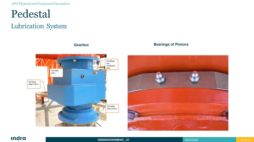
Lubrication System
Bearings of Pinions
Gearbox
0066605020000MA03 _A1
09/03/2020
35 de 72
35
36.
APG Physical and Functional DescriptionPedestal
Lubrication System
UNIT
FREQUENCY
LUBRICATION TYPE
FILL QUANTITY
Gearbox
12500 hours or 2 years
Shell Omala S4 GX150
or equivalent
7.5 liters
ADM Bearing
12500 hours or 2 years
Castrol Alphasyn GS 220
9.33 liters
Pin Coupling
20000 hours or 2 years
Aero Shell Grease 6
As required
0066605020000MA03 _A1
09/03/2020
36 de 72
36
37.
APG Physical and Functional DescriptionPedestal
Features
MOTOR UNIT
Number of drives
2 redundant driving lines composed of the following elements each one: (1 motor,
1 gearbox, 1 Electrical Clutch and 1 pinion) and one bearing ring. Motor
controllers necessary for speed adjustment.
Rotation speed
12 or 15 revolutions per minute, adjustable.
Motor/s:
Output power
5.5 kW
Features
Equipped with heating elements. Possibility to change motors whitout stopping
the antenna.
Sensors
Over temperature
Gearbox:
Lubrication
Oil sight glass
Features
Two-helical gearboxes
Electrical Clutch:
Sensors
Electrical Clutch Engaged/Disengaged
Features
Maximum torque 200 N.m
Features
Possibility of engage/disengage while rotation
0066605020000MA03 _A1
09/03/2020
37 de 72
37
38.
APG Physical and Functional DescriptionPedestal – Electromechanical Clutch
Features
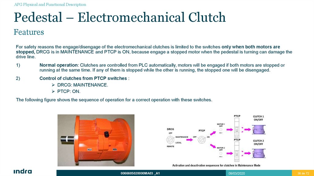
For safety reasons the engage/disengage of the electromechanical clutches is limited to the switches only when both motors are
stopped, DRCG is in MAINTENANCE and PTCP is ON, because engage a stopped motor when the pedestal is turning can damage the
drive line.
1)
Normal operation: Clutches are controlled from PLC automatically, motors will be engaged if both motors are stopped or
running at the same time. If any of them is stopped while the other is running, the stopped one will be disengaged.
2)
Control of clutches from PTCP switches :
DRCG: MAINTENANCE.
PTCP: ON.
The following figure shows the sequence of operation for a correct operation with these switches.
0066605020000MA03 _A1
09/03/2020
38 de 72
38
39.
APG Physical and Functional DescriptionRotary Joint
0066605020000MA03 _A1
09/03/2020
39 de 72
39
40.
APG Physical and Functional DescriptionRotary Joint
Introduction
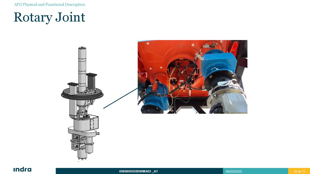
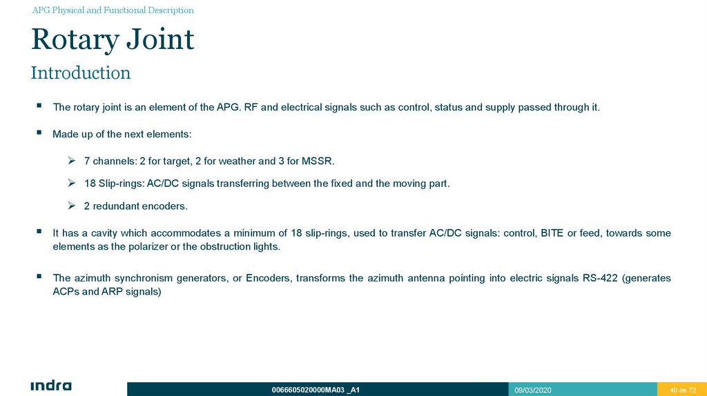
The rotary joint is an element of the APG. RF and electrical signals such as control, status and supply passed through it.
Made up of the next elements:
7 channels: 2 for target, 2 for weather and 3 for MSSR.
18 Slip-rings: AC/DC signals transferring between the fixed and the moving part.
2 redundant encoders.
It has a cavity which accommodates a minimum of 18 slip-rings, used to transfer AC/DC signals: control, BITE or feed, towards some
elements as the polarizer or the obstruction lights.
The azimuth synchronism generators, or Encoders, transforms the azimuth antenna pointing into electric signals RS-422 (generates
ACPs and ARP signals)
0066605020000MA03 _A1
09/03/2020
40 de 72
40
41.
APG Physical and Functional DescriptionRotary Joint
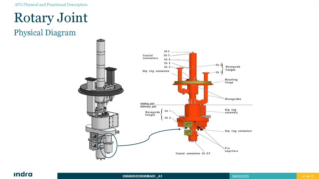
Physical Diagram
0066605020000MA03 _A1
09/03/2020
41 de 72
41
42.
APG Physical and Functional DescriptionRotary Joint
Operation
RF signals are transmitted through antenna Low Beam (waveguide, specified to tolerate high peak power) and received through both
beams.
High beam signal passes through waveguide in the antenna and rotary joint, and sent to the system through coaxial by means of
a waveguide-coaxial coupler after the rotary joint.
In addition, MSSR channels can pass through rotary joint.
The slip-rings are a set of AC/DC rings where status, control and supply signals passes through, from DRCG to the antenna.
These signals are:
Polarizer status signals for both beams.
Polarizer control signals.
Obstruction light supplied signals.
0066605020000MA03 _A1
09/03/2020
42 de 72
42
43.
APG Physical and Functional DescriptionRotary Joint
Slip-Rings
0066605020000MA03 _A1
09/03/2020
43 de 72
43
44.
APG Physical and Functional DescriptionRotary Joint
Slip-Rings
0066605020000MA03 _A1
09/03/2020
44 de 72
44
45.
APG Physical and Functional DescriptionRotary Joint
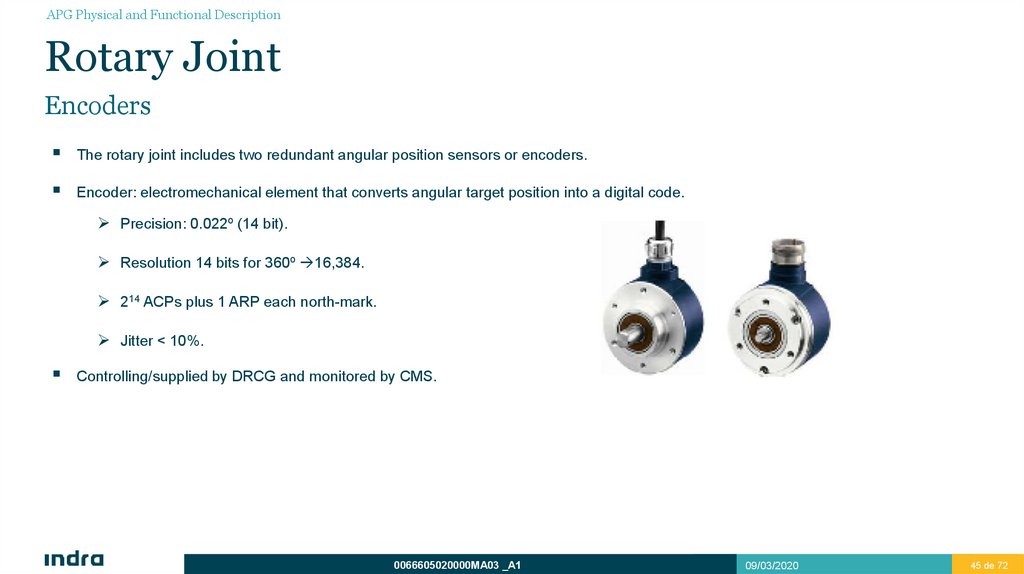
Encoders
The rotary joint includes two redundant angular position sensors or encoders.
Encoder: electromechanical element that converts angular target position into a digital code.
Precision: 0.022º (14 bit).
Resolution 14 bits for 360º 16,384.
214 ACPs plus 1 ARP each north-mark.
Jitter < 10%.
Controlling/supplied by DRCG and monitored by CMS.
0066605020000MA03 _A1
09/03/2020
45 de 72
45
46.
APG Physical and Functional DescriptionRotary Joint
Features
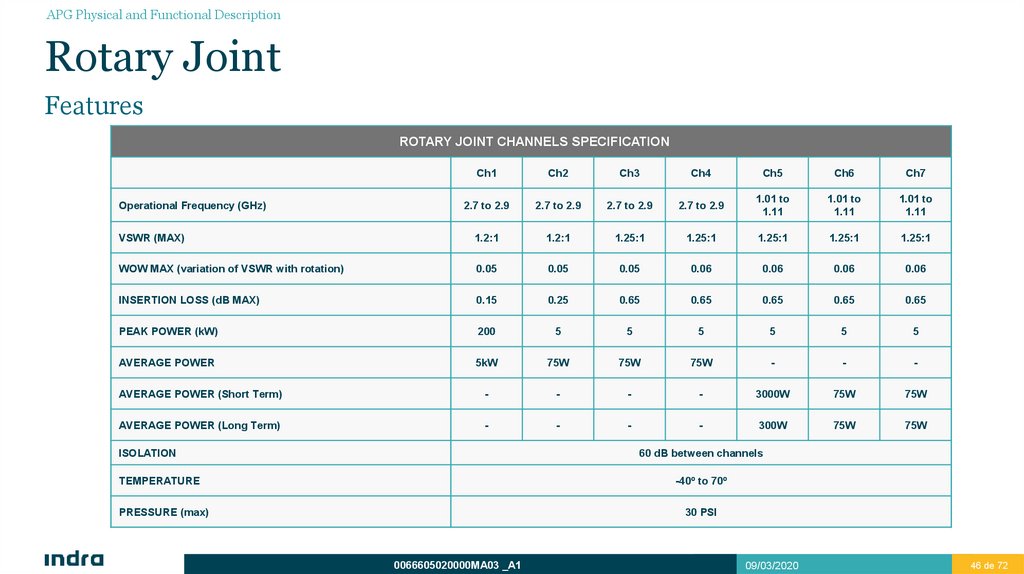
ROTARY JOINT CHANNELS SPECIFICATION
Ch1
Ch2
Ch3
Ch4
Ch5
Ch6
Ch7
2.7 to 2.9
2.7 to 2.9
2.7 to 2.9
2.7 to 2.9
1.01 to
1.11
1.01 to
1.11
1.01 to
1.11
VSWR (MAX)
1.2:1
1.2:1
1.25:1
1.25:1
1.25:1
1.25:1
1.25:1
WOW MAX (variation of VSWR with rotation)
0.05
0.05
0.05
0.06
0.06
0.06
0.06
INSERTION LOSS (dB MAX)
0.15
0.25
0.65
0.65
0.65
0.65
0.65
PEAK POWER (kW)
200
5
5
5
5
5
5
AVERAGE POWER
5kW
75W
75W
75W
-
-
-
AVERAGE POWER (Short Term)
-
-
-
-
3000W
75W
75W
AVERAGE POWER (Long Term)
-
-
-
-
300W
75W
75W
Operational Frequency (GHz)
ISOLATION
60 dB between channels
-40º to 70º
TEMPERATURE
PRESSURE (max)
30 PSI
0066605020000MA03 _A1
09/03/2020
46 de 72
46
47.
APG Physical and Functional DescriptionRotary Joint
Features
GENERAL SPECIFICATIONS
Isolation
60 dB between channels, minimum
Max. Radiation during the peak of power @ a
distance of 0,2 m.
0.1 mW/cm2
Total weight
< 80 Kg
Height of rotary part
According to the pedestal
Height of the stationary part
According to the pedestal
Temperature range (operative)
-40º C to +70º C
Temperature range (storage)
-40º C to +70º C
Pressurization
30 PSI max.
Leakage
25cc/min MAX @ 5 PSI operational temperature range @ 10,000 feet over sea level
Rotation speed
15 rpm max.
0066605020000MA03 _A1
09/03/2020
47 de 72
47
48.
APG Physical and Functional DescriptionRotary Joint
Features
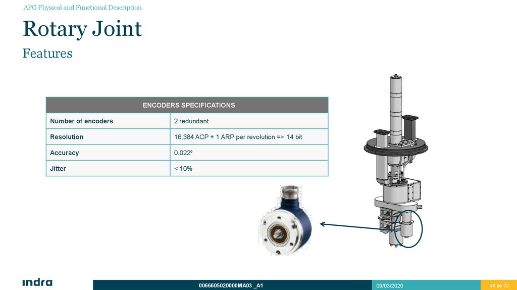
ENCODERS SPECIFICATIONS
Number of encoders
2 redundant
Resolution
16,384 ACP + 1 ARP per revolution => 14 bit
Accuracy
0.022º
Jitter
< 10%
0066605020000MA03 _A1
09/03/2020
48 de 72
48
49.
DRCG Physical andFunctional Description
Main Features
Elements and Diagrams
BITE
Operation
Features
Pedestal Top Control Panel (PTCP)
Junction Box
3
50.
DRCG Physical and Functional DescriptionDRCG Elements and Diagrams
Front Diagram
Local/Remote control
Inhibit Selector
Emergency Stop
Motors ON/OFF
0066605020000MA03 _A1
09/03/2020
50 de 72
50
51.
DRCG Physical and Functional DescriptionMain Features
Performs Antenna and Pedestal Group control and monitoring.
Supplies the energy required to encoders and polarizer.
It has been designed with a safety chain and different control modes: Local, Remote or Maintenance.
Protects all lines, for both data and power, established between the radar head and the equipment installed in the tower, from
possible overvoltages caused by lightning.
Apart from monitoring the status of the equipment connected to the DRCG, it is reported to CMS via LAN communication.
Controls the antenna turning speed by means of controllers.
0066605020000MA03 _A1
09/03/2020
51 de 72
51
52.
DRCG Physical and Functional DescriptionFeatures
Power Supply
Control Panel
Motor Controllers
Power Supplies
PLC/ programmable switch
Communication
Safety
Operation Modes
400 VAC, 60 A, 50/60 Hz
Pedestal status or motor on-off (possibility to operate
with one or two motors) monitoring.
Converts input alternate current into direct current to be
converted in alternate current again later but with a
frequency adjustment to 12 or 15 rpm depending on
system configuration.
24 VDC redundant
For supply PLC, LEDs, encoders…
24 inputs
19 outputs
Two modules for redundant transmission Modbus/TCP
Switch to implement the safety chain
Emergency button to emergency stopping.
LOCAL: Starting up from DRCG
MAINTENANCE: Allows the key to be removed from the
control panel front
REMOTE: Starting up from SLG
0066605020000MA03 _A1
09/03/2020
52 de 72
52
53.
DRCG Physical and Functional DescriptionElements and Diagrams
Internal Diagrams
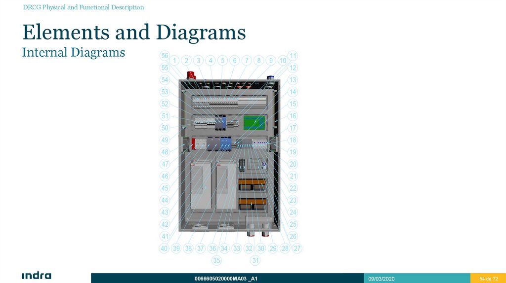
It is made up of the next elements, among others:
Circuit breakers to control the supply of the different elements.
Electrical protection devices: AC and DC protection.
Two redundant modules to perform communication (acquisition data module): Receive and transmit the status signals
(received as 24 Vdc voltage) and performs BITE management by means of ModBus/TCP protocol.
Diodes board: To avoid undesired current returns.
Two motor controllers: Transforms alternate current into direct current in order to convert it later into alternate but varying its
frequency to the determined value. Controls antenna turning speed and motor status.
A PLC/programmable relay: Controls status signals managed by the DRCG.
Two EMC filters: One for each driving line, responsible for attenuating undesired harmonic frequencies.
At the front panel: Monitors pedestal status, switching motors on/off etc.
0066605020000MA03 _A1
09/03/2020
53 de 72
53
54.
DRCG Physical and Functional DescriptionElements and Diagrams
Internal Diagrams
0066605020000MA03 _A1
09/03/2020
54 de 72
54
55.
DRCG Physical and Functional DescriptionElements and Diagrams
Internal Diagrams
1
2
3
4
5
RPS
CB2
CB3
CB4
CB5
6
7
8
9
10
11
12
13
14
CB6
CB7
CB8
CB9
RV
TB1
F1 a F5
DPCB
TB2
15
16
17
18
19
20
21
22
23
24
CB14
E3
K9
K10
B2
K8
K7
K6
K5
S11
Redundancy module for 24V Power Supplies
Main breaker 2
Breaker for motor 1 heater
Breaker for motor 2 heater
Breaker for start-up warning, dusk sensor and
obstruction lights
Breaker for fan B1
Breaker for fan B2
Breaker for power supply for clutch 2
Breaker for power supply for clutch 1
Overvoltage Dischargers.
24 VDC and 0 VDC distribution terminals
Protection fuses for 24 VDC
DRCG interconnection board
Polarizer power supply and control distribution
terminals
Breaker for polarizer power supply 1
Ground for dischargers.
Clutch 2 activation relay
Clutch 2 heater activation relay
Right side fan
Clutch 1 heater activation relay
Clutch 2 activation relay
Obstruction lights activation relay
Polarization control contactor
Thermostat for fans
0066605020000MA03 _A1
09/03/2020
55 de 72
55
56.
DRCG Physical and Functional DescriptionElements and Diagrams
Internal Diagrams
25
26
27
28
29
30
31
32
33
34
35
36
37
38
39
40
K4
S10
PLC
KB1
S9
S8
KB2
SW2
S7
SW1
DRV2
S6
CB16
CB15
DRV1
RDC
41
42
43
44
45
46
47
48
DC2
DC1
PS4
PS3
K3
K2
K1
B1
Polarizer control activation relay
Switch for Motor 2 Heater
Programmable Logic Controller
16 channels relays module 1
Switch for Motor 1 Heater
Switch for Encoder 2
16 channels relays module 2
Switch router 2
Switch for Encoder 1
Switch router 1
Motor Controller 2
Obstruction lights switch
Breaker for anemometer power supply
Breaker for polarizer 2 power supply
Motor Controller 1
Redundancy Module for DC converter of power supply
for polarizer
DC converter power supply for polarizer 2
DC converter power supply for polarizer 1
Clutch 2 power supply
Clutch 1 power supply
Motor Controller 2 Contactor
Motor Controller 1 Contactor
Safety relay
Left side fan
0066605020000MA03 _A1
49
E2
50
51
52
53
54
55
56
CB10
CB11
CB12
CB13
PS1
PS2
CB1
Ground bar for connectors and other elements (except
dischargers)
Breaker for Motor Controller 1
Breaker for Motor Controller 2
Breaker for Power Supply 1
Breaker for Power Supply 2
24 VDC Power Suply 1
24 VDC Power Supply 2
Main breaker
09/03/2020
56 de 72
56
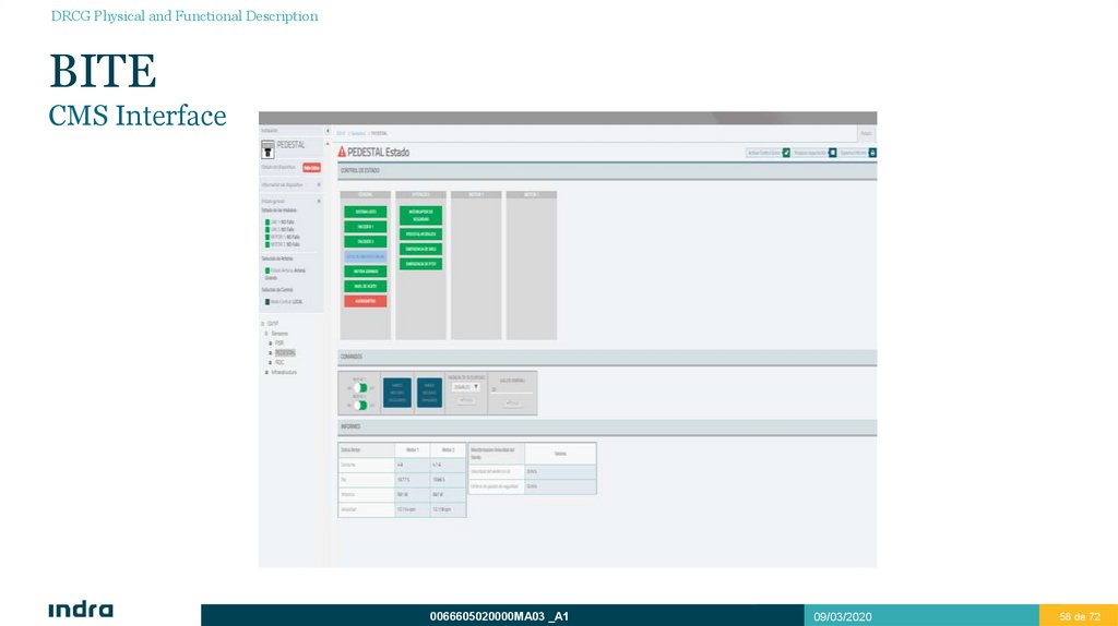
57.
DRCG Physical and Functional DescriptionBITE
Connection
BITE signals coming from Antenna and Pedestal Group, are
managed by means of the PLC firmware. These signals are
pedestal status, equipment control, interlocks and controllers
status signals.
All signals are received and packed by means of acquisition
data modules. These signals are transmitted by means of
Modbus/TCP protocol through two redundant LAN.
0066605020000MA03 _A1
09/03/2020
57 de 72
57
58.
DRCG Physical and Functional DescriptionBITE
CMS Interface
0066605020000MA03 _A1
09/03/2020
58 de 72
58
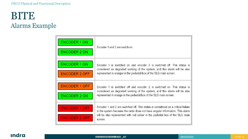
59.
DRCG Physical and Functional DescriptionBITE
Alarms Example
0066605020000MA03 _A1
09/03/2020
59 de 72
59
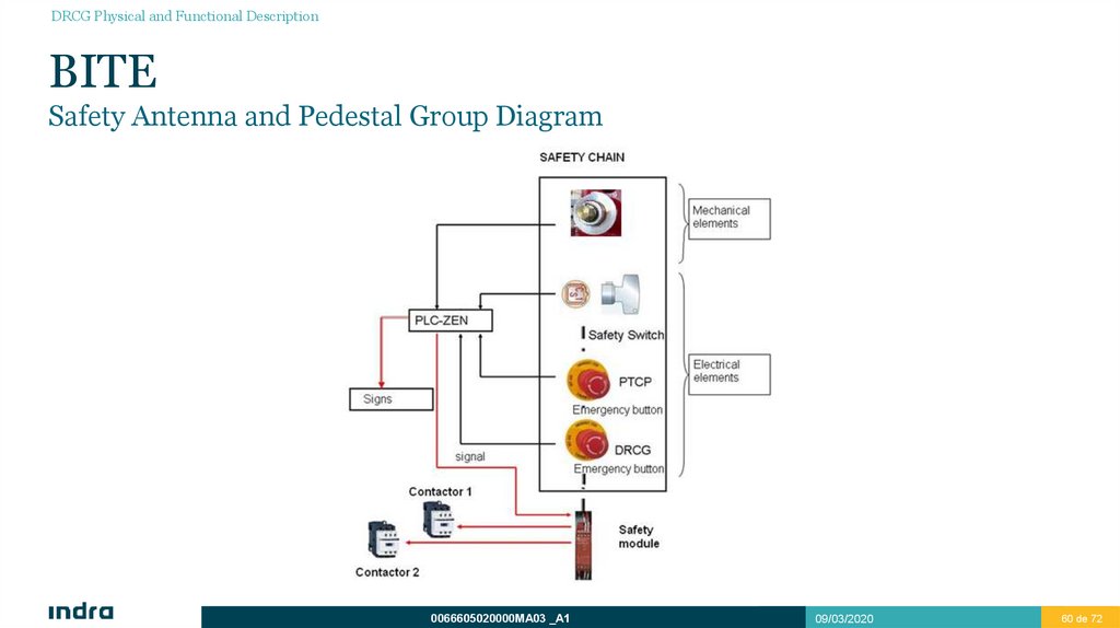
60.
DRCG Physical and Functional DescriptionBITE
Safety Antenna and Pedestal Group Diagram
0066605020000MA03 _A1
09/03/2020
60 de 72
60
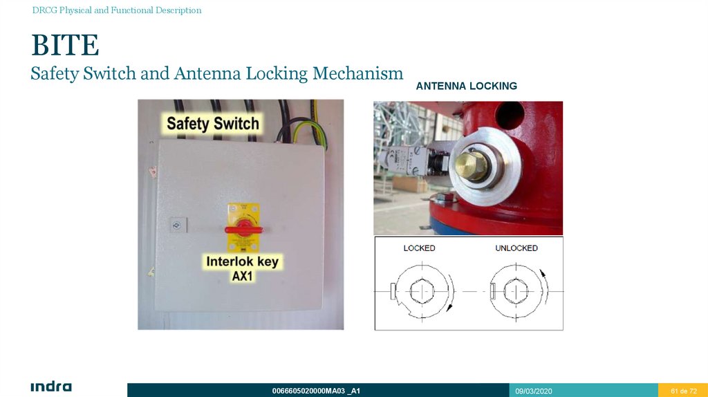
61.
DRCG Physical and Functional DescriptionBITE
Safety Switch and Antenna Locking Mechanism
0066605020000MA03 _A1
ANTENNA LOCKING
09/03/2020
61 de 72
61
62.
DRCG Physical and Functional DescriptionOperation
Pedestal Control Panel performs the following operations:
Antenna turning by means of motors control. It is possible to operate only with one motor.
Possibility of cutting energy off by means of emergency buttons.
Various independent control modes:
REMOTE: Control from CMS.
LOCAL: Control from DRCG frontal panel.
MAINTENANCE: Remove the key to use the PTCP.
Monitors their own devices and also controls equipment status.
Each electric line from the radar, either 400 Vac three-phase/230Vac single phase alternate current or 24/28 Vdc direct current, is
protected.
The system supplies energy to some antenna devices such as encoders, heaters and obstruction lights.
0066605020000MA03 _A1
09/03/2020
62 de 72
62
63.
DRCG Physical and Functional DescriptionOperation
Master-Slave
Two frequency controllers: ABB ACS-800 three phases, AC, 7,5Kw.
Convert alternate current into direct current, to change again late into alternate but with different frequency.
Both motors start using an acceleration ramp and stop by inertia in order not to damage transmission.
Master-Slave.
Used to distribute the wear of both motors and improve the operation in case of adverse weather conditions (torque control).
First controller which receive the start command is the master.
Master establishes the speed of the set and transmits to the second one the torque indication to keep same torque in both.
0066605020000MA03 _A1
09/03/2020
63 de 72
63
64.
DRCG Physical and Functional DescriptionOperation
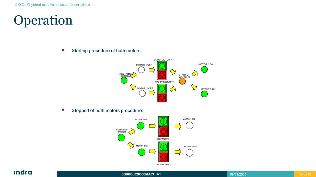
Starting procedure of both motors:
START MOTOR 1
MOTOR 1 ON
MOTOR 1 OFF
RESTARTED
SYSTEM
START UP
WARNING
START MOTOR 2
MOTOR 2 OFF
MOTOR 2 ON
Stopped of both motors procedure:
MOTOR 1 OFF
MOTOR 1 ON
RESTARTED
SYSTEM
STOP MOTOR 1
MOTOR 2 ON
MOTOR 2 OFF
STOP MOTOR 2
0066605020000MA03 _A1
09/03/2020
64 de 72
64
65.
DRCG Physical and Functional DescriptionPedestal Top Control Panel (PTCP)
Operation
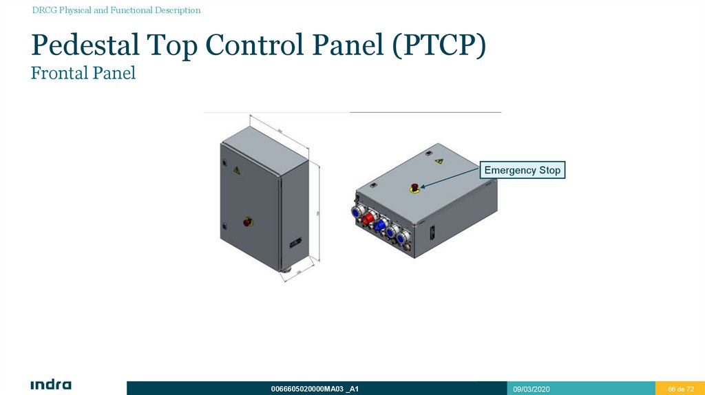
PTCP (Pedestal Top Control Panel) is a control panel located in the motor room where pedestal is installed.
Features:
PTCP – DRCG connection is complete. However, simultaneous controlling using both units is incompatible
with safety Independently controlled.
PTCP is a reduced version of the DRCG for maintenance purposes.
0066605020000MA03 _A1
09/03/2020
65 de 72
65
66.
DRCG Physical and Functional DescriptionPedestal Top Control Panel (PTCP)
Frontal Panel
Emergency Stop
0066605020000MA03 _A1
09/03/2020
66 de 72
66
67.
DRCG Physical and Functional DescriptionDRCG PHYSICAL AND FUNCTIONAL DESCRIPTION
Pedestal Top Control Panel (PTCP)
Features
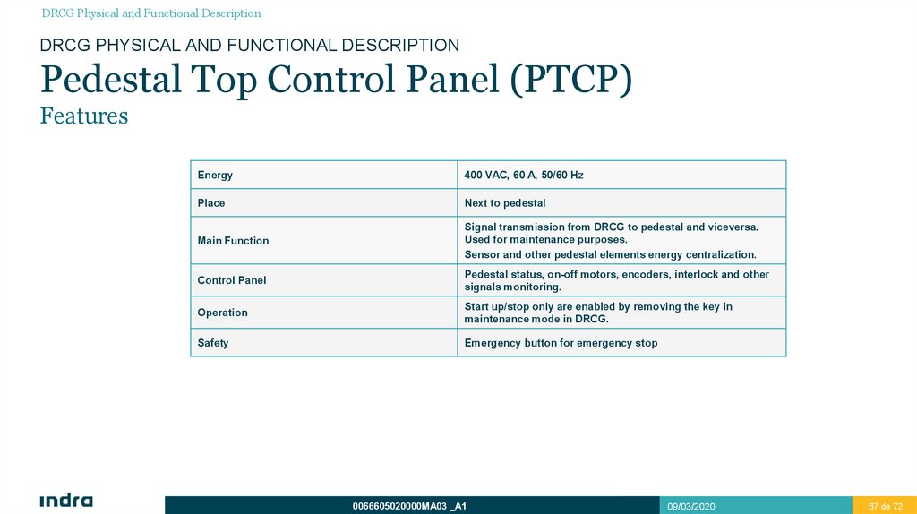
Energy
400 VAC, 60 A, 50/60 Hz
Place
Next to pedestal
Main Function
Signal transmission from DRCG to pedestal and viceversa.
Used for maintenance purposes.
Sensor and other pedestal elements energy centralization.
Control Panel
Pedestal status, on-off motors, encoders, interlock and other
signals monitoring.
Operation
Start up/stop only are enabled by removing the key in
maintenance mode in DRCG.
Safety
Emergency button for emergency stop
0066605020000MA03 _A1
09/03/2020
67 de 72
67
68.
DRCG Physical and Functional DescriptionJunction Box
Features
Internally is composed of interconnection terminals and a thermostat with a temperature probe that allows the activation of the
heaters when outside temperature is below 10ºC.
0066605020000MA03 _A1
09/03/2020
68 de 72
68
69.
APG Interfaces4
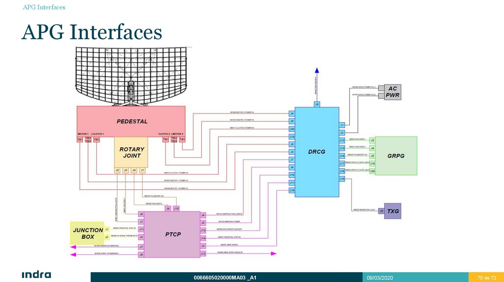
70.
APG InterfacesAPG Interfaces
0066605020000MA03 _A1
09/03/2020
70 de 72
70
71.
APG InterfacesAPG Interfaces
0066605020000MA03 _A1
09/03/2020
71 de 72
71