


 physics
 mechanics
Similar presentations:


Godfrin Cryocoolers
1.
Cryocourse 2016School and Workshop in Cryogenics and Quantum Engineering
26th September - 3rd October 2016
Aalto University, Espoo, Finland
Cryocoolers
Henri GODFRIN and Fons de Waele
CNRS/IN/MCBT – Grenoble
2.
The course is based on:Basic operation of cryocoolers and related thermal machines
A.T.A.M. de Waele
J. of Low Temp. Physics, Vol.164, pp.179-236 (2011) (open access)
Cryocoolers
A.T.A.M. de Waele
Lectures given at Cryocourse 2013 and former ones
Cryocoolers: the state of the art and recent developments
R. Radebaugh, J. Phys., Condens. Matter 21, 164219 (2009)
Documents from manufacturer’s Web pages:
Cryomech
http://www.cryomech.com
Sumitomo
http://www.shicryogenics.com/
Thales Cryogenics
http://www.thales-cryogenics.com
Advanced Research Systems http://www.arscryo.com/
Wikipedia: https://en.wikipedia.org/wiki/Cryocooler
3.
Outline of the course• Introduction
• Some thermodynamics
• Joule-Thomson coolers
• Stirling cycle
• Stirling engines
• Stirling coolers
• Pulse-tube coolers
• History
• Principles
• Commercial coolers and Applications
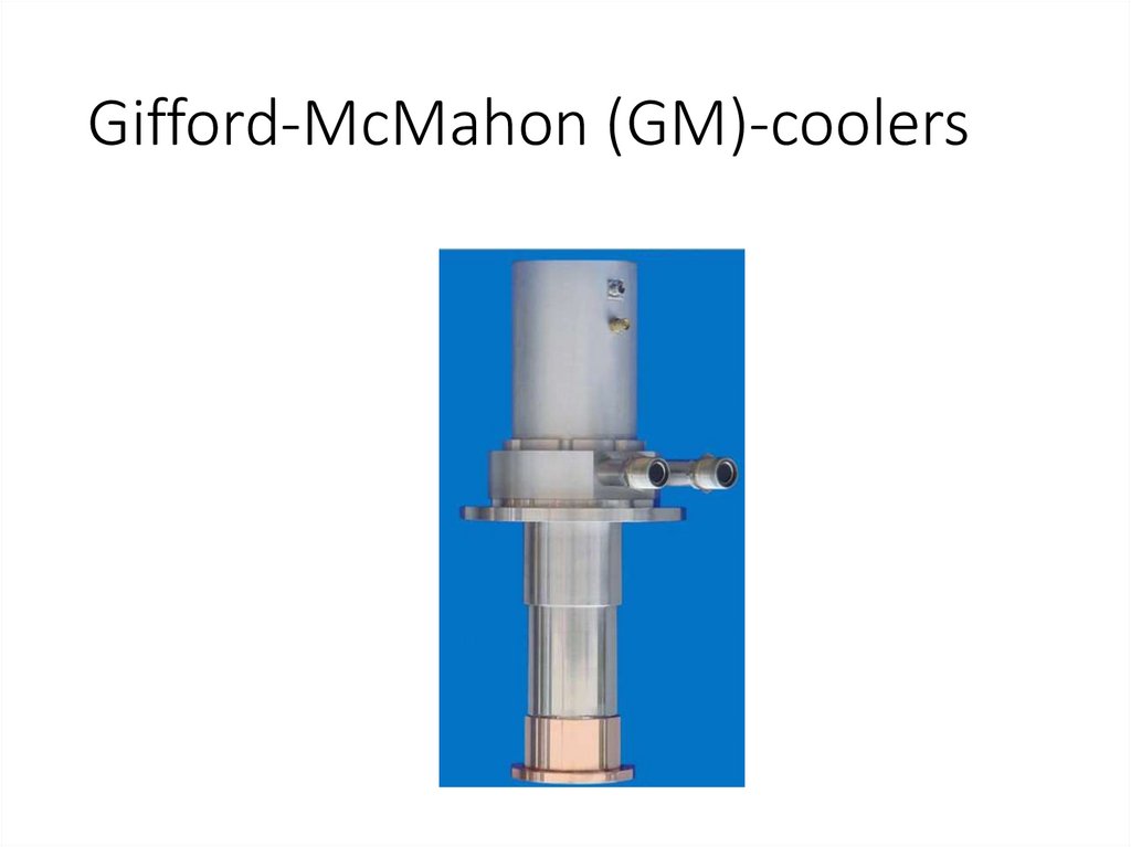
• Gifford-McMahon (GM)-coolers
4.
What is a « cryo-cooler »Cryocooler
From Wikipedia, the free encyclopedia
A Cryocooler is a standalone cooler, usually of
table-top size. It is used to cool some particular
application to cryogenic temperatures.
A recent review is given by Radebaugh.[1]
The present article deals with various types of
cryocoolers and is partly based on a paper by
de Waele.[2]
The name « cryocooler », however, is normally used to designate cyclic thermal
machines based on periodic flow of gases, operated in the refrigeration mode.
5.
Laws of Thermodynamics6.
Open systems7.
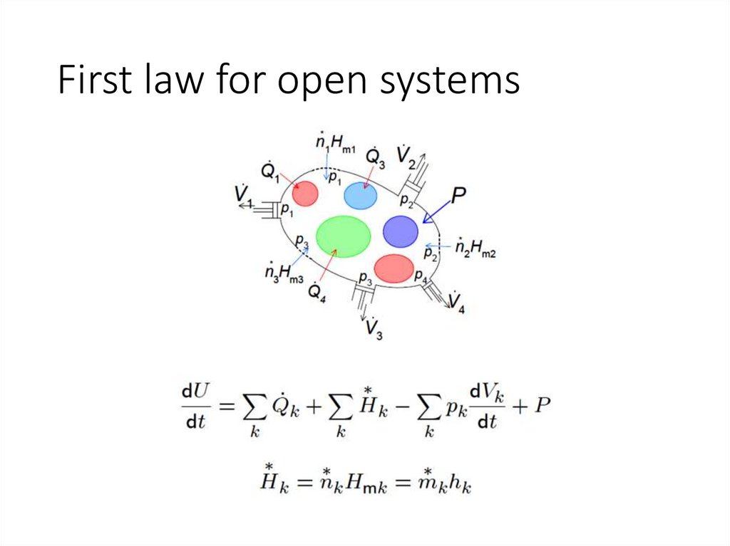
First law for open systems8.
second law for open systems9.
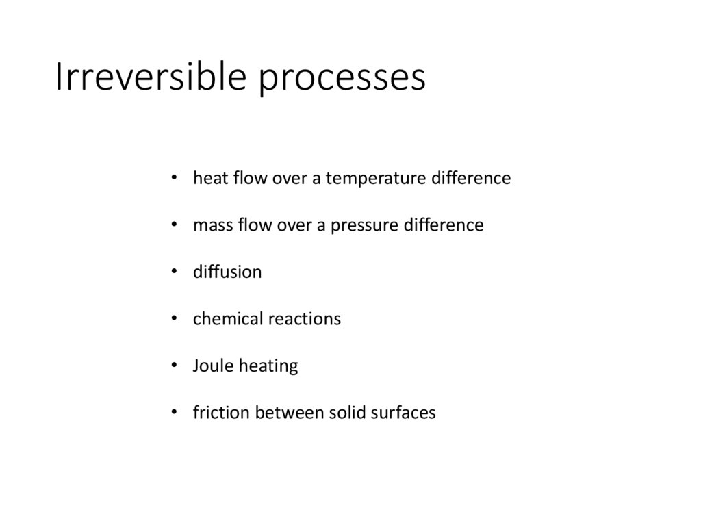
Irreversible processes• heat flow over a temperature difference
• mass flow over a pressure difference
• diffusion
• chemical reactions
• Joule heating
• friction between solid surfaces
10.
Heat enginesfirst law
reduces to
second law
reduces to
11.
Cold source needed….12.
Efficiency13.
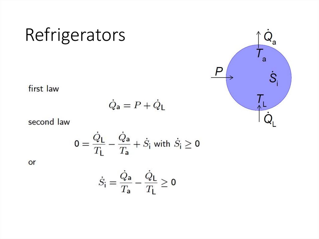
Refrigerators14.
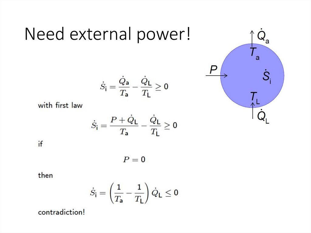
Need external power!15.
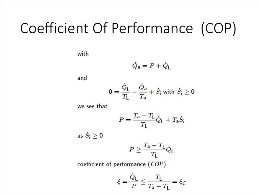
Coefficient Of Performance (COP)16.
Dissipated power17.
Different types of Cryo-coolersOscillating gas flow cryocoolers
• Stirling refrigerators
• Gifford-McMahon (GM) refrigerators
• Pulse-tube refrigerators
Constant gas flow cryocoolers
• Joule-Thomson cooler
• Dilution refrigerators (yes, some of them are table-top…;-)
18.
Joule-Thomson coolersInvented by Carl von Linde and William Hampson, it is
sometimes named after them.
Basically it is a very simple type of cooler which is widely
applied as the (final stage) of liquefaction machines.
It can easily be miniaturized, but it is also used on a very
large scale in the liquefaction of natural gas.
19.
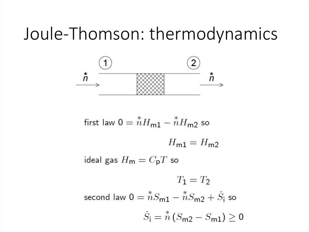
Joule-Thomson: thermodynamics20.
21.
Joule-Thomson coolerSchematic diagram of a JT liquefier
At the liquid side a fraction x of the
compressed gas is removed as liquid.
At room temperature it is supplied, so
that the system is in the steady state.
The symbols a…f refer to points in the
Ts - diagram.
(case of a nitrogen liquefier)
22.
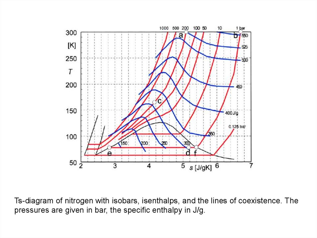
Ts-diagram of nitrogen with isobars, isenthalps, and the lines of coexistence. Thepressures are given in bar, the specific enthalpy in J/g.
23.
Ts-diagram of nitrogen with isobars at 1 and200 bar, the coexistence line and the
isenthalp of the JT-expansion indicated.
24.
Stirling cycle25.
Stirling cycle and Stirling engines26.
Stirling alpha enginehttps://en.wikipedia.org/wiki/Stirling_engine
27.
Stirling beta enginehttps://en.wikipedia.org/wiki/Stirling_engine
https://en.wikipedia.org/wiki/Stirling_engine
28.
Stirling CoolersThe thermal contact with the surroundings at the temperatures
Ta and TL is supposed to be perfect so that the compression and
expansion are isothermal
https://en.wikipedia.org/wiki/File:Schematic_Stirling_Cooler.jpg
29.
Stirling Coolers1. From a to b. The warm piston moves to the right over a certain distance
while the position of the cold piston is fixed. The compression at the hot end
is isothermal by definition, so a certain amount of heat Qa is given off to the
surroundings at temperature Ta.
2. From b to c. Both pistons move to the right so that the volume between
the two pistons remains constant. The gas enters the regenerator at the left
with temperature Ta and leaves it at the right with temperature TL. During
this part of the cycle heat is given off by the gas to the regenerator material.
During this process the pressure drops and heat has to be supplied to the
compression and expansion spaces to keep the temperatures constant.
3. From c to d. The cold piston moves to the right while the position of the
warm piston is fixed. The expansion is isothermal so heat QL is taken up
from the application.
4. From d to a. Both pistons move to the left so that the total volume
remains constant. The gas enters the regenerator at the right with
temperature TL and leaves it at the left with Ta so heat is taken up from the
regenerator material. During this process the pressure increases and heat
has to be extracted from the compression and expansion spaces to keep the
temperatures constant. In the end of this step the state of the cooler is the
same as at the start.
30.
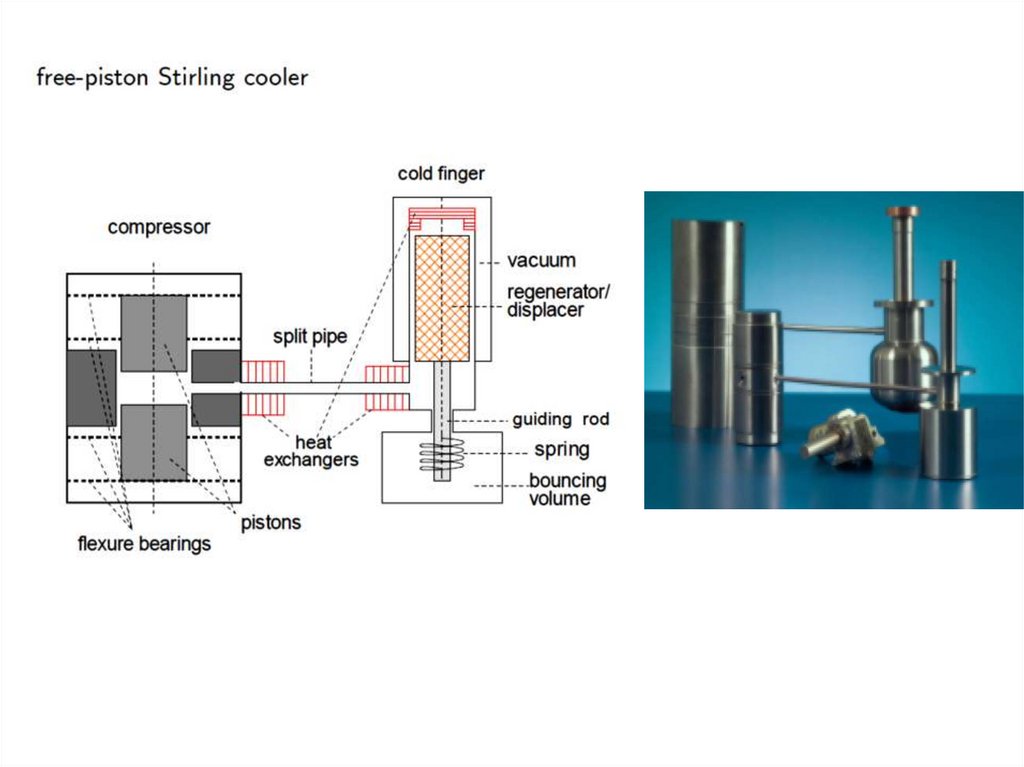
Stirling cooler31.
32.
Displacer-type Stirling coolersModified Stirling cycle. The cold piston is replaced by a displacer.
33.
PULSE-TUBE REFRIGERATORS(PTRs)
34.
Stirling type single-orifice PTRFrom left to right the system consists of a compressor with moving piston (piston), the after
cooler (X1), a regenerator, a low-temperature heat exchanger (X2), a tube (tube), a second
room-temperature heat exchanger (X3), an orifice (O), and a buffer.
The cooling power is generated at the low temperature TL. Room temperature is TH.
In this Section all flow resistances are neglected except from the orifice.
The system is filled with helium at an average pressure of typically 20 bar.
The part in-between the heat exchangers X1 and X3 is below room temperature.
It is contained in a vacuum chamber for thermal isolation.
35.
Some remarks…The piston moves the gas back and forth and generates a varying pressure in the
system. The pressure varies smoothly.
The operating frequency typically is 1 to 50 Hz.
Acoustic effects, such as travelling pressure waves, or fast pressure changes
(pulses), are absent.
The operation of PTR's has nothing to do with "pulses“… Wrong name!!!!
In the regenerator and in heat exchangers the gas is in good thermal contact with its
surroundings while in the tube the gas is thermally isolated.
36.
Thermodynamics…Gas elements inside the tube are compressed or expanded adiabatically and
reversibly, so their entropy is constant.
Using the expression for the molar entropy Sm of the gas
with T the temperature, Cp the molar heat capacity at constant pressure,
aV the volumetric thermal expansion coefficient given by
Vm the molar volume, and p the pressure. From Eq.(1), with dSm = 0, we see that
the temperature variation dT is related to a pressure variation dp according to
Usually aV > 0. This well-known fact means that compression leads to heating and
expansion to cooling. This fact is the basis for the operation of many types of coolers.
37.
Temperature-position curves of two gas elements (one at the cold end and one at the hot end)Left : a gas element enters the tube at temperature TL and leaves it at a lower temperature hence producing cooling.
Right : a gas element enters the tube at temperature TH and leaves it at a higher temperature producing heating.
38.
At the hot end gas flows from the buffer via the orifice into the tube with a temperature TH if thepressure pt is below the pressure in the buffer pB (pt < pB ).
If pt = pB the gas at the hot end comes to a halt.
If pt > pB the gas moves to the hot end of the tube and through the heat exchanger X and the orifice
into the buffer.
So gas elements enters the tube if pt < pB and leaves the tube if pt > pB .
So the final pressure is larger than the initial pressure.
Consequently the gas leaves the tube with a temperature higher than the initial temperature TH .
Heat is released via the heat exchanger X3 to the surroundings and the gas flows to the orifice at
ambient temperature.
At the cold end of the tube the gas leaves the cold heat exchanger X and enters the tube when the
pressure is high and temperature TL. It returns to X when the pressure is low and the temperature is
below TL. Hence producing cooling.
The analysis of the situation at the cold end is a bit more complicated due to the fact that the velocity
at the cold end is determined by the velocity of the gas at the hot end and by the elasticity of the gas
column in the tube. Still the situation is basically the same.
39.
Ideal regeneratorsThe thermodynamic and hydrodynamic properties of regenerators usually are extremely complicated.
In many cases it is necessary to make simplifying assumptions.
The degree of idealization may differ from case to case.
In its most extreme form in an ideal regenerator:
1. the heat capacity of the matrix is much larger than of the gas;
2. the heat contact between the gas and the matrix is perfect;
3. the gas in the regenerator is an ideal gas;
4. the flow resistance of the matrix is zero;
5. the axial thermal conductivity is zero;
6. sometimes it is also assumed that the void volume of the matrix is zero.
Depending on the situation one or more assumptions may be dropped. Usually it is replaced by another
assumption with a less rigorous nature.
If conditions 1 and 2 are satisfied then the gas temperature at a certain point in the regenerator is constant.
If, in addition, condition 3 is satisfied as well then the average enthalpy flow in the regenerator is zero.
If conditions 2, 4,and 5 are satisfied there are no irreversible processes in the regenerator.
40.
Regenerator: materialsGdAlO3
41.
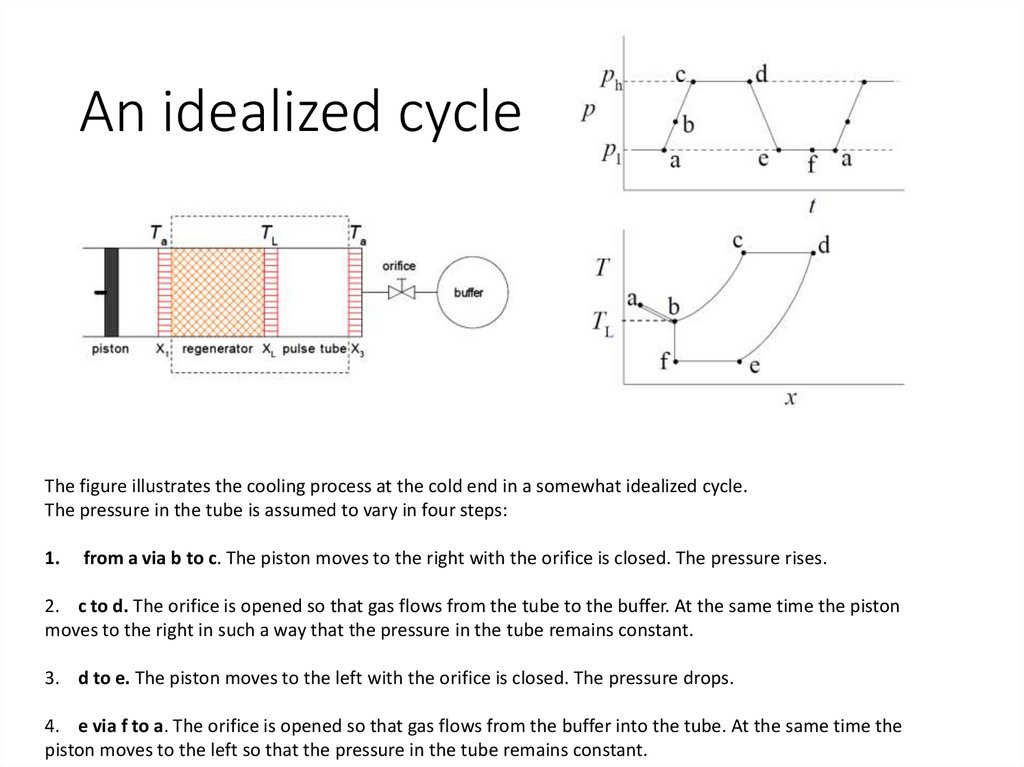
An idealized cycleThe figure illustrates the cooling process at the cold end in a somewhat idealized cycle.
The pressure in the tube is assumed to vary in four steps:
1.
from a via b to c. The piston moves to the right with the orifice is closed. The pressure rises.
2. c to d. The orifice is opened so that gas flows from the tube to the buffer. At the same time the piston
moves to the right in such a way that the pressure in the tube remains constant.
3. d to e. The piston moves to the left with the orifice is closed. The pressure drops.
4. e via f to a. The orifice is opened so that gas flows from the buffer into the tube. At the same time the
piston moves to the left so that the pressure in the tube remains constant.
42.
Now we follow a gas element that is inside the regeneratorat the start of the cycle (point (a)).
a to b: When the pressure rises the gas element moves to the
right but its temperature remains at the local temperature due to
the good heat contact with the regenerator material.
At point (b) our gas element leaves the regenerator and X2 and
enters the tube with the temperature TL of the heat exchanger
X2. The pressure is pb.
b to c: Now the gas element is thermally isolated and its
temperature rises together with the pressure
while it moves to the right.
c to d: The gas element moves to the right. The pressure is constant so the temperature is constant.
d to e: When the pressure drops the gas element moves to the left. As it is thermally isolated its
temperature drops to a value below TL since pe < pb:
e to f : The gas element moves to the left. The pressure is constant so the temperature is constant.
At point (f) the gas element enters the heat exchanger X2. In passing X2 the gas extracts heat
(produces cooling) from X2. The gas element warms up to the temperature TL.
f to a: The gas element is inside the regenerator and moves with the local temperature back to its
original position.
43.
Thermodynamics of PTR’sIdeal PTR: dissipation only occurs in the orifice
44.
Thermodynamics of PTR’sThermodynamic systems containing the orifice (a), the heat exchanger
X3 (b), the pulse tube and its heat exchangers (c), and the regenerator
and its heat exchangers (d)
45.
46.
Coefficient Of Performance (COP)47.
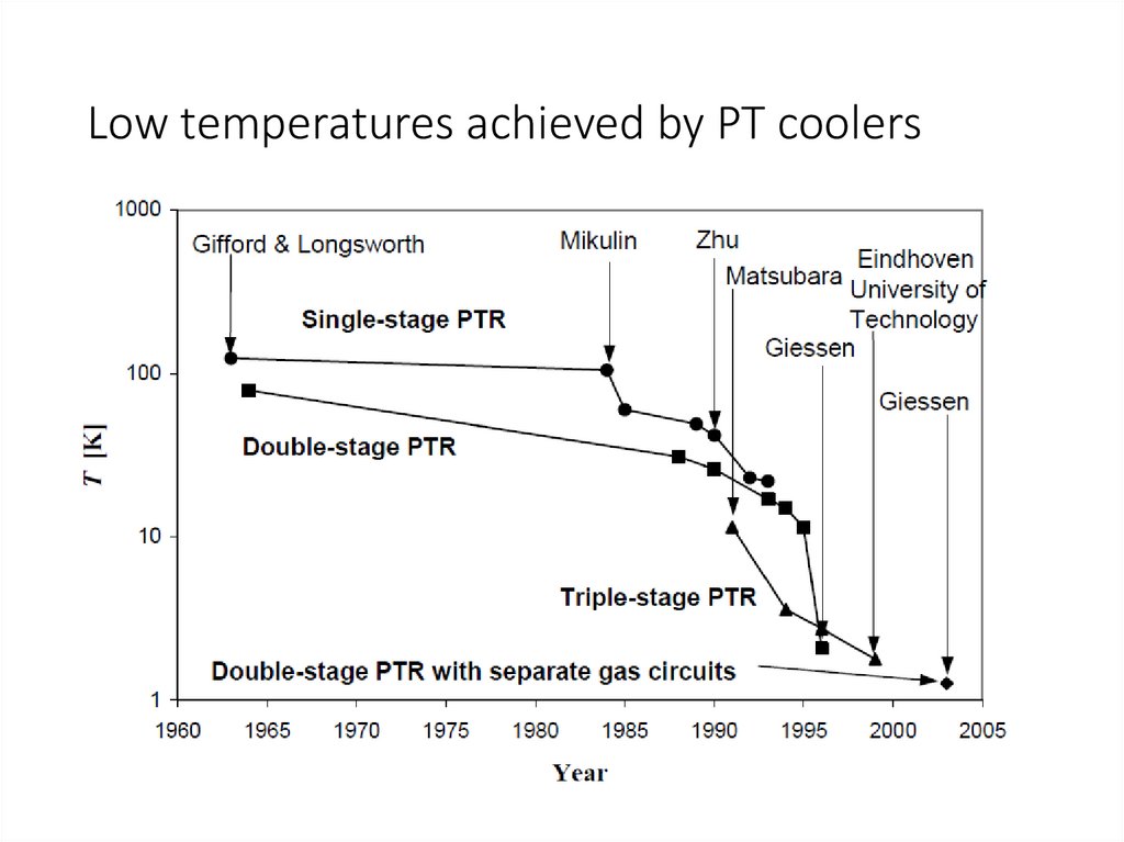
PULSE-TUBE REFRIGERATORS: first machinesPulse-tube refrigerators have their origin in an observation that W. E. Gifford made, while
working on the compressor in the late 1950’s. He noticed that a tube, which branched from
the high-pressure line and was closed by a valve, was hotter at the valve than at the
branch.
He recognized that there was a heat pumping mechanism that resulted from pressure
pulses in the line. In 1963 Gifford together with his research assistant R. C. Longsworth
introduced the Basic Pulse-Tube Refrigerator (BPTR).
The BPTR has not so much in common with the modern PTRs. The cooling principle of the
BPTR is the surface heat pumping, which is based on the exchange of heat between the
working gas and the pulse tube walls.
The lowest temperature, reached by Gifford and Longsworth was 124 K with a single-stage
PTR and 79 K with a two-stage PTR.
48.
The PTR has no moving parts in the low-temperature region, and, therefore,has a long lifetime and low mechanical and magnetic interferences.
A typical average pressure in a PTR is 10 to 25 bar, and a typical pressure
amplitude is 2 to 7 bar.
A piston compressor (in case of a Stirling type PTR) or a combination of a
compressor and a set of switching valves (GM type PTR) are used to create
pressure oscillations in a PTR.
49.
The main breakthrough came in 1984, when Mikulin and his co-workers invented the Orifice PulseTube Refrigerator (OPTR) [6]. A flow resistance, the orifice, was inserted at the warm end of the
pulse tube to allow some gas to pass to a large reservoir. With a single-stage configuration of the
OPTR Mikulin achieved a low temperature of 105 K, using air as the working gas.
Soon afterwards R.Radebaugh reached 60 K with a similar device, using helium [7]. For the first
time since the invention of the PTR its performance became comparable to the Stirling cooler.
In 1990 Zhu et al. connected the warm end of the pulse tube with the main gas inlet by a tube,
containing a second orifice [8]. Thus, a part of the gas could enter the pulse tube from the warm
end, by-passing the regenerator. Because of this effect such a configuration of the PTR was called
the Double-Inlet Pulse-Tube Refrigerator (DPTR).
In 1994 Y. Matsubara used this configuration to reach a temperature as low as 3.6 K with a threestage PTR [9].
In 1999 with a three stage DPTR a temperature of 1.78 K was reached at the Low Temperature
Group of Eindhoven University of Technology [10].
In 2003 the group of Prof. G. Thummes from Giessen University developed a double-circuit
3He/4He PTR that achieved 1.27 K [11].
Adapted from: PhD Thesis
Low-temperature cryocooling / by Irina Tanaeva. Eindhoven : Technische Universiteit Eindhoven, 2004. –
ISBN 90-386-2005-5
50.
REFERENCES1. McClintock, P. V. E., Meredith, D. J., Wigmore, J. K., “Matter at low temperatures”,
John Wiley & Sons, New York, 1984.
2. Good, J., Hodgson, S., Mitchell, R., and Hall, R., “Helium free magnets and research
systems”, Cryocoolers 12, 2003, pp. 813-816.
3. Walker, G., “Cryocoolers”, Plenum Press, New York and London, 1983.
4. Gifford, W.E. and Longsworth, R. C., “Pulse tube refrigeration”, Trans. ASME, 1964,
pp. 264-268.
5. Longsworth, R. C., “An experimental investigation of pulse tube refrigeration heat
pumping rates”, Advances in Cryogenic Engineering 12, 1967, pp. 608-618.
6. Mikulin, E.I., Tarasov, A.A., and Shkrebyonock, M., P., “Low-temperature expansion
pulse tubes”, Advances in Cryogenic Engineering 29, 1984, pp. 629-637.
7. Radebaugh, R., Zimmerman, J., Smith, D., R., and Louie, B., “Comparison of three
types of pulse tube refrigerators: New methods for reaching 60 K”, Advances in
Cryogenic Engineering 31, 1986, pp. 779-789.
8. Zhu, Sh., Wu, P., and Chen, Zh., “Double inlet pulse tube refrigerators: an important
improvement”, Cryogenics 30, 1990, pp. 514-520.
9. Matsubara, Y. and Gao, J., L., “Novel configuration of three-stage pulse tube
refrigerator for temperatures below 4 K”, Cryogenics 34, 1994, pp. 259-262.
10. Xu, M. Y., Waele, A. T. A. M. de, and Ju, Y. L., “A Pulse Tube Refrigerator Below 2
K”, Cryogenics 39, 1999, pp. 865-869.
11. Jiang, N., Lindemann, U., Giebeler, F., and Thummes, G., “A He pulse tube cooler
operating down to 1.27 K”, Cryogenics 44, 2004, pp. 809-816.
12. Zia, J. H., “Design and operation of a 4 kW liner motor driven pulse tube cryocooler”,
Advances in Cryogenic Engineering 49, 2004, pp. 1309-1317.
3
PhD Thesis
Low-temperature cryocooling / by Irina Tanaeva. Eindhoven : Technische Universiteit Eindhoven, 2004. –
ISBN 90-386-2005-5
51.
Low temperatures achieved by PT coolers52.
53.
54.
Additional cooling power[5] Experimental results on the free cooling power available on 4K pulse tube coolers
T. Prouvé, H. Godfrin, C. Gianèse, S. Triqueneaux, A. Ravex
J. of Phys. : Conference Series 150, 012038 (2009).
55.
Additional cooling powerSee article below for complete characterization of the cooling
power as a function of the heat applied to all exchangers:
Experimental results on the free cooling power available on 4K pulse tube coolers
T. Prouvé, H. Godfrin, C. Gianèse, S. Triqueneaux, A. Ravex
J. of Phys. : Conference Series 150, 012038 (2009).
56.
57.
Commercial pulse-tubes58.
Standard 4K Cryomech Single-Stage Pulse Tube CryorefrigeratorsAll models have remote-motor options available
PT 10
•12W @ 80K
•Air or Water Cooled
PT 60
•60W @ 80K
•Air or Water Cooled
PT 63
•23W @ 40K
•Air or Water Cooled
PT 90
•90W @ 80K
•Air or Water Cooled
59.
Standard 4K Cryomech Two-Stage Pulse Tube CryorefrigeratorsAll models have remote-motor options available
PT 403
First Stage 7W @ 65K
Second Stage 0.25W @ 4.2K
Air or Water Cooled
PT 405
First Stage 25W @ 65K
Second Stage 0.5W @ 4.2K
Air or Water Cooled
PT 407
First Stage 25W @ 55K
Second Stage 0.7W @ 4.2K
Air or Water Cooled
PT 415
First Stage 40W @ 45K
Second Stage 1.5W @ 4.2K
60.
PT 40561.
62.
63.
64.
Features of Pulse Tube Cryorefrigerators• Long mean time between maintenance
• Minimal general maintenance
• Ideal for vibration sensitive applications
• Directly liquefy helium gas and recondense boil-off in liquid cryostat
•Direct conductive cooling in dry cryostats (including low vibration options)
65.
Liquid Helium Plants and Recovery SystemsLiquefaction rates from 6-60 liters per day
66.
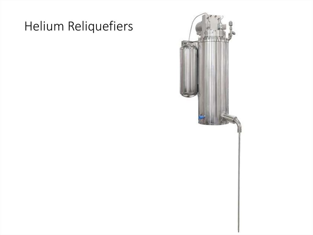
Helium Reliquefiers67.
Sumitomo pulse-tubesSpecifications
Cold Head Model
RP-062B
RP-062BS
RP-082B2
RP-082B2S
50 Hz
30 W @ 65 K
25 W @ 65 K
45 W @ 45 K
35 W @ 45 K
60 Hz
30 W @ 65 K
25 W @ 65 K
45 W @ 45 K
35 W @ 45 K
50 Hz
0.5 W @ 4.2 K
0.4 W @ 4.2 K
1.0 W @ 4.2 K
0.9 W @ 4.2 K
60 Hz
0.5 W @ 4.2 K
0.4 W @ 4.2 K
1.0 W @ 4.2 K
0.9 W @ 4.2 K
<3.0 K
<3.0 K
<3.0 K
50 Hz
<100
<100
<80
60 Hz
<90
<90
<80
23.2 kg
(51.2 lbs.)
23.5 kg
(51.8 lbs.)
26.0 kg
(57.3 lbs.)
1st Stage Capacity
2nd
Stage Capacity
Minimum Temperature1
Cooldown Time
Weight
<3.0 K
<90
<90
26.0 kg
(57.3 lbs.)
68.
RP-062B 4K Pulse Tube Cryocooler Serieshttp://www.shicryogenics.com/products/pulse-tube-cryocoolers/rp-062b-4k-pulse-tube-cryocooler-series/
69.
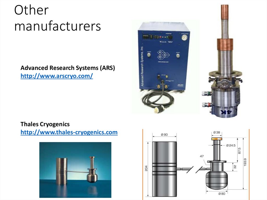
Othermanufacturers
Advanced Research Systems (ARS)
http://www.arscryo.com/
Thales Cryogenics
http://www.thales-cryogenics.com
70.
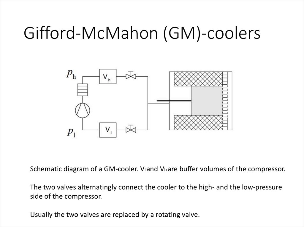
Gifford-McMahon (GM)-coolersSchematic diagram of a GM-cooler. Vl and Vh are buffer volumes of the compressor.
The two valves alternatingly connect the cooler to the high- and the low-pressure
side of the compressor.
Usually the two valves are replaced by a rotating valve.
71.
Gifford-McMahon (GM)-coolersIn reality rotary valves are used
72.
Gifford-McMahon (GM)-coolers73.
74.
75.
Fons’s wise wordsThe invisible cooler:
- no cost
- no maintenance
- no noise
- no vibrations
- no EM interference
- no space
- no weight
- no water, ice, ..
- no vacuum pump, cooling water,...
- no.... alternative