


 internet
Similar presentations:


Investigating OpenFlow negotiations. Lecture 6
1.
Lecture 6Investigating
OpenFlow
negotiations
1
2.
Objectives1. OFPT_HELLO message
2. Switch datapath IDs (DPIDs)
3. Packet_in message and Tablemiss flow entry
4. Tables and pipelines
5. Flow modifications (Flow mod)
2
3.
Introduction to the lectureIn this lecture, you will continue investigating OpenFlow
negotiation using Wireshark captures. You will compare the
captured packets with information contained in the
OpenFlow specification document.
You will
learn about:
Capture OpenFlow messages
Switch features
Switch datapath IDs (DPIDs)
Packet in messages
Buffering
Tables and pipelines
Flow modifications (Flow mod)
Error messages
3
4.
InvestigatingOpenFlow
negotiations
1. OFPT_HELLO
message
4
5.
Capture OpenFlow messagesIn this section, you will learn to use Wireshark to capture
OpenFlow messages sent between the HP VAN SDN Controller
and OpenFlow switches.
You will learn to capture initial OpenFlow messages and
compare the actual OpenFlow implementation in a network
with information contained in the OpenFlow specification
document. Figure below illustrates the IP addresses and
configuration these instructions use.
Comware switch C2 and ProVision switch P1 are configured to
communicate with HP VAN SDN Controller 192.168.56.11. You
will learn to capture OpenFlow messages using Wireshark on
the Jumphost (192.168.56.5).
5
6.
Capture OpenFlow messages6
7.
Capture OpenFlow messagesSee Table for additional IP addresses used in instructions for
this section.
If you have installed evaluation copies of HP VAN SDN
Controller, Mininet, and Network Protector on your PC so
that you could follow instructions in the previous Lectures,
you will need to disable Network Protector for the following
instruction set. Following are instructions for doing this.
7
8.
Capture OpenFlow messages1. Disable Network Protector on the HP VAN SDN Controller. Browse to
https://<controller IP address>/sdn/ui and click Applications. If Network
Protector is active, select the application and click Disable to disable it
(see Figure).
8
9.
Capture OpenFlow messagesFigure illustrates the relationship between the controller and an
OpenFlow switch.
As quoted earlier in this chapter: “An
OpenFlow Switch consists of one or more
flow tables and a group table, which perform
packet lookups and forwarding, and an
OpenFlow channel to an external controller.
The switch communicates with the controller
and the controller manages the switch via the
OpenFlow protocol.”
Earlier in this chapter, you also learned that
the OpenFlow protocol supports three
message types. The OpenFlow protocol
supports three message types: controller-toswitch, asynchronous, and symmetric.
9
10.
Capture OpenFlow messagesOpenFlow will be disabled and then re-enabled so you can
view the OpenFlow channel negotiation between the switch
and the HP VAN SDN Controller. An OpenFlow channel is
the TCP or TLS session between the switch and the
controller used for sending and receiving OpenFlow
messages.
Initial OpenFlow
messages we will
capture and view
in Wireshark
include:
Switch to Controller = Hello
Controller to Switch = Hello
Controller to Switch = Features request
Switch to Controller = Features reply
Controller to Switch = Set config
Switch to Controller = Error
10
11.
Capture OpenFlow messages2. Disable OpenFlow on Comware 2 (C2):
3. Disable OpenFlow on
ProVision 1 (P1):
4. Disable OpenFlow on
ProVision 2 (P2):
11
12.
Capture OpenFlow messages9. Specify the following filter: openflow_v4 and click Apply.
See Figure. This filter will display OpenFlow 1.3 packets:
Result: At the moment no OpenFlow packets are seen because
OpenFlow is disabled on the switches.
12
13.
Capture OpenFlow messages10. Enable OpenFlow on Comware 2 (C2):
11. Stop the Wireshark capture (see Figure).
13
14.
Capture OpenFlow messages12. Find the OFPT_HELLO message (first OpenFlow message)
(check Figure). Which version of OpenFlow is the hello message?
Answer: The version of OpenFlow is 1.3 (0x04).
14
15.
Capture OpenFlow messages13. This first OpenFlow message is a Hello message. Is this a controllerto-switch, asynchronous, or symmetric message type? Check Figure.
Answer: This message is a Hello message with code = 0. There are other
OpenFlow messages listed below and which we will discuss. This is a
symmetric message.
15
16.
Message typesThe following extract from the OpenFlow specification provides
more detail of message types: The length field indicates the total
length of the message, so no additional framing is used to distinguish
one frame from the next. The type can have the following values:
16
17.
Message types17
18.
Message types18
19.
OpenFlow specification14. Which device initiated the connection? Check Figure.
Answer: The Comware switch C2 (10.1.1.252) sent this message. In
other words, the switch initiated the connection to the controller.
19
20.
OpenFlow specification15. Can a routed, non-OpenFlow, transit network be used for
the OpenFlow channel between the switch and the controller?
Answer: A non-OpenFlow, routed network can be used as the
transit network for the OpenFlow Channel between the switch
and the controller. Comware switch C1 is not running
OpenFlow and is routing traffic from VLAN 1 to VLAN 192.
16. Optional: Watch the following video explaining how HP
configured a network for Interop. In this example the HP VAN
SDN Controller was on one coast of the USA and the
OpenFlow switches were on the other coast of the USA.
20
21.
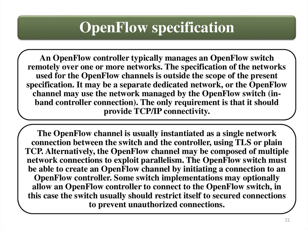
OpenFlow specificationAn OpenFlow controller typically manages an OpenFlow switch
remotely over one or more networks. The specification of the networks
used for the OpenFlow channels is outside the scope of the present
specification. It may be a separate dedicated network, or the OpenFlow
channel may use the network managed by the OpenFlow switch (inband controller connection). The only requirement is that it should
provide TCP/IP connectivity.
The OpenFlow channel is usually instantiated as a single network
connection between the switch and the controller, using TLS or plain
TCP. Alternatively, the OpenFlow channel may be composed of multiple
network connections to exploit parallelism. The OpenFlow switch must
be able to create an OpenFlow channel by initiating a connection to an
OpenFlow controller. Some switch implementations may optionally
allow an OpenFlow controller to connect to the OpenFlow switch, in
this case the switch usually should restrict itself to secured connections
to prevent unauthorized connections.
21
22.
OpenFlow specification17. Which Layer 4 protocol is used? Check Figure.
Answer: TCP was used for this connection.
22
23.
OpenFlow specification18. How did the switch learn the HP VAN SDN Controller IP address?
Answer: The switch was manually configured with the IP address of the
controller with the following command: controller 1 address ip
192.168.56.11. OpenFlow controllers are not automatically or
dynamically discovered by switches.
The switch must be able to establish communication with a controller
at a user-configurable (but otherwise fixed) IP address, using either a
user-specified transport port or the default transport port. If the switch
is configured with the IP address of the controller to connect to, the
switch initiates a standard TLS or TCP connection to the controller.
Traffic to and from the OpenFlow channel is not run through the
OpenFlow pipeline. Therefore, the switch must identify incoming
traffic as local before checking it against the flow tables.
23
24.
OpenFlow specification19. View the Hello message sent by the controller to the switch
(next message) (see Figure).
Result: This Hello message also has a version of 1.3.
24
25.
OpenFlow specification20. When a switch supports OpenFlow 1.0 and 1.3, what is the version
field set to when communicating with the controller (see Figure)?
Answer: The switch will inform the controller of its highest
supported version (1.3 in this example).
25
26.
OpenFlow specification21. How is the version of OpenFlow used between the switch and the controller
determined?
Answers: The switch and controller negotiate to use the highest supported
version of OpenFlow.
22. What does the OFNET_VERSIONBITMAP determine? (see Figure).
Answer: The OFNET_VERSIONBITMAP determines if the highest number or
lowest number is used.
26
27.
OFPT_HELLO messageWhen an OpenFlow connection is first established, each side of
the connection must immediately send an OFPT_HELLO
message with the version field set to the highest OpenFlow
protocol version supported by the sender. This Hello message
may optionally include some OpenFlow elements to help
connection setup.
Upon receipt of this message, the recipient must calculate the
OpenFlow protocol version to be used. If both the Hello message
sent and the Hello message received contained a
OFPHET_VERSIONBITMAP hello element, and if those
bitmaps have some common bits set, the negotiated version must
be the highest version set in both bitmaps. Otherwise, the
negotiated version must be the smaller of the version number
that was sent and the one that was received in the version fields.
27
28.
InvestigatingOpenFlow
negotiations
2. Switch datapath IDs
(DPIDs)
28
29.
Network topologyInstructions
for this
section will
use the IP
addresses
and
network
topology in
Figure.
29
30.
Configure Comware switch1. Disable OpenFlow on Comware 2 (C2):
In later releases of the Comware operating system,
the command undo active instance is supported.
30
31.
Configure Provision switch2. Configure ProVision 1 (P1) to use controller 192.168.56.11
(but do not enable the instance yet):
31
32.
Start Wireshark3. Start a new Wireshark capture, as illustrated in Figure.
32
33.
Enable OpenFlow switchs4. Enable OpenFlow on ProVision switch 1 (P1):
5. Enable OpenFlow on Comware switch 2 (C2):
33
34.
Clear the Address Resolution Protocol (ARP)6. Clear the Address Resolution Protocol (ARP) cache on UserVM3
(PC connected to ProVision Switch P1), as shown in Figure:
Start command prompt as
administrator
34
35.
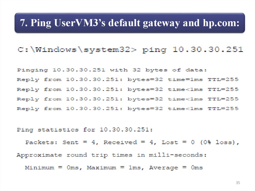
7. Ping UserVM3’s default gateway and hp.com:35
36.
7. Ping UserVM3’s default gateway and hp.com:36
37.
Stop Wireshark8. Stop the Wireshark capture, as illustrated in Figure.
9. Which device determines the switch DPID (controller or switch)?
Specify the following Wireshark filter and click Apply:
openflow_v4.switch_features.capabilities
Answer: The switch determines its own DPID.
37
38.
Features Reply messageSelect the Features Reply message from 10.1.1.253 in the
Wireshark capture, as illustrated in Figure.
38
39.
Features Reply messageSelect the Features Reply message from 10.1.1.252 in the
Wireshark capture, as illustrated in Figure.
39
40.
OpenFlow specificationThe datapath_id field uniquely identifies a
datapath. The lower 48 bits are intended
for the switch MAC address, while the top
16 bits are up to the implementer. An
example use of the top 16 bits would be a
VLAN ID to distinguish multiple virtual
switch instances on a single physical
switch. This field should be treated as an
opaque bit string by controllers.
40
41.
ProVision switch DPIDs calculation10. How are ProVision switch DPIDs
calculated?
Answer:
ProVision
switches
• The most significant 16 bits are the VLAN
number associated with the OpenFlow
instance. So for the OpenFlow instance
configured on VLAN 30, this number will
be “1E”. (30 in decimal equates to 1E in
hexadecimal). Hence the switches are
identified by 00:1E.
• Least significant 48 bits are the switch
MAC address.
41
42.
OpenFlow MonitorFigure shows ProVision switch 2 (P2) in our example topology with instance 30:
Figure shows an example of a 5406zl switch configured with instance 11.
42
43.
Comware switch DPIDs calculation11. How are Comware switch DPIDs calculated?
DPIDs on
Comware
switches:
• Comprised of the instance ID and the bridge
MAC address. The most significant 16 bits
are the instance ID.
• The least significant 48 bits are the bridge
MAC address.
Figure shows a 5920 switch configured with instance 1:
43
44.
Open vSwitch DPIDs calculationHow are Open vSwitch DPIDs calculated?
Open vSwitch
switch DPIDs:
• Comprised of 00:00 and the MAC
address of the OVS bridge.
Figure shows OVS running KVM.
44
45.
InvestigatingOpenFlow
negotiations
3. Packet_in message and
Table-miss flow entry
45
46.
Packet_in message12. What is a packet_in message?
Specify the following filter and click Apply:
In the
Wireshark
capture in
Figure, a
packet_in
message is
displayed. This
is an ARP
message that is
encapsulated
in OpenFlow
and forwarded
to the
controller for
processing.
46
47.
Packet_in message13. Why was this packet sent to the controller? Check Figure.
Answer: The
reason given
for
forwarding
the packet to
the controller
is:
OFPR_ACTION (1)
which means
this was
explicitly
programmed
to forward
traffic to the
controller.
47
48.
Packet_in messageThe OpenFlow specification provides the following detail:
The reason field can be any of these values:
48
49.
Packet_in messageThis matches the flow entry programmed by the controller. To see this, click
OpenFlow Monitor in the HP VAN SDN Controller GUI, as illustrated in Figure.
49
50.
Packet_in messageSelect ProVision Switch 1 (10.1.1.253) and select Flows (see Figure).
Find the ARP entry in table 100 and then expand the flow entry.
Result: The controller is copying ARP messages
so that it can discover hosts on the network.
50
51.
Table-miss flow entry14. Which entry is the tablemiss flow entry in an
OpenFlow table?
Answer: The table-miss
flow entry for table 100 is
shown in Figure.
15. What priority does a
table miss have? What does
it match on?
Answer: The table-miss
flow entry has a priority of
0 and a blank match field.
Find the table-miss flow entry in Table 100 (table 100, priority 0,
match field = blank). Expand the flow entry as shown in Figure.
Result: The table-miss entry will output traffic that does not match
any other flow entries in the flow table to the NORMAL port.
51
52.
Table-miss flow entryEvery flow table must support a table-miss flow entry to process table misses.
The table-miss flow entry specifies how to process packets unmatched by other
flow entries in the flow table, and may, for example, send packets to the
controller, drop packets or direct packets to a subsequent table.
View the table-miss entry on Comware C2, as shown in Figure.
52
53.
Table-miss flow entryThe table-miss flow entry is identified by its match and its priority, it
wildcards all match fields (all fields omitted) and has the lowest
priority (0).
The match of the table-miss flow entry may fall outside the normal
range of matches supported by a flow table, for example, an exact
match table would not support wildcards for other flow entries but
must support the table-miss flow entry wildcarding all fields.
The table-miss flow entry may not have the same capability as
regular flow entry. The table-miss flow entry must support at least
sending packets to the controller using the CONTROLLER reserved
port and dropping packets using the Clear-Actions instruction.
Implementations are encouraged to support directing packets to a
subsequent table when possible for compatibility with earlier
versions of this specification.
53
54.
Table-miss flow entry16. View the Flow tables of ProVision Switch P1 in Figure. Why does the
ProVision switch have multiple entries with a priority of zero?
Answer: Each table has a table-miss entry. There are three tables in the
ProVision switch output (Table 0, Table 100, and Table 200). Each table as a
separate table-miss entry and according action.
54
55.
Table-miss flow entry17. Is a table-miss entry required?
Answer: The table-miss flow entry behaves in most ways
like any other flow entry: it does not exist by default in a
flow table, the controller may add it or remove it at any
time, and it may expire.
18. What happens if there is no table-miss entry?
Answer: If the table-miss flow entry does not exist, by
default packets unmatched by flow entries are dropped
(discarded). A switch configuration, for example, using
the OpenFlow Configuration Protocol, may override this
default and specify another behavior.
55
56.
InvestigatingOpenFlow
negotiations
4. Tables and pipelines
56
57.
OpenFlow tables19. How many OpenFlow tables must a compliant OpenFlow
switch have?
Answer: An OpenFlow switch must have at least one OpenFlow
table.
20. What is the maximum number of OpenFlow tables a switch
may have?
Answer: A switch may have up to 255 OpenFlow tables.
21. How is traffic forwarded from one OpenFlow table to
another? Answer: The Goto instruction forwards traffic to
another OpenFlow table.
22. Can traffic be forwarded from Table 200 to Table 100 in an
OpenFlow switch?
Answer: Traffic can only be directed to tables with a higher
number (cannot go backward).
57
58.
OpenFlow tablesFigure shows an OpenFlow switch pipeline as per the
OpenFlow specification:
58
59.
OpenFlow tablesThe OpenFlow pipeline of every OpenFlow switch contains
multiple flow tables, each flow table containing multiple flow
entries. The OpenFlow pipeline processing defines how
packets interact with those flow tables. An OpenFlow switch is
required to have at least one flow table and can optionally
have more flow tables. An OpenFlow switch with only a single
flow table is valid; in this case pipeline processing is greatly
simplified.
The flow tables of an OpenFlow switch are sequentially
numbered, starting at 0. Pipeline processing always starts at
the first flow table: the packet is first matched against flow
entries of flow Table 0. Other flow tables may be used
depending on the outcome of the match in the first table.
59
60.
OpenFlow tablesWhen processed by a flow table, the packet is matched against the
flow entries of the flow table to select a flow entry. If a flow entry
is found, the instruction set included in that flow entry is executed.
These instructions may explicitly direct the packet to another flow
table (using the Goto Instruction), where the same process is
repeated again.
A flow entry can only direct a packet to a flow table number that
is greater than its own flow table number, in other words pipeline
processing can only go forward and not backward. Obviously, the
flow entries of the last table of the pipeline cannot include the
Goto instruction.
If the matching flow entry does not direct packets to another flow
table, pipeline processing stops at this table. When pipeline
processing stops, the packet is processed with its associated action
set and usually forwarded.
60
61.
OpenFlow tables23. What does the n_tables field show?
Specify the following filter and click Apply:
openflow_v4.switch_features.n_buffers.
Select the Features Reply message from 10.1.1.253 in the Wireshark capture.
Result: In the
Wireshark capture,
three tables are
specified. This is
because this
Wireshark capture
is for an HP
ProVision switch.
HP ProVision
switches support
three tables by
default in the
OpenFlow pipeline.
61
62.
OpenFlow tablesSelect the Features Reply message from 10.1.1.252 in the Wireshark
capture in Figure.
Result: In the Wireshark capture, a single table is specified. This is because
this Wireshark capture is for an HP Comware switch. HP Comware switches
support a single table by default in the OpenFlow pipeline.
62
63.
OpenFlow tablesThe n_tables field describes the number of tables supported by
the switch, each of which can have a different set of supported
match fields, actions, and number of entries. When the controller
and switch first communicate, the controller will find out how
many tables the switch supports from the Features Reply. If it
wishes to understand the size, types, and order in which tables
are consulted, the controller sends an
OFPMP_TABLE_FEATURES multipart request. A switch must
return these tables in the order the packets traverse the tables.
The OFPMP_TABLE_FEATURES multipart type allows a
controller to both query for the capabilities of existing tables and
to optionally ask the switch to reconfigure its tables to match a
supplied configuration. In general, the table feature capabilities
represents all possible features of a table; however, some features
may be mutually exclusive and the current capabilities structures
do not allow us to represent such exclusions.
63
64.
OpenFlow MonitorThis can be seen once again on the HP VAN SDN Controller
OpenFlow Monitor. Click switch Summary information (see Figure).
64
65.
OpenFlow MonitorFigure displays the summary for C1, which is the Comware switch.
65
66.
Flow table of the ProVision switch24. View the flow table of the ProVision switch P1 (10.1.1.253) on the
HP VAN SDN Controller (see Figure). Explain how DHCP messages
are processed in the ProVision switch OpenFlow pipeline.
66
67.
Flow table of the ProVision switchAnswer: The answer given here is based on a 3800 series switch:
In the flow table below, the following takes place:
• (1) Arriving traffic is first matched on the entries in the first OpenFlow
table in the pipeline (Table 0). This table has a single entry, which is a
table-miss entry (priority zero, match anything). The entry has a goto
statement to send traffic to Table 100.
• (2) DHCP traffic will match either of the entries in Table 100 with
priority of 31500. The entries have a goto statement to send traffic to
Table 200. There are two DHCP entries — UDP port 67 is the client
DHCP listen port and UDP port 68 is the server DHCP listen port. Two
entries have been added to match flows in both directions.
• (3) DHCP traffic will match either of the entries in Table 200 with
priority of 31500. The entries have an apply action of both output to
CONTROLLER and output NORMAL. Thus, DHCP traffic is sent to
the normal pipeline (traditional routing and switching) and is also
copied to the controller.
67
68.
Flow table of the ProVision switch25. View the tables on the ProVision switch P1 console:
68
69.
Flow table of the ProVision switch26. Figure is taken from the HP OpenFlow 1.3 Administrator
Guide and summarizes the tables used:
Result: In an HP ProVision switch, Table 0 and Table 100 are hardware
tables (ASICs) and Tables 200 to 203 are software tables. By default, a
single software table (200) is used.
69
70.
Flow table of the ProVision switch27. Save your current
Wireshark capture for
later use. See Figure. Use
the following filename:
“Wireshark OpenFlow
capture 1.pcapng.”
28. Start a new Wireshark Capture, as illustrated in Figure.
70
71.
Flow table of the ProVision switch29. In the Flow
Maker
application,
select ProVision
switch 1
(10.1.1.253), as
illustrated in
Figure.
30. Click Add to
add a new flow,
as illustrated in
Figure.
71
72.
Flow table of the ProVision switch31. Program a new flow entry in
Table 0 of the ProVision switch 1
(P1) that drops all ingress traffic on
port 2.
Will this rule work?
Add a flow entry with the following
attributes and then click Add (see
Figure).
• Table ID:0
• Priority: 100
• In Port: 2
• Instructions: Apply Action
• Action 1: No Action
• Save Flow = True
Result: The flow is rejected by the OpenFlow switch.
72
73.
Flow table of the ProVision switch32. In Wireshark,
specify the following
filter and click Apply
(see Figure).
openflow_v4.error.type
An error displays with the following type and code:
• Type: OFPET_BAD_MATCH = 4
• Code: OFPBMC_BAD_TYPE = 0
73
74.
Flow table of the ProVision switch33. Look at the table capability on the switch console:
Result: Rules such as the one we configured through Flow Maker cannot
be written to Table 0 on HP ProVision switches using V1 or V2 ASICs.
The only capability is table miss and sending traffic to Table 100.
74
75.
Flow table of the ProVision switch34. In the Flow Maker application, add a match for source
MAC address to Table 100 of the ProVision switch.
Will this rule work?
Add a flow entry with
the following attributes
and then click Add (see
Figure).
• Table ID: 100
• Priority: 100
• Src Mac: aaaabbbbcccc
• Instructions: Apply
Action
• Action 1: No Action
• Save Flow = True
75
76.
Flow table of the ProVision switch35. The result depends on the hardware you are using. If you are using an
HP 3800 switch, the flow entry will be accepted. An HP 3500 switch will not
accept the flow entry and you will see a message similar to the following:
The same error code
displays:
• Type:
OFPET_BAD_MATCH = 4
• Code:
OFPBMC_BAD_TYPE = 0
76
77.
Flow table of the ProVision switch36. Why do some switches like the 3500
return an error code and others like the 3800
do not?
37. As discussed previously, a 3800 switch
uses V2 ASICs and a 3500 uses V1 ASICs.
There are restrictions on the flow entries that
can be written with V1 ASICs, including
matching on source MAC address.
77
78.
Flow table of the ProVision switchFigure is taken from the HP OpenFlow 1.3 Administrator Guide
and shows OpenFlow v1.3 support when using V1 ASICs:
78
79.
Flow table of the ProVision switchDetails
V1
ASICs:
• Tables: 0 (read-only), Table 100 (TCAM), Table
200 (Software).
• Values that can be matched in hardware: in port,
VLAN ID , Ethernet type, IP source address
(IPv4 and IPv6), IP destination address (IPv4 and
IPv6), IP protocol, TCP/UDP source port, and
TCP/UDP destination port.
• Actions that can be executed in hardware:
destination port (single port), modify VLAN
priority, and modify IP differentiated services
code point (DSCP).
Result: A switch using V1 ASICs can only match on the fields shown
above and modify port, VLAN priority, and DSCP in hardware
(Table 100). Source MAC address matching is not permitted in
hardware. A 3500 ProVision switch is an example of this switch type.
79
80.
Flow table of the ProVision switchFigure shows V2 ASICs supported match and actions in
hardware (OpenFlow 1.3).
The switch still uses three tables by
default: Tables: 0 (Read-only), Table 100
(TCAM) and Table 200 (Software).
Result: A switch using V2 ASICs can match on many more fields, including
source MAC address in hardware. More actions are also supported. A 3800
ProVision switch is an example of this switch type.
80
81.
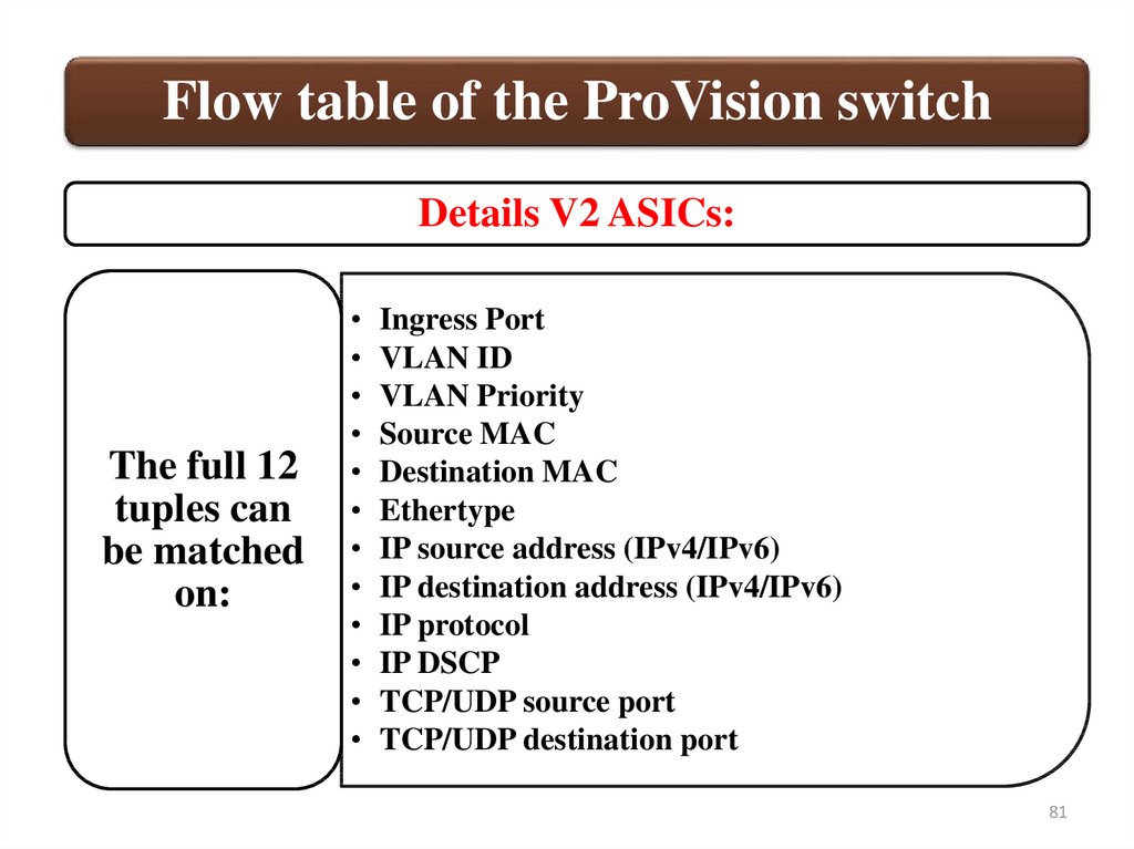
Flow table of the ProVision switchDetails V2 ASICs:
The full 12
tuples can
be matched
on:
Ingress Port
VLAN ID
VLAN Priority
Source MAC
Destination MAC
Ethertype
IP source address (IPv4/IPv6)
IP destination address (IPv4/IPv6)
IP protocol
IP DSCP
TCP/UDP source port
TCP/UDP destination port
81
82.
Flow table of the ProVision switchDetails V2 ASICs:
• Destination port (one or more
Not all 12
ports)
tuples can • Modify source MAC address
be actioned • Modify destination MAC
in
address
hardware • Modify VLAN ID
(six
• Modify VLAN priority
supported):
• Modify IP DSCP
82
83.
Flow table of the ProVision switchFigure shows V3 ASICs supported match and actions in hardware
(OpenFlow 1.3):
The OpenFlow tables can be
configured dynamically by SDN
Applications.
Result: A switch with V3 ASICs only, like the HP ProVision 5406R, can
match on all 12 tuple fields. Additional actions can also be supported.
83
84.
Flow table of the ProVision switchDetails V3 ASICs:
The full 12
tuples can
be matched
on:
Ingress Port
VLAN ID
VLAN Priority
Source MAC
Destination MAC
Ethertype
IP source address (IPv4/IPv6)
IP destination address (IPv4/IPv6)
IP protocol
IP DSCP
TCP/UDP source port
TCP/UDP destination port
84
85.
Flow table of the ProVision switchDetails V3 ASICs:
The
following
may be
actioned in
hardware:
Destination port (one or more ports)
Modify source MAC address
Modify destination MAC address
Modify VLAN ID
Modify VLAN priority
Modify IP DSCP
Modify IPv4 source address
Modify IPv4 destination address
Modify TCP/UDP source address (IPv4)
Modify TCP/UDP destination address (IPv4)
85
86.
Flow table of the ProVision switch38. We will now look at the table capability on our ProVision switch 1
(P1) — this will vary depending on the switch used: 3800 example
86
87.
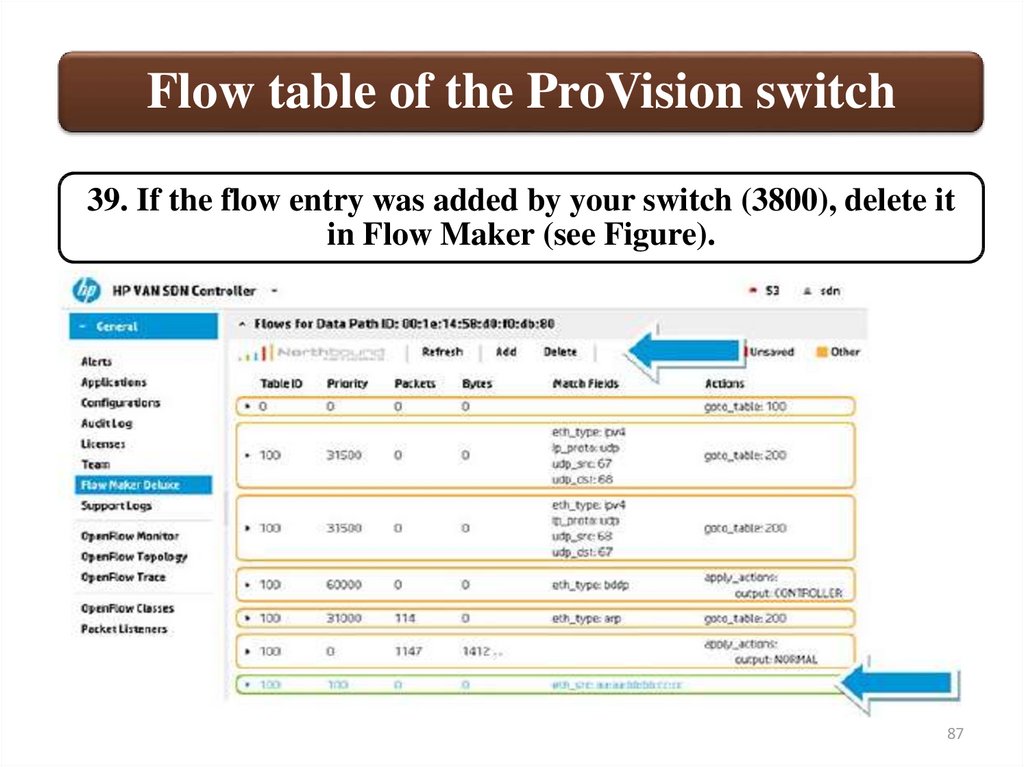
Flow table of the ProVision switch39. If the flow entry was added by your switch (3800), delete it
in Flow Maker (see Figure).
87
88.
Flow table of the ProVision switch40. In summary, the HP OpenFlow 1.3 Administrator Guide (see
Figure) shows the tables used by default on ProVision switches
that use V1 or V2 ASICs. Supported matches and actions are
ASIC dependent.
Tables in pipeline:
• Table 0: Read-only
• Table 100 (TCAM)
• Table 200 (Software)
88
89.
Flow table of the ProVision switchAn additional mode called IP Control table mode is also available on
ProVision switches. This extends the number of tables available in the
pipeline (see Figure).
89
90.
Flow table of the ProVision switch41. ProVision V3 ASIC switches such as the 5406R support more tables
and also support the dynamic creation of tables. By default tables 0, 1,
2, and 3 are available. But, in addition, rather than a switch informing a
controller of the tables available, the controller can tell the switch which
tables to create. An application requiring a specific pipeline can tell the
switch which tables to create, as illustrated in Figure.
90
91.
Flow table of the Comware switch42. What is the default table number used in Comware?
Answer: Comware uses a default table number of zero (OpenFlow
1.3). This is a hardware table.
43. Is this a hardware or a software table?
Answer: Comware switches use a hardware table. Comware
switches currently only support hardware tables.
44. Do Comware switches support hardware and software tables?
Answer: Comware switches currently only support hardware
tables.
45. If the switch only has a single OpenFlow table, will the switch
be complaint with the OpenFlow specification?
Answer: Yes, to be compliant with the OpenFlow specification, a
switch must support at least one table.
91
92.
Flow table of the Comware switchView the OpenFlow tables on Comware switch 2 (C2), as Figure
illustrates.
92
93.
Flow table of the Comware switch46. Open your saved Wireshark capture “Wireshark OpenFlow capture 1.pcapng.”
47. After a switch and a controller have sent Hello messages to each other, the
controller requests features from the switch. The switch replies with features and
this includes buffer support information, as illustrated in Figure.
93
94.
Flow table of the Comware switchTo see only buffer information of both switches, specify the following filter and
click Apply (see Figure and Figure): openflow_v4.switch_features.n_buffers.
ProVision
number of
buffers
94
95.
Flow table of the Comware switchComware
number of
buffers
n_buffers: The n_buffers field specifies the maximum number of packets
the switch can buffer when sending packets to the controller using
packet-in messages.
95
96.
Flow table of the Comware switch48. What is the value of the n_buffers field? Answer: On the
HP ProVision switch the n_buffers field is set to zero. On the
HP Comware switch the n_buffers field is set to 1024.
49. Do ProVision switches support packet buffering?
Answer: No, at the time of this writing, ProVision switches
using either V1 or V2 ASICs do not support packet
buffering (V1 or V2 ASICs, up to version 15.17 of software).
50. Do Comware switches support packet buffering?
Answer: Comware switches do support packet buffering.
51. If a switch buffers a packet, what is sent to the
controller?
Answers: Only header information is sent to the controller.
96
97.
Flow table of the Comware switch52. Clear the Wireshark filter and then start a
new Wireshark Capture, as illustrated in Figure.
97
98.
Flow table of the Comware switch53. In the Flow Maker application, add a match for the same source MAC
address, but in this case, write the entry to Table 200 of the ProVision switch.
Will this rule work?
Add a flow entry with
the following attributes
and then click Add, as
illustrated in Figure.
• Table ID: 200
• Priority: 100
• Src Mac: aaaabbbbcccc
• Instructions: Apply
Actions
• Action 1: No Action
• Save Flow = True
98
99.
Flow table of the Comware switch54. The flow entry is added to the flow table of the switch (both
3500 and 3800 switches) (see Figure).
Result: No error shows in Wireshark as the flow entry is accepted. Software
tables allow for matching and apply actions on the full 12 tuples.
99
100.
Flow table of the Comware switch55. Select the Comware switch (10.1.1.252) in Flow Maker
and add the following flow entry, as illustrated in Figure.
• Table ID: 0
• Priority: 100
• Src Mac:
bbbbccccdddd
• Instructions: Apply
Actions
• Action 1: No Action
• Save Flow = True
100
101.
Flow table of the Comware switch56. The flow entry is added to the flow table of the switch, as
illustrated in Figure.
Result: No error shows in Wireshark because the flow entry is accepted.
101
102.
Flow table of the Comware switch57. Stop the Wireshark capture (see Figure).
102
103.
InvestigatingOpenFlow
negotiations
5. Flow modifications
(Flow mod)
103
104.
Flow modifications (Flow mod)58. Change the filter in Wireshark, as illustrated in Figure.
• Set the Wireshark filter to: openflow_v4.flowmod.command.
• Click Apply.
104
105.
Flow modifications (Flow mod)59. What is a flow mod?
Answer: One of the controller-to-switch messages is Modify State:
Modify-State messages are sent by the controller to manage state on
the switches. Their primary purpose is to add, delete, and modify
flow and group entries in the OpenFlow tables and to set switch port
properties.
Flow modification messages can have the following types:
105
106.
Flow modifications (Flow mod)60. View the second message — the flow mod sent to Comware switch
10.1.1.252, shown in Figure. This message was sent from the
controller to the switch.
Result: This
is an
OFPFC_ADD
message.
The
controller is
adding a
new flow to
the switch.
106
107.
Flow modifications (Flow mod)61. View the result of the flow mod sent to ProVision switch
10.1.1.253, which is illustrated in Figure. This message is sent from
the controller to the switch.
Result:
This is
also an
OFPFC_
ADD
message
107
108.
Flow modifications (Flow mod)Note the packet number if you need to find it in the capture (see Figure).
62. Change the Wireshark filter to openflow_4 and click Apply, as
illustrated in Figure.
108
109.
Flow modifications (Flow mod)63. Find the barrier request message. This is after the flow mod and
called: OFPT_MULTIPART_REQUEST, OFPMP_FLOW (see Figure).
Controller-to-switch
messages are
initiated by the
controller and may
or may not require a
response from the
switch.
Barrier: Barrier
request/reply
messages are used
by the controller to
ensure message
dependencies have
been met or to
receive notifications
for completed
operations.
109
110.
Flow modifications (Flow mod)Message ordering: Ordering can be ensured through the use of barrier
messages. In the absence of barrier messages, switches may arbitrarily
reord messages to maximize performance. Hence, controllers should not
depend on a specific processing order. In particular, flow entries may be
inserted in tables in an order different from that of flow mod messages
received by the switch. Messages must not be reordered across a barrier
message and the barrier message must be processed only when all prior
messages have been processed.
More
precisely:
• 1. Messages before a barrier must be fully processed before the
barrier, including sending any resulting replies or errors.
• 2. The barrier must then be processed and a barrier reply sent.
• 3. Messages after the barrier may then begin processing.
If two messages from the controller depend on each other, they must be
separated by a barrier message. Examples of such message dependencies
include a group mod add with a flow mod add referencing the group, a port
mod with a packet-out forwarding to the port, or a flow mod add with a
following packet-out to OFPP_TABLE.
110
111.
Flow modifications (Flow mod)64. Find the barrier reply message (after the barrier request
— see Figure).
111
112.
Flow modifications (Flow mod)65. Does a switch notify the controller when an OpenFlow entry is
deleted?
Start the Wireshark capture (see Figure) and continue without
saving.
112
113.
Flow modifications (Flow mod)66. In Flow Maker, delete the flow entry you added from
the Comware switch (see Figure).
113
114.
Flow modifications (Flow mod)67. Delete the flow you added from the ProVision switch (see Figure).
114
115.
Flow modifications (Flow mod)68. Change the Wireshark filter to
openflow_v4.flow_removed.reason and click Apply (see Figure).
115
116.
Flow modifications (Flow mod)69. A message from the switch (10.1.1.252) was sent to the
controller, as illustrated in Figure.
In the Wireshark
capture, the
switch is
informing the
controller of the
flow removal
(OFPT_FLOW_RE
MOVED) and the
reason for the
removal
(OFPRR_DELETE
(2)).
116
117.
Flow modifications (Flow mod)“Flow entries are removed from flow tables in two ways, either at the request
of the controller or via the switch flow expiry mechanism.
“The switch flow expiry mechanism is run by the switch independently of the
controller and is based on the state and configuration of flow entries. Each
flow entry has an idle_timeout and a hard_timeout associated with it.
“The controller may actively remove flow entries from flow tables by sending
delete flow table modification messages (OFPFC_DELETE or
OFPFC_DELETE_STRICT).
“When a flow entry is removed, either by the controller or the flow expiry
mechanism, the switch must check the flow entry’s
OFPFF_SEND_FLOW_REM flag. If this flag is set, the switch must send a
flow removed message to the controller. Each flow removed message
contains a complete description of the flow entry, the reason for removal
(expiry or delete), the flow entry duration at the time of removal, and the
flow statistics at the time of removal.”
117
118.
Flow modifications (Flow mod)70. Change the Wireshark filter to openflow_v4 and click apply. A
flow mod message from the controller to the switch is seen
immediately before the flow removed message (see Figure).
118
119.
Flow modifications (Flow mod)Look at the flow_mod message. The application instructed the
controller to do a flow_mod using OFPFC_DELETE_STRICT (4),
as illustrated in Figure.
119
120.
Flow modifications (Flow mod)Flow table modification messages can have the following types:
120
121.
Flow modifications (Flow mod)For delete requests (OFPFC_DELETE or
OFPFC_DELETE_STRICT), if a matching entry exists in the
table, it must be deleted, and if the entry has the
OFPFF_SEND_FLOW_REM flag set, it should generate a flow
removed message. For delete requests, if no flow entry currently
residing in the requested table matches the request, no error is
recorded and no flow table modification occurs.
Codes:
• Type: OFPT_FLOW_MOD = 14
• Command: OFPFC_DELETE_STRICT = 4
In the Wireshark capture, a OFPT_FLOW_MOD (14) message
was sent by the controller to the switch and the command is set to
OFPFC_DELETE_STRICT (4). The switch therefore removes the
flow entry and informs the controller of the flow removal.
121
122.
Flow modifications (Flow mod)71. What happens when you try to send traffic from a valid
table to a nonexistent table in the OpenFlow pipeline
(goto_table instruction)?
Set the following in
Wireshark (see
Figure):
• Set the Wireshark filter to:
openflow_v4.error.type
• Click Apply
• Click Restart a new live capture
122
123.
Flow modifications (Flow mod)In Flow Maker, add a flow
entry with the following
attributes to the Provision
Switch (10.1.1.253)
and then click Add (see
Figure):
• Table ID: 100
• Priority: 100
• In Port: 2
• Instructions: Goto Table
• Table: 150
• Save Flow: True
123
124.
Flow modifications (Flow mod)The switch responds with a bad table message, as illustrated in Figure.
Result: If the instructions requested contain goto_table and the nexttable-id refers to an invalid table, the switch must return an
OFP_ERROR_MSG message with an OFPET_BAD_INSTRUCTION
type and a OFPBIC_BAD_TABLE_ID code.
124
125.
Flow modifications (Flow mod)72. What happens when you try to push a duplicate flow entry to the switch?
Add a flow entry to the
ProVision switch
(10.1.1.253) with the
following attributes and
then click Add (see
Figure):
• Table ID: 100
• Priority: 0
• Instructions: Apply
Actions
• Save Flow: True
125
126.
Flow modifications (Flow mod)Result: The switch responds with a OFPMFC_OVERLAP message, as
illustrated in Figure.
For add requests (OFPFC_ADD) with the OFPFF_CHECK_OVERLAP flag set,
the switch must first check for any overlapping flow entries in the requested
table. Two flow entries overlap if a single packet may match both, and both
entries have the same priority. If an overlap conflict exists between an existing
flow entry and the add request, the switch must refuse the addition and respond
with an ofp_error_msg message with the OFPET_FLOW_MOD_FAILED type
and OFPFMFC_OVERLAP code.
126
127.
Flow modifications (Flow mod)73. Where are flow statistics stored, on the controller or on a
switch?
Stop the Wireshark Capture (see Figure).
127
128.
Flow modifications (Flow mod)Set the
following in
Wireshark (see
Figures).
• Set the Wireshark filter to:
openflow_v4.flow_stats.priority
• Click Apply
• Click Start to start a new live capture
• Click Continue without Saving
128
129.
Flow modifications (Flow mod)In the Controller GUI, click OpenFlow Monitor, as illustrated in Figure.
Select the
Comware switch
(C2) and then click
Flows (see Figure).
129
130.
Flow modifications (Flow mod)View the message in the Wireshark capture (see Figure).
In this example,
both the
Wireshark capture
and the controller
interface show the
following: Packet
count: 1644.
This message was
sent from the
switch (10.1.1.252)
to the controller
(192.168.56.11).
130
131.
Flow modifications (Flow mod)Refresh the page on the controller (see Figure).
131
132.
Flow modifications (Flow mod)The
updated
packet
count is
shown in
the
Wireshark
capture
(1651
packets in
this
example)
(see
Figure).
132