


 english
 electronics
 warfare
Similar presentations:


Design of UAV systems
1.
Design of UAV SystemsLesson objective - to discuss
UAV Communications
including …
• RF Basics
• Communications Issues
• Sizing
Expectations - You will understand the basic
issues associated with UAV communications
and know how to define (size) a system to meet
overall communication requirements
c 2003 LM Corporation
Communications
9-1
2.
Design of UAV SystemsSchedule revision
Week 4
• Sortie rate estimates
• Requirements analysis
Week 5
• Communication considerations and sizing
Week 6
• Control station considerations and sizing
• Payload (EO/IR and radar) considerations and sizing
Week 7
• Reliability, maintenance, safety and support
• Life cycle cost
Week 8
• Mid term presentations
c 2003 LM Corporation
Communications
9-1a
3.
ImportanceDesign of UAV Systems
• Communications are a key element of the
overall UAV system
• A UAV system cannot operate without secure
and reliable communications
- unless it operates totally autonomously
- Only a few (generally older) UAVs operate
this way
• A good definition (and understanding) of
communications requirements is one of the
most important products of the UAV concept
design phase
c 2003 LM Corporation
Communications
9-2
4.
Design of UAV Systemsc 2003 LM Corporation
Discussion subjects
• RF basics
• Data link types
• Frequency bands
• Antennae
• Equations
• Communications issues
• Architecture
• Function
• Coverage
• Etc.
• Sizing (air and ground)
• Range
• Weight
• Volume
• Power
• Example problem
Communications
9-3
5.
Design of UAV SystemsData link types
• Simplex - One way point-to-point
• Half duplex - Two way, sequential Tx/Rx
• Full duplex - Two way, continuous Tx/Rx
• Modem - Device that sends data sent over analog link
• Omni directional - Theoretically a transmission in all
directions (4 steradian or antenna gain 0) but
generally means 360 degree azimuth coverage
• Directional - Transmitted energy focused in one
direction (receive antennae usually also directional)
- The more focused the antennae, the higher the gain
• Up links - used to control the UAV and sensors
• Down links - carry information from the UAV (location,
status, etc) and the onboard sensors
c 2003 LM Corporation
Communications
9-4
6.
Frequency bandsDesign of UAV Systems
Civil Radio band designation
1-10 kHz
VLF (very low frequency)
10-100 kHz
LF (low frequency)
100-1000 kHz
MF (medium frequency)
1-10 MHz
HF (high frequency)
10-100 MHz
VHF (very high frequency)
100-1000 MHz
UHF (ultra high frequency)
1-10 GHz
SHF (super high frequency)
10-100 GHz
EHF(extremely high frequency)
Note - NATO designations
US Military and Radar bands NATO
cover almost the same
1-2 GHz
L Band
D Band
2-4 GHz
S Band E/F Band
frequency ranges
4-8 GHz
C Band G/H Band
Satellite band designation
8-12 GHz
X Band I
Band
1700-3000 MHz
12-18 GHz
Ku Band J Band S Band
3700-4200 MHz
18-27 GHz
K Band K Band C Band
10.9-11.75 GHz
27-40 GHz
Ka Band K Band Ku1 Band
40-75 GHz
V Band L Band Ku2 Band
11.75-12.5 GHz
75-110 GHz
W Band M Band Ku3 Band
12.5-12.75 GHz
110-300 GHz
mm Band
Ka Band
18.0-20.0 GHz
300-3000 GHz
mm Band
c 2003 LM Corporation
Communications
9-5
7.
Design of UAV SystemsUAV frequencies
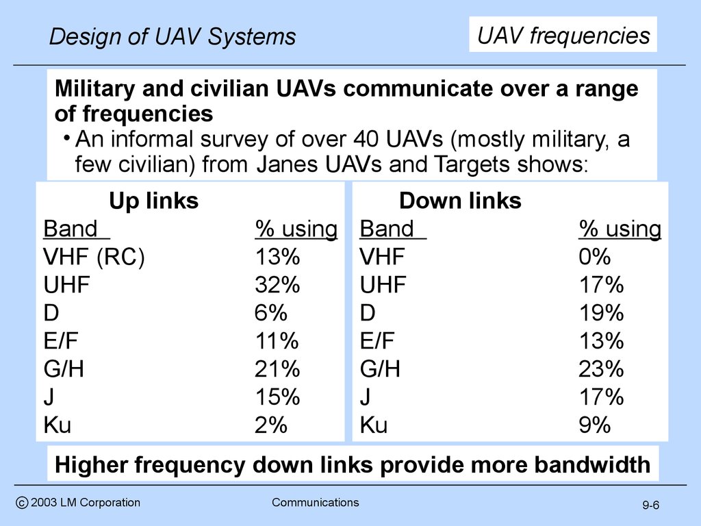
Military and civilian UAVs communicate over a range
of frequencies
• An informal survey of over 40 UAVs (mostly military, a
few civilian) from Janes UAVs and Targets shows:
Up links
Band
VHF (RC)
UHF
D
E/F
G/H
J
Ku
Down links
% using Band
13%
VHF
32%
UHF
6%
D
11%
E/F
21%
G/H
15%
J
2%
Ku
% using
0%
17%
19%
13%
23%
17%
9%
Higher frequency down links provide more bandwidth
c 2003 LM Corporation
Communications
9-6
8.
More basicsDesign of UAV Systems
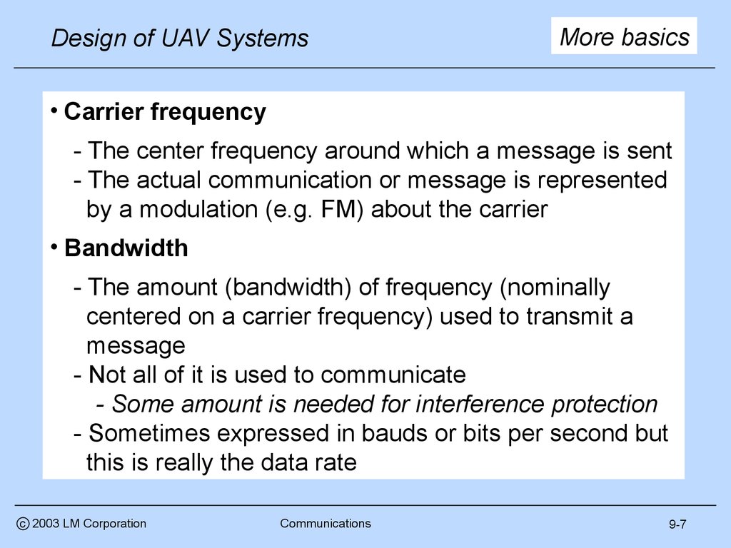
• Carrier frequency
- The center frequency around which a message is sent
- The actual communication or message is represented
by a modulation (e.g. FM) about the carrier
• Bandwidth
- The amount (bandwidth) of frequency (nominally
centered on a carrier frequency) used to transmit a
message
- Not all of it is used to communicate
- Some amount is needed for interference protection
- Sometimes expressed in bauds or bits per second but
this is really the data rate
c 2003 LM Corporation
Communications
9-7
9.
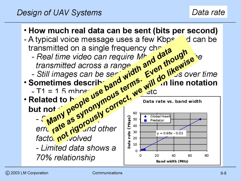
Data rateDesign of UAV Systems
• How much real data can be sent (bits per second)
- A typical voice message uses a few Kbps and can be
transmitted on a single frequency channel
ta gh
a
- Real time video can require Mbps and
d omust
u ebe
d
h wis
n
t
transmitted across a range of frequencies
a
n ke
h
e
t
v rates
li
- Still images can be sent at
data
over time
idlow E
o
w
.
• Sometimes describedausing
li l d line notation
nd rmstelecom
b 45 tmbps,
e ew
- T1 = 1.5 mbps; T3
=
etc
e
s
s
w
u
u o ct, Data rate vs. band width
• Related to bandwidth
e
l
p nym rre
o
o
e no
but not directly
c
p
60
y
y
y
Global Hawk
l
s
n
s
50
Predator
- Synchronization,
Ma e as orou
40
t
error rchecks
and
other
a rig
30
y = 0.69x - 0.03
t
20
o
factorsninvolved
10
- Limited data shows a
0
0
20
40
60
80
70% relationship
Band width (MHz)
c 2003 LM Corporation
Communications
9-8
10.
Design of UAV SystemsPolarity
• The physical orientation of an RF signal
- Typically determined by the design of the antenna
- But influenced by ground reflection
• Two types of polarization, linear and circular
- Linear polarity is further characterized as horizontal (“hpole”) or vertical (“v-pole”)
- A simple vertical antenna will transmit a vertically
polarized signal. The receiving antenna should also
be vertical
- V-pole tends to be absorbed by the earth and has
poor ground reflection ( tracking radars are V-pole).
- H-pole has good ground reflection which extends the
effective range ( used for acquisition radars)
- Circular polarity typically comes from a spiral antenna
- EHF SatCom transmissions are usually circular
- Polarization can be either right or left hand circular
c 2003 LM Corporation
Communications
9-9
11.
Design of UAV SystemsAnd more
• Antenna gain - a measure of antenna performance
- Typically defined in dBi = 10*log10(P/Pi)
- where P/Pi = ability of an antenna to focus power vs.
theoretical isotropic (4 steradian) radiation
- Example - an antenna that focuses 1 watt into a 3deg
x 3 deg beam (aka “beam width”) has a gain of
10*Log10(1/3^2/1/360^2) = 41.6 dB
- For many reasons (e.g., bit error rates) high gain
antennae (>20dBi) are required for high bandwidth data
Example - 10.5 Kbps Inmarsat Arero-H Antenna
- For small size and simplicity, low gain antenna (< 4 dBi)
are used………... for low bandwidth data
Example - 600 bps Inmarsat Aero-L Antenna
c 2003 LM Corporation
Communications
9-10
12.
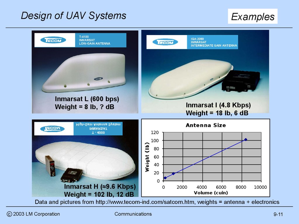
Design of UAV SystemsExamples
Inmarsat L (600 bps)
Weight = 8 lb, ? dB
Inmarsat I (4.8 Kbps)
Weight = 18 lb, 6 dB
Antenna Size
120
100
80
60
40
20
Inmarsat H (≈9.6 Kbps)
Weight = 102 lb, 12 dB
0
0
2000
4000
6000
Volume (cuin)
8000
10000
Data and pictures from http://www.tecom-ind.com/satcom.htm, weights = antenna + electronics
c 2003 LM Corporation
Communications
9-11
13.
Design of UAV SystemsMore basics - losses
Free space loss
- The loss in signal strength due to range (R)
= ( /4 R)^2
- Example : 10 GHz ( =0.03m) at 250 Km = 160.4 dBi
Atmospheric absorption
- Diatomic oxygen and water vapor absorb RF
emissions
- Example : 0.01 radian path angle at 250 Km = 2.6 dB
Precipitation absorption
- Rain and snow absorb RF emissions
- Example : 80 Km light rain cell at 250 Km = 6.5 dB
Examples from “Data Link Basics: The Link Budget”, L3 Communications
Systems West
c 2003 LM Corporation
Communications
9-12
14.
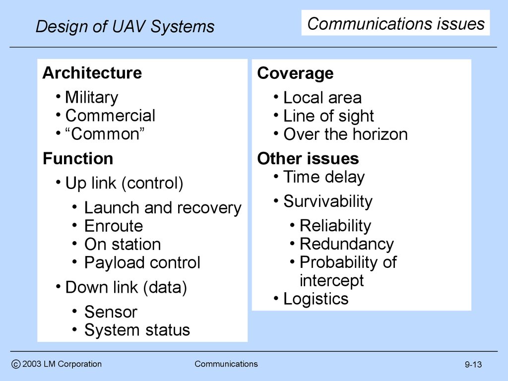
Design of UAV SystemsCommunications issues
Architecture
Coverage
• Military
• Local area
• Commercial
• Line of sight
• “Common”
• Over the horizon
Function
Other issues
• Time delay
• Up link (control)
• Survivability
• Launch and recovery
• Reliability
• Enroute
• Redundancy
• On station
• Probability of
• Payload control
intercept
• Down link (data)
• Logistics
• Sensor
• System status
c 2003 LM Corporation
Communications
9-13
15.
Design of UAV SystemsMilitary vs. civil
Military communications systems historically were
quite different from their civilian counterparts
• With the exception of fixed base (home country
infrastructure) installations, military communications
systems are designed for operations in remote
locations under extreme environmental conditions
• They are designed for transportability and modularity
- Most are palletized and come with environmental
shelters
Civilian communications systems were (and generally
still are) designed for operation from fixed bases
• Users are expected to provide an environmentally
controlled building (temperature and humidity)
Now, however, the situation has changed
c 2003 LM Corporation
Communications
9-14
16.
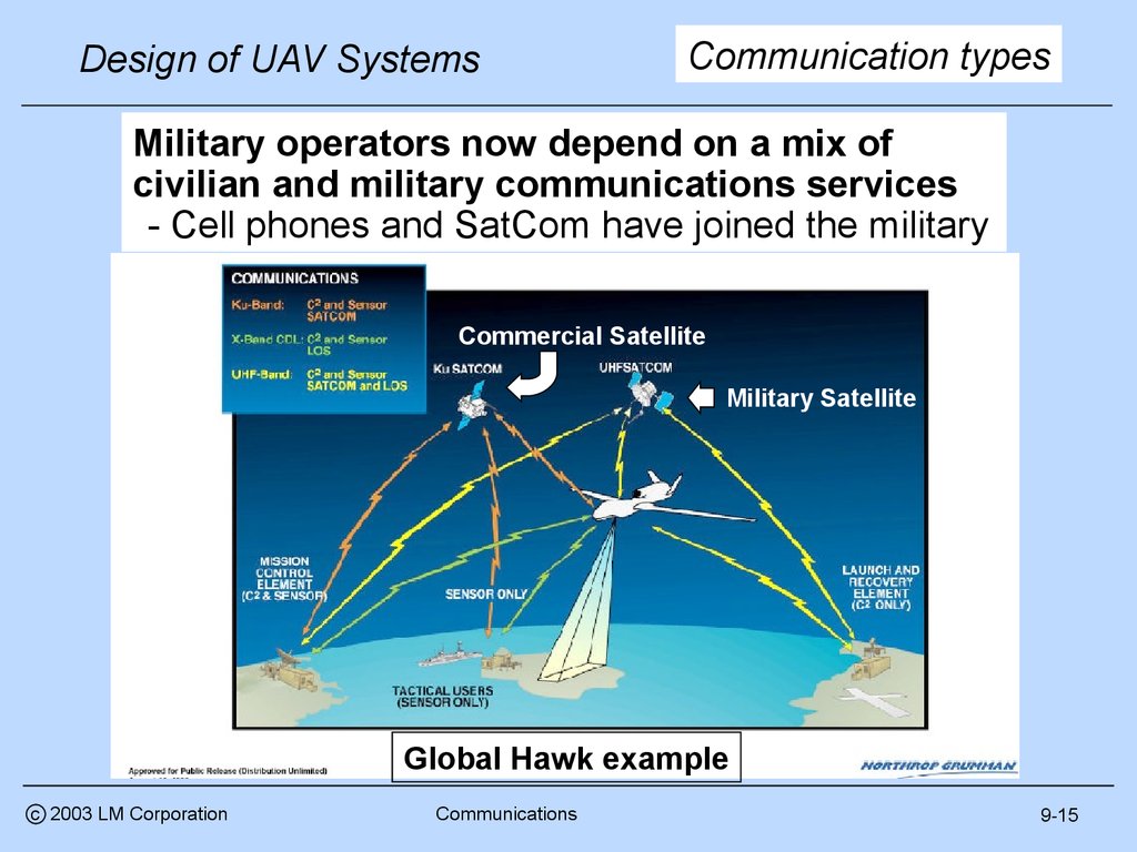
Design of UAV SystemsCommunication types
Military operators now depend on a mix of
civilian and military communications services
- Cell phones and SatCom have joined the military
Commercial Satellite
Military Satellite
Global Hawk example
c 2003 LM Corporation
Communications
9-15
17.
Design of UAV SystemsMilitary communications
Military communications systems generally fall into
one of two categories
• Integrated - multiple users, part of Dedicated
the communications infrastructure
• Dedicated - unique to a system
Requires no other
systems to operate
anywhere in the world
Integrated
http://www.fas.org/man/dod101/sys/smart/bgm109.htm
http://www.fas.org/man/dod101/sys/ac/equip/tbmcs.htm
c 2003 LM Corporation
Communications
9-16
18.
Design of UAV SystemsUAV architectures
UAV communication systems are generally dedicated
• The systems may have other applications (e.g. used by
manned and unmanned reconnaissance) but each UAV
generally has its own communications system
• US military UAVs have an objective of common data
link systems across all military UAVs (e.g.TCDL)
• Multiple UAV types could be controlled
• Frequencies or geographic areas are allocated to
specific UAVs to prevent interference or “fratricide”
UAV communications equipment is generally
integrated with the control station
• This is particularly true for small UAVs and control
stations
• Larger UAVs can have separate communications pallets
c 2003 LM Corporation
Communications
9-17
19.
Design of UAV SystemsUS common data links
- Survey of Current Air Force Tactical Data
Links and Policy, Mark Minges, Information Directorate, ARFL.
• Excerpts from
13 June 2001
• A program which defines a set of common and
interoperable waveform characteristics
• A full duplex, jam resistant, point-to-point digital,
wireless RF communication architecture
• Used with intelligence, surveillance and reconnaissance
(ISR) collection systems
• Classes & tech base examples
• Class IV (SatCom) - DCGS (Distributed Common Ground System)
• Class III (Multiple Access) - RIDEX (AFRL proposed)
• Class II (Protected) - ABIT (Airborne Information transfer)
• Class I (High Rate) - MIST (Meteorological info. std. terminal)
• Class I (Low Rate) - TCDL (Tactical CDL)
c 2003 LM Corporation
Communications
9-18
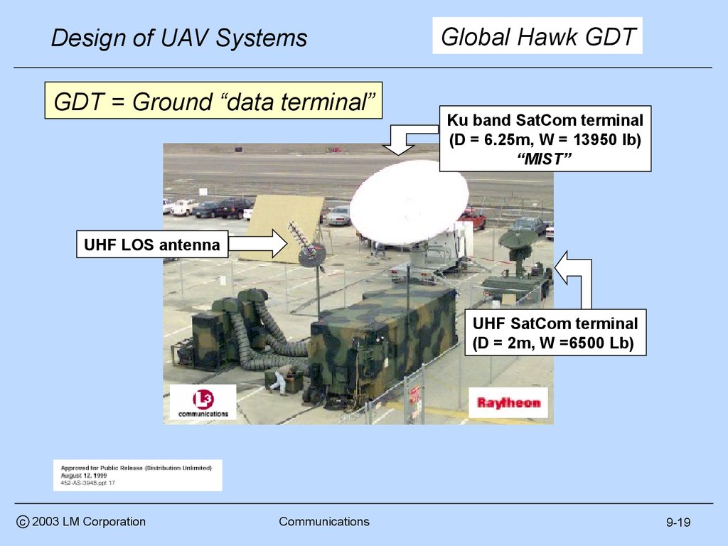
20.
Design of UAV SystemsGDT = Ground “data terminal”
Global Hawk GDT
Ku band SatCom terminal
(D = 6.25m, W = 13950 lb)
“MIST”
UHF LOS antenna
UHF SatCom terminal
(D = 2m, W =6500 Lb)
c 2003 LM Corporation
Communications
9-19
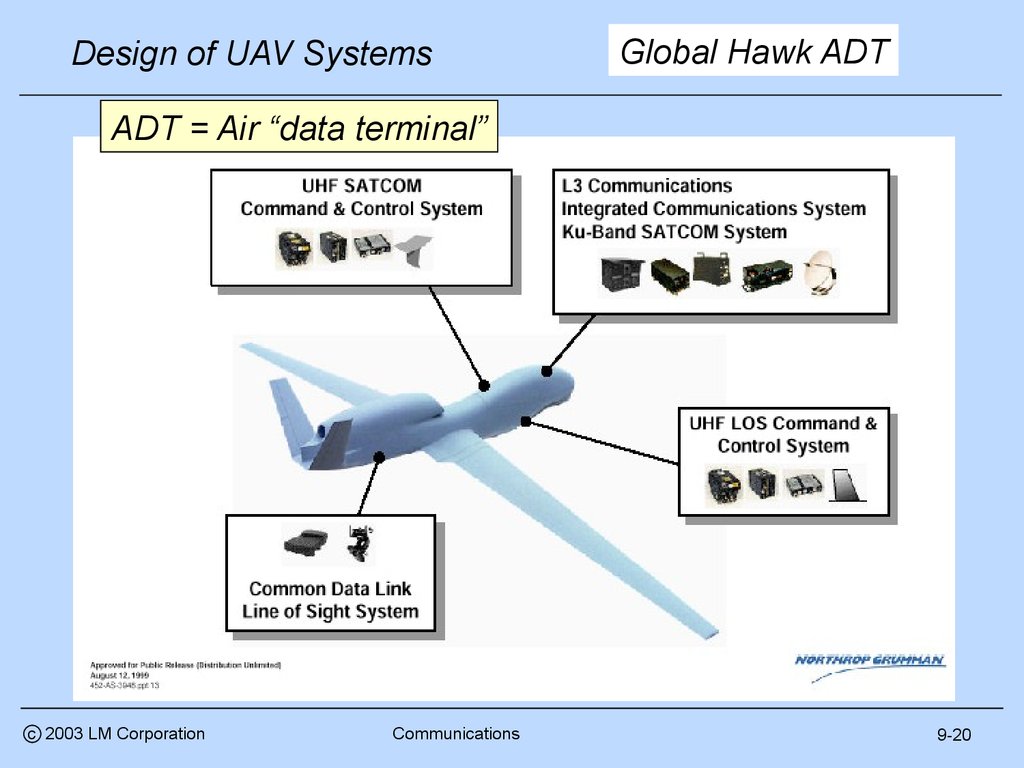
21.
Design of UAV SystemsGlobal Hawk ADT
ADT = Air “data terminal”
c 2003 LM Corporation
Communications
9-20
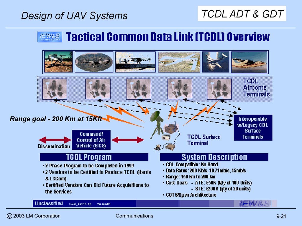
22.
TCDL ADT & GDTDesign of UAV Systems
Range goal - 200 Km at 15Kft
c 2003 LM Corporation
Communications
9-21
23.
Next subjectDesign of UAV Systems
Architecture
Coverage
• Military
• Local area
• Commercial
• Line of sight
• “Common”
• Over the horizon
Function
Other issues
• Time delay
• Up link (control)
• Survivability
• Launch and recovery
• Reliability
• Enroute
• Redundancy
• On station
• Probability of
• Payload control
intercept
• Down link (data)
• Logistics
• Sensor
• System status
c 2003 LM Corporation
Communications
9-22
24.
Control functionsDesign of UAV Systems
http://www.fas.org/irp/program/collect/pioneer.htm
http://www.fas.org/irp/program/collect/pioneer.htm
Launch and Recovery
Enroute
http://www.fas.org/irp/program/disseminate/uav_tcs.htm
On station
c 2003 LM Corporation
Payload
Communications
9-23
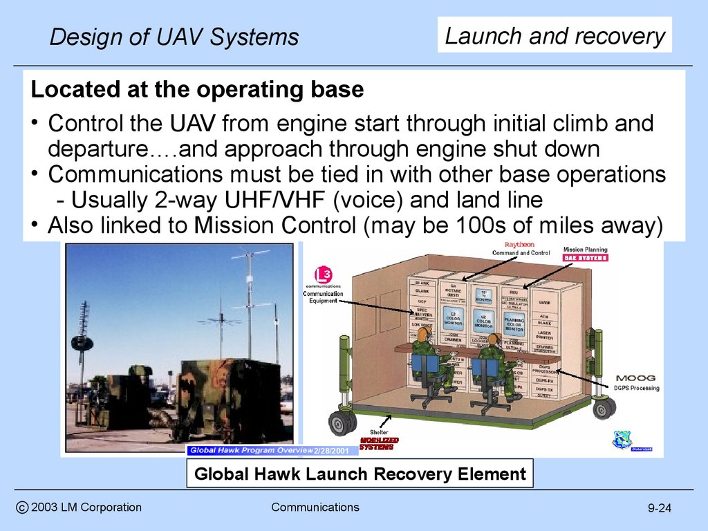
25.
Launch and recoveryDesign of UAV Systems
Located at the operating base
• Control the UAV from engine start through initial climb and
departure….and approach through engine shut down
• Communications must be tied in with other base operations
- Usually 2-way UHF/VHF (voice) and land line
• Also linked to Mission Control (may be 100s of miles away)
2/28/2001
Global Hawk Launch Recovery Element
c 2003 LM Corporation
Communications
9-24
26.
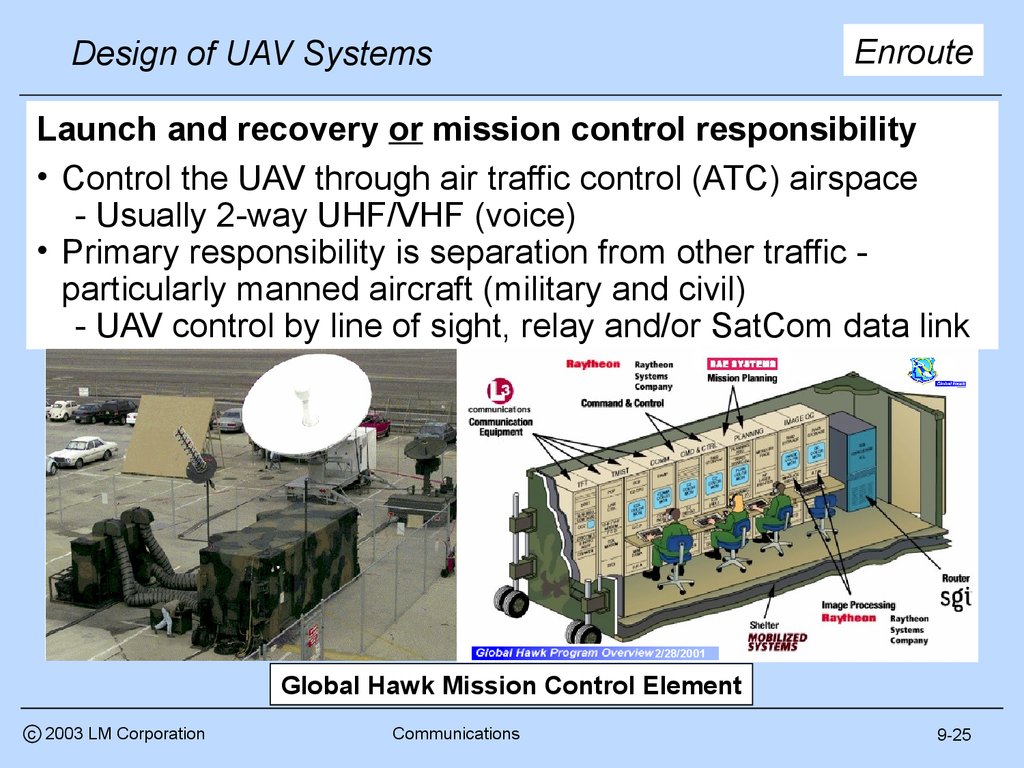
EnrouteDesign of UAV Systems
Launch and recovery or mission control responsibility
• Control the UAV through air traffic control (ATC) airspace
- Usually 2-way UHF/VHF (voice)
• Primary responsibility is separation from other traffic particularly manned aircraft (military and civil)
- UAV control by line of sight, relay and/or SatCom data link
2/28/2001
Global Hawk Mission Control Element
c 2003 LM Corporation
Communications
9-25
27.
Design of UAV SystemsOn station
Primary mission control responsibility
• Control the UAV air vehicle in the target area using line
of sight, relay and/or SatCom data link
- Bandwidth requirements typically 10s-100s Kpbs
• Control sometimes handed off to other users
- Mission control monitors the operation
http://www.fas.org/irp/program/collect/predator.htm
http://www.fas.org/irp/program/collect/predator.htm
c 2003 LM Corporation
Communications
9-26
28.
Design of UAV SystemsPayload
Primary mission control responsibility
• Control the sensors in the target area using line of sight,
relay and/or SatCom data links
- Sensor control modes include search and spot
- High bandwidth required (sensor control feedback)
• Sensor control sometimes handed off to other users
EO/IR sensor control
c 2003 LM Corporation
Communications
SAR radar control
9-27
29.
Design of UAV SystemsDown links
Down links carry the most valuable product of a UAV
mission
• UAV sensor and position information that is transmitted
back for analysis and dissemination
- Exception, autonomous UAV with on board storage
• Or UCAV targeting information that is transmitted back
for operator confirmation
Real time search mode requirements typically define
down link performance required
• Non-real time “Images” can be sent back over time and
reduce bandwidth requirements
Line of sight down link requirements cover a range
from a few Kbps to 100s of Mbps, SatCom down link
requirements are substantially lower
c 2003 LM Corporation
Communications
9-28
30.
Radar “imagery”Design of UAV Systems
High resolution “imagery” (whether real or synthetic)
establishes the down link bandwidth requirement
• Example - Global Hawk has 138,000 sqkm/day area
search area at 1m resolution. Assuming 8 bits per pixel
and 4:1 compression, the required data rate would be
3.2 Mbps to meet the SAR search requirements alone*
- In addition to this, the data link has to support 1900,
0.3 m resolution 2 Km x 2 Km SAP spot images per
day, an equivalent data rate of 2.0 Mbps
- Finally there is a ground moving target indicator
(GMTI) search rate of 15,000 sq. Km/min at 10 m
resolution, an implied data rate of about 5Mbps
• Total SAR data rate requirement is about 10 Mbps
*See the payload lesson for how these requirements are calculated
c 2003 LM Corporation
Communications
9-29
31.
EO/IR dataDesign of UAV Systems
EO/IR requirements are for comparable areas and
resolution. After compression, Global Hawk EO/IR
bandwidth requirements estimated at 42 Mbps*
EO spot image
2/28/2002
IR spot image
This is why Global Hawk has a high bandwidth data
link
* Flight International, 30 January 2002
c 2003 LM Corporation
Communications
9-30
32.
Design of UAV SystemsSystem status data
Air vehicle system status requirements are small
in comparison to sensors
- Fuel and electrical data can be reported with a few
bits of data at relatively low rates (as long as
nothing goes wrong - then higher rates required)
- Position, speed and attitude data files are also
small, albeit higher rate
- Subsystem (propulsion, electrical, flight control, etc)
and and avionics status reporting is probably the
stressing requirement, particularly in emergencies
Although important, system status bandwidth
requirements will not be design drivers
- A few Kbps should suffice
Once again, the sensors, not system status, will
drive the overall data link requirement
c 2003 LM Corporation
Communications
9-31
33.
Design of UAV SystemsNext subject
Architecture
Coverage
• Military
• Local area
• Commercial
• Line of sight
• “Common”
• Over the horizon
Function
Other issues
• Time delay
• Up link (control)
• Survivability
• Launch and recovery
• Reliability
• Enroute
• Redundancy
• On station
• Probability of
• Payload control
intercept
• Down link (data)
• Logistics
• Sensor
• System status
c 2003 LM Corporation
Communications
9-32
34.
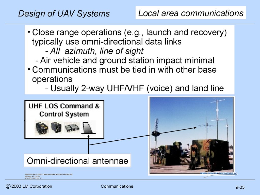
Design of UAV SystemsLocal area communications
• Close range operations (e.g., launch and recovery)
typically use omni-directional data links
- All azimuth, line of sight
- Air vehicle and ground station impact minimal
• Communications must be tied in with other base
operations
- Usually 2-way UHF/VHF (voice) and land line
Omni-directional antennae
c 2003 LM Corporation
Communications
9-33
35.
Long range comms (LOS)Design of UAV Systems
• Typically require directional data links
- RF focused on control station and/or air vehicle
- Impact on small air vehicles significant
- Impact on larger air vehicles less significant
- Significant control station impact
• Communications requirements include air traffic control
- Usually 2-way UHF/VHF (voice)
Global Hawk
Dipole
Pioneer
Steerable
Hunter
Dish
http://www.fas.org/irp/program/collect/pioneer.htm
http://www.fas.org/irp/program/collect/pioneer.htm
c 2003 LM Corporation
Communications
9-34
36.
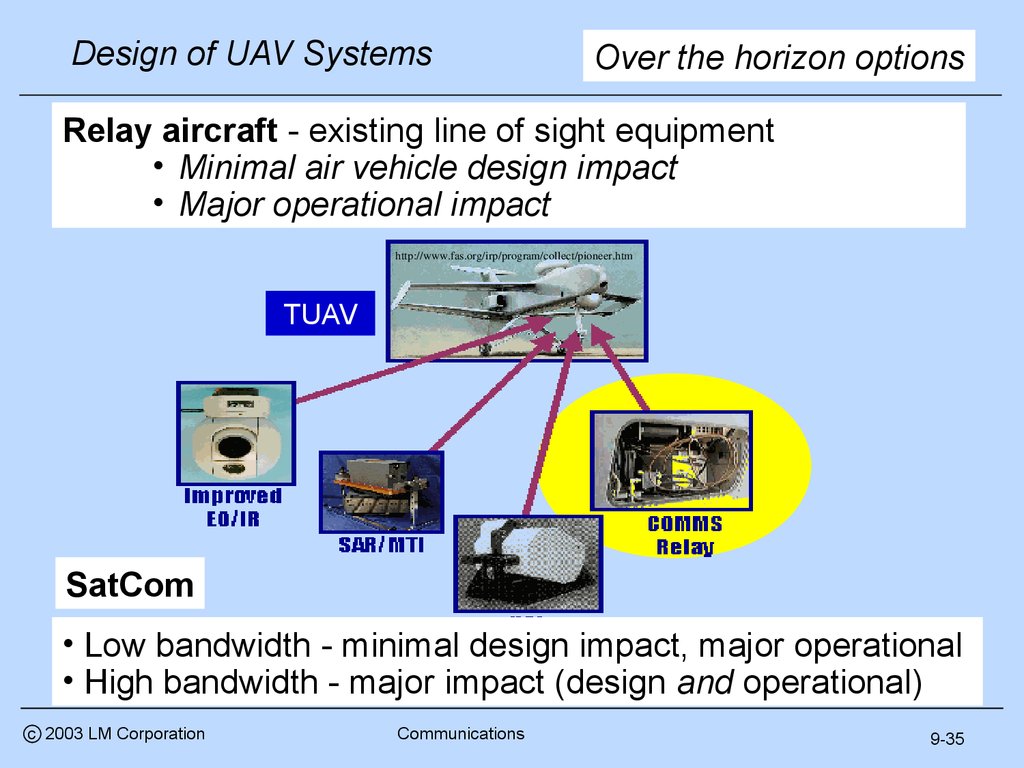
Design of UAV SystemsOver the horizon options
Relay aircraft - existing line of sight equipment
• Minimal air vehicle design impact
• Major operational impact
http://www.fas.org/irp/program/collect/pioneer.htm
TUAV
SatCom
• Low bandwidth - minimal design impact, major operational
• High bandwidth - major impact (design and operational)
c 2003 LM Corporation
Communications
9-35
37.
Design of UAV SystemsGlobal Hawk SatCom
Design issues
Ku-band antenna
Diameter = 1.22 m
Operational issues
Link availability
Bandwidth availability
Logistics
- Transportability
Operations and support cost
c 2003 LM Corporation
Communications
• Transmitter, receiver
- Size
- Weight
- Location
• Antennae
- Ditto
• Power and cooling
• Cost and complexity
D = 6.25m, W = 13950 lb
9-36
38.
Design of UAV SystemsArchitecture
Coverage
• Military
• Local area
• Commercial
• Line of sight
• UAV
• Over the horizon
Function
Other issues
• Time delay
• Up link (control)
• Survivability
• Launch and recovery
• Reliability
• Enroute
• Redundancy
• On station
• Probability of
• Payload control
intercept
• Down link (data)
• Logistics
• Sensor
• System status
c 2003 LM Corporation
Communications
9-37
39.
Design of UAV Systems• The time required to
transmit, execute and
feed back a command
(at the speed of light)
- A SatCom problem
• Example:
- 200 Km LOS @ c =
3x10^5 Km/sec
- Two way transmission
time = 1.33 msec
- Geo stationary Satcom
at 35,900 Km
- Two way transmission
time = 240 msec
c 2003 LM Corporation
Communications
Other issues - time delay
Two-way transmission time
1000
100
Inmarsat M
(500 msec?)
LOS
LEO
MEO
GEO
All
Power (All)
10
1
100
1000
10000
100000
One way distance (Km)
Raw data from, Automated Information
Systems Design Guidance Commercial Satellite Transmission, U.S.
Army Information Systems Engineering
Command
(http://www.fas.org/spp/military/docops/a
rmy/index.html)
9-38
40.
Design of UAV SystemsTime delays and UAVs
• Also known as data “latency” or “lag”
- Limited by speed of light and “clock speed”
• All systems have latency
- Human eye flicker detection - 30 Hz (33 msec delay)
- Computer screen refresh rate - 75 Hz (13 msec)
- Computer keyboard buffer latency - 10 to 20 msec
- LOS communications - 2 msec
- LEO SatCom - 10 msec
- MEO Satcom - 100 msec
- GEO Satcom - 200 to 300 msec
- Typical human reaction - 150-250 msec
• Acceptable overall system lag varies by task
< 40 msec for PIO susceptible flight tasks (low L/D)
< 100 msec for “up and away” flight tasks (high L/D)
• When OTH control latency > 40 msec, direct control
of a UAV is high risk (except through an autopilot)
c 2003 LM Corporation
Communications
9-39
41.
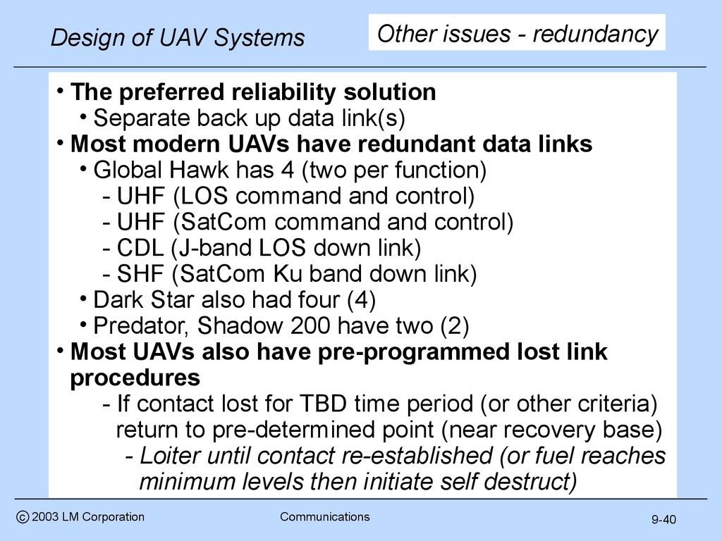
Design of UAV SystemsOther issues - redundancy
• The preferred reliability solution
• Separate back up data link(s)
• Most modern UAVs have redundant data links
• Global Hawk has 4 (two per function)
- UHF (LOS command and control)
- UHF (SatCom command and control)
- CDL (J-band LOS down link)
- SHF (SatCom Ku band down link)
• Dark Star also had four (4)
• Predator, Shadow 200 have two (2)
• Most UAVs also have pre-programmed lost link
procedures
- If contact lost for TBD time period (or other criteria)
return to pre-determined point (near recovery base)
- Loiter until contact re-established (or fuel reaches
minimum levels then initiate self destruct)
c 2003 LM Corporation
Communications
9-40
42.
Design of UAV SystemsProbability of intercept
• Probability that an adversary will be able to
detect and intercept a data link and be able to
1. Establish track on the UAV position
2. Interfere with (or spoof) commands
Wide beam
• Purely a military UAV issue
Max. power
• No known civil equivalent
• Some well known techniques
- Spread spectrum
- Random frequency hopping
- Burst transmissions
Narrow beam
- Difficult to detect and track
Min. power
- Power management
- No more power than required to receive
- Narrow beam widths
- Difficult intercept geometry
c 2003 LM Corporation
Communications
Adversary
9-41
43.
More issuesDesign of UAV Systems
• Power and cooling
• Communications equipment (especially transmitters)
require significant power and cooling to meet steady
state and peak requirements
- At low altitudes, meeting these power and cooling
requirements typically is not an issue
- At high altitude, both are a problem since power
and cooling required ≈ constant and ….
- Power available approximately proportional
- Cooling air required(cfm) approximately
proportional 1/ ; one reason why high-altitude
aircraft use fuel for cooling (also keeps the fuel
from freezing!)
c 2003 LM Corporation
Communications
9-42
44.
Design of UAV SystemsOther issues - logistics
A significant part of transport requirements are
associated with communications equipment
C-141B transport configuration
c 2003 LM Corporation
Communications
9-43
45.
Design of UAV Systemsc 2003 LM Corporation
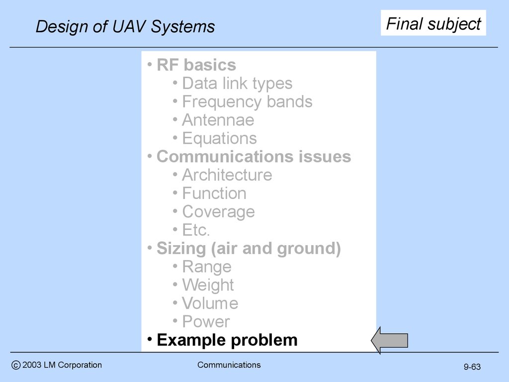
• RF basics
• Data link types
• Frequency bands
• Antennae
• Equations
• Communications issues
• Architecture
• Function
• Coverage
• Etc.
• Sizing (air and ground)
• Range
• Weight
• Volume
• Power
• Example problem
Communications
Next subject
9-44
46.
Design of UAV Systems Line of sight (LOS) calculations- Given 2 platforms at distance (D1+D2) apart at
altitudes h1 and h2 above the surface of the earth:
hmin
h1
D2
D1
h2
Re
- From geometry
D1+D2 Re*{ArcCos[(Re+hmin)/(Re+h2)]+
ArcCos[(Re+hmin)/(Re+h1)]} (9.1)
where
Re ≈ 6378 km (3444 nm)
hmin = intermediate terrain or weather avoidance altitude (≈ 20kft)*
and
ArcCos[ ] is measured in radians
*not applicable if h1 and/or h2 lower than hmin
c 2003 LM Corporation
Communications
9-45
47.
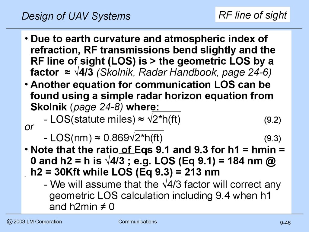
Design of UAV SystemsRF line of sight
• Due to earth curvature and atmospheric index of
refraction, RF transmissions bend slightly and the
RF line of sight (LOS) is > the geometric LOS by a
factor ≈ √4/3 (Skolnik, Radar Handbook, page 24-6)
• Another equation for communication LOS can be
found using a simple radar horizon equation from
Skolnik (page 24-8) where:
- LOS(statute miles) ≈ √2*h(ft)
(9.2)
or
- LOS(nm) ≈ 0.869√2*h(ft)
(9.3)
• Note that the ratio of Eqs 9.1 and 9.3 for h1 = hmin =
0 and h2 = h is √4/3 ; e.g. LOS (Eq 9.1) = 184 nm @
h2 = 30Kft while LOS (Eq 9.3) = 213 nm
- We will assume that the √4/3 factor will correct any
geometric LOS calculation including 9.4 when h1
and h2min ≠ 0
c 2003 LM Corporation
Communications
9-46
48.
Grazing angle effectsDesign of UAV Systems
• Given a platform at altitude h at grazing angle above
the horizon:
Local horizon
LO
S
h
• Ignore the small differences
between LOS and LOS’
• The equation predicts
published Global Hawk
comm ranges at 0.75
’
LOS
Re
• From geometry, the slant range (LOS’) will be given by:
or
(Re+h)^2 = LOS’^2 + Re^2 -2*LOS’*Re*Cos ( /2+ )
LOS’^2 - [2*Re*Cos ( /2+ )]*LOS’ + [Re^2 - (Re+h)^2] = 0 (9.4)
where LOS is the root of a quadratic equation of the form a*x^2+bx+c = 0
or x = [-b±sqrt(b^2-4*a*c)]/2*a
which we then multiply by √4/3 to adjust for atmospheric
effects
c 2003 LM Corporation
Communications
9-47
49.
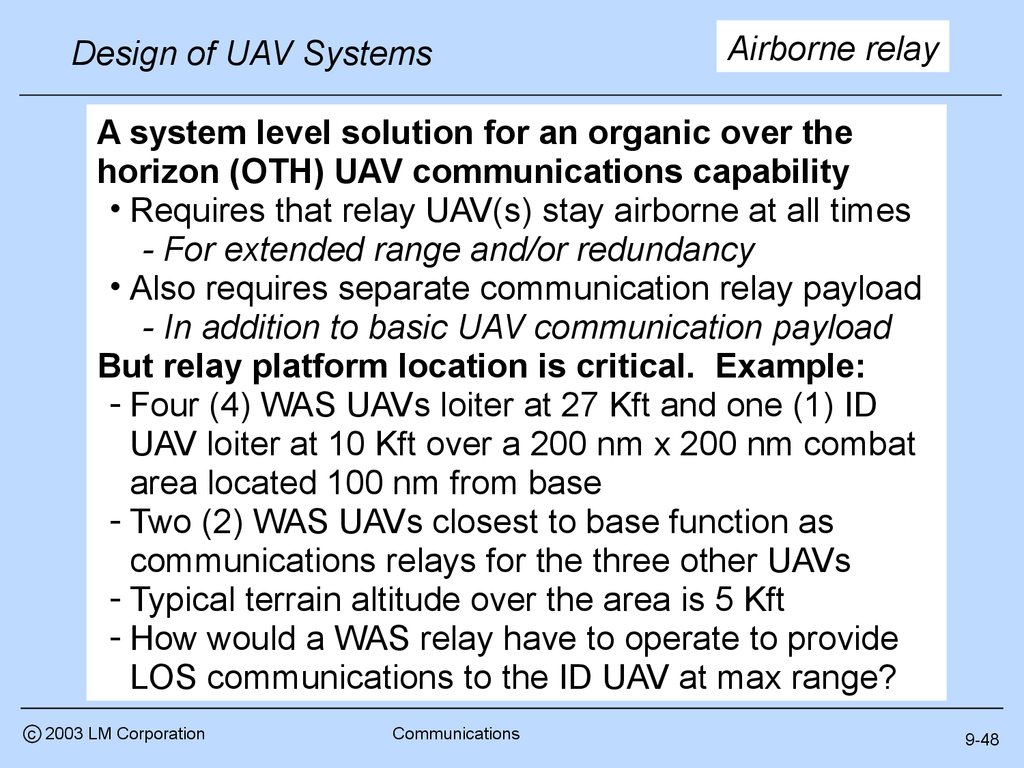
Design of UAV SystemsAirborne relay
A system level solution for an organic over the
horizon (OTH) UAV communications capability
• Requires that relay UAV(s) stay airborne at all times
- For extended range and/or redundancy
• Also requires separate communication relay payload
- In addition to basic UAV communication payload
But relay platform location is critical. Example:
- Four (4) WAS UAVs loiter at 27 Kft and one (1) ID
UAV loiter at 10 Kft over a 200 nm x 200 nm combat
area located 100 nm from base
- Two (2) WAS UAVs closest to base function as
communications relays for the three other UAVs
- Typical terrain altitude over the area is 5 Kft
- How would a WAS relay have to operate to provide
LOS communications to the ID UAV at max range?
c 2003 LM Corporation
Communications
9-48
50.
Relay exampleDesign of UAV Systems
• LOS defines max communication distance for relay
- At =0.75 , LOS from base = 156.7 nm vs. 158 nm req’d
- At hmin = 5 kft, LOS from ID UAV at 10 Kft to WAS relay
at 27 Kft = 269.2 nm vs. 212 nm req’d
• WAS altitude inadequate to meet base relay requirement
- Altitude increase to 27.4 Kft
200 nm x 200 nm
required
269.2 nm
156.7 nm
158 nm
212 nm
27 Kft
10 Kft
100 nm
c 2003 LM Corporation
Communications
9-49
51.
Design of UAV SystemsNext - sizing data
• There is little public information available on UAV
data links to use for initial sizing
- Including both air and ground data “terminals”
Short hand notation - ADT and GDT
• Three sources
1. Janes UAVs and Targets, Issue 14, June 2000
- Mostly military UAV data links
2. Unpublished notebook data on aircraft
communications equipment
- Both military and civil, not UAV unique
3. Wireless LAN data
- Collected from the internet, not aircraft qualified
- Indicative of what could be done with advanced
COTS technology
• For actual projects, use manufacturer supplied data
c 2003 LM Corporation
Communications
9-50
52.
ADT range and powerDesign of UAV Systems
LOS data links
200
Calculate LOS range
160
Equations 9.1-9.4
Estimate RF output
power required
120
80
40
0
0
100
200
300
Line of sight range (nm)
c 2003 LM Corporation
Communications
9-51
53.
Design of UAV SystemsInitial sizing - ADT Satcom
Bandwidth correlation
100000
Select Bandwidth
10000
1000
Select frequency
100
10
1
0
3
6
Global Hawk
Predator
Inmarsat
UHF
all
9 Expon.
12(all) 15
Frequency (GHz)
Parametric correlation basis
Parametric data source
All Satcom data links
Frequency range 0.24 - 15 GHz
Bandwidth range 0.6 Kbps - 5.0 Mbs
c 2003 LM Corporation
Communications
Known correlation between band
width or data rate and frequency
- Bandwidth availability increases
with frequency
9-52
54.
ADT power requiredDesign of UAV Systems
Power conversion
250
Line of sight
SatC om
Estimate input
power requirements
- LOS
- SatCom (GEO)
200
150
100
50
0
0
200
400
600
800
1000
Power consumption (W)
Parametric data source
Military line of sight data links
Frequency range 30 MHz - 15 GHz
Bandwidth range 0.01-5.0 Mbs
c 2003 LM Corporation
Communications
9-53
55.
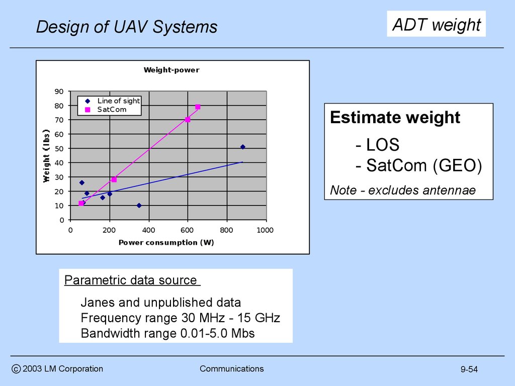
ADT weightDesign of UAV Systems
Weight-power
90
Line of sight
SatC om
80
Estimate weight
70
60
- LOS
- SatCom (GEO)
50
40
30
Note - excludes antennae
20
10
0
0
200
400
600
800
1000
Power consumption (W)
Parametric data source
Janes and unpublished data
Frequency range 30 MHz - 15 GHz
Bandwidth range 0.01-5.0 Mbs
c 2003 LM Corporation
Communications
9-54
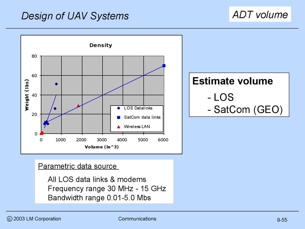
56.
ADT volumeDesign of UAV Systems
Density
80
60
Estimate volume
- LOS
- SatCom (GEO)
40
LOS Datalinks
20
SatCom data links
Wireless LAN
0
0
1000
Linear (SatCom
4000
5000
6000
data links)
Linear
(LOS
Volume (in^3)
Datalinks)
2000
3000
Parametric data source
All LOS data links & modems
Frequency range 30 MHz - 15 GHz
Bandwidth range 0.01-5.0 Mbs
c 2003 LM Corporation
Communications
9-55
57.
Design of UAV SystemsSatcom antenna size parametric
50
UHF
L band
Ku band
all
Log. (all)
40
30
ADT Satcom antenna
Estimate antenna “size”
Calculate area, volume or
length as appropriate
20
10
Parametric correlation basis
0
1
100
10000
1000000
Data rate (Kbps)
Known correlation between
bandwidth required and size
Antenna characteristic “size”
defined as following:
Parametric data source
All Satcom data link antenna
Frequency range 0.24 - 15 GHz
Bandwidth range 0.6 Kbps - 5.0 Mbs
c 2003 LM Corporation
Communications
- For EHF : square root of antenna
area (when known) or cube root
of installed volume
- For UHF : antenna length (blade)
or diameter (patch)
9-56
58.
Design of UAV SystemsADT satcom antenna
Satcom antenna weight
parametric
100
UHF
L band
Ku band
all
80
Estimate antenna
weight
60
40
20
0
5
10
15
20
25
30
Characteristic size (in)
Parametric data source
All Satcom data link antenna
Frequency range 0.24 - 15 GHz
Bandwidth range 0.6 Kbps - 5.0 Mbs
c 2003 LM Corporation
Communications
9-57
59.
More ADT LOS dataDesign of UAV Systems
Airborne weight & volume
Janes UAV data
links
Other military
data links
60
Janes UAV data links
0.035
Other military data links
50
0.030
C OTS wireless LAN
Median = .025
0.090
0.070
Median = .045
0.025
40
0.050
0.020
30
0.015
0.030
0.010
0.010
20
Wireless LAN
10
0.045
0.040
0
0
200
400
600
800
0.035
Volume (cuin)
0.030
0.025
Parametric data source
All LOS data links & modems
Frequency range 30 MHz - 15 GHz
Bandwidth range 0.01-5.0 Mbs
c 2003 LM Corporation
Median = .023
Communications
0.020
0.015
0.010
9-58
60.
Design of UAV SystemsInstallation considerations
• All systems on an air vehicle have an installation
weight and volume penalty (more in Lesson 19)
• We will assume a typical installation at 130% of dry
uninstalled weight
• We will make this assumption for all installed items
(mechanical systems, avionics, engines, etc.)
• Installed volume is estimated by allowing space
around periphery, assume 10% on each dimension
• Installed volume = 1.33 uninstalled volume
• For frequently removed items or those requiring air
cooling, we will add 25% to each dimension
• Installed volume = 1.95 uninstalled volume
• Payloads and data links should be installed this way
c 2003 LM Corporation
Communications
9-59
61.
Design of UAV SystemsGDT options
There are a few GDT system descriptions in Janes
and on the internet for UAV applications.
- Little technical data is provided but in general they are
large
- The CL-289 GDT is integrated into a truck mounted
ground control station and includes a 12 meter
hydraulic antenna mast
- The Elta EL/K-1861 has G and I-band dish antennae
(6 ft and 7ft diameter, respectively)
- The AAI GDT appears to be about a 2 meter cube
excluding the 1.83 m C-band antenna
- Smaller man portable systems are also described but
little technical performance data is included
The following parametrics are very approximate and
should be used only until you get better information
from manufacturers
c 2003 LM Corporation
Communications
9-60
62.
GDT parametricsDesign of UAV Systems
GDT weight vs. power
GDT weight vs. volume
1200
18000
1000
15000
12000
800
9000
600
6000
400
3000
200
0
0
50
100
150
200
250
0
300
0
Weight (lbs)
100
200
300
Weight (lb)
GDT Antenna Size
6
4
2
0
0
5
10
15
20
Frequency (GHz)
c 2003 LM Corporation
Communications
9-61
63.
ExpectationsDesign of UAV Systems
You should understand
• Communications fundamentals
• UAV unique communications issues
• How to calculate communication line of sight
• How to define (size) a system to meet overall
communication requirements
c 2003 LM Corporation
Communications
9-62
64.
Design of UAV Systemsc 2003 LM Corporation
• RF basics
• Data link types
• Frequency bands
• Antennae
• Equations
• Communications issues
• Architecture
• Function
• Coverage
• Etc.
• Sizing (air and ground)
• Range
• Weight
• Volume
• Power
• Example problem
Communications
Final subject
9-63
65.
Design of UAV SystemsExample problem
• Five medium UAVs, four provide wide area search, a
fifth provides positive target identification
Altitude
increase
- WAS range required (95km) not a challenge
required to
• Only one UAV responds to target ID requests meet LOS
relay
• No need to switch roles, simplifies ConOps
requirement
• No need for frequent climbs and descents
• Communications distances
27.4 Kft
reasonable (158nm & 212 nm)
• Speed requirement = 280 kts
• Air vehicle operating altitude
212 nm
differences reasonable
• We will study other
options as trades
27.4 Kft
158 nm 27.4 Kft 10 Kft
• What is a reasonable
communications
100 nm
architecture?
200 nm x 200 nm
• How big are the parts?
c 2003 LM Corporation
Communications
9-64
66.
Design of UAV SystemsADT sizing
• Parametric data is used to size (1) a basic UAV data
link and (2) a communications relay payload
• We assume both are identical and that all UAVs carry
both, allowing any UAV to function as a relay
• Provides communication system redundancy
• Parametric sizing as follows (for each system)
• Max range = 212 nm RF power = 110 W (Chart 51)
• Power consumption = 500 W (Chart 53)
• Weight = 27 lbm (Chart 54)
• Volume = 500 cuin (Chart 55)
• We have no non-Satcom antenna parametric data and
simply assume a 12 inch diameter dish, weighing 25
lbm with volume required = 2 cuft
• If you have no data, make an educated guess,
document it and move on
• We will always check the effect later
• We include communications in our payload definition
c 2003 LM Corporation
Communications
9-65
67.
GDT sizingDesign of UAV Systems
• We have little GDT parametric sizing date and
simply assume an ADT consistent input power
requirement (500W) and use the chart 60
parametrics to estimate weight and volume
• 250 lbm and 9.5 cuft
• Antenna size will be a function of frequency
and bandwidth which we will select after
assessing our payload down link requirements
c 2003 LM Corporation
Communications
9-66
68.
Design of UAV SystemsRequirements update
• System element
• GDT weight/volume/power excluding antenna (each)
= 205 lbm/9.5 cuft/500 W
• Air vehicle element
• GDT installations required = 2
• Cruise/loiter altitudes =
10 – 27.4Kft
• Payload element
• Installed weight/volume/power = TBD
• WAS
• Range/FOR /resolution/speed = 95 km/ 45 /10m/2mps
• Uninstalled weight/volume/power = TBD
• ID
• Type/range/resolution = TBD/TBD/0.5m
• Uninstalled weight/volume/power = TBD
• Communications
• Range/type = 212nm/air vehicle and payload C2I
• Uninstalled weight/volume/power 52 lbm/2.3 cuft/500 W
• Range/type = 158nm/communication relay
• Uninstalled weight/volume/power 52 lbm/2.3 cuft/500 W
c 2003 LM Corporation
Communications
9-67
69.
HomeworkDesign of UAV Systems
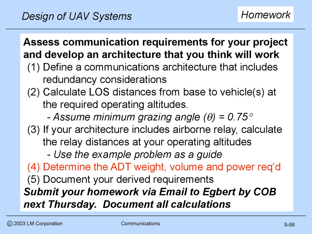
Assess communication requirements for your project
and develop an architecture that you think will work
(1) Define a communications architecture that includes
redundancy considerations
(2) Calculate LOS distances from base to vehicle(s) at
the required operating altitudes.
- Assume minimum grazing angle ( ) = 0.75
(3) If your architecture includes airborne relay, calculate
the relay distances at your operating altitudes
- Use the example problem as a guide
(4) Determine the ADT weight, volume and power req’d
(5) Document your derived requirements
Submit your homework via Email to Egbert by COB
next Thursday. Document all calculations
c 2003 LM Corporation
Communications
9-68
70.
Design of UAV Systemsc 2002 LM Corporation
Communications
Intermission
9-69